In summer 2020 I saw this DIY video and wanted to do something similar, but I had some reservations about the way that it has been done with an iMac chassis. Obviously, these types of displays look fantastic, but as a self-avowed Apple devotee, I just couldn’t stomach the idea of just having a 5k display in an Apple body that is even less functional than off-brand 5K displays that at least support downstream USB-c… it's like putting lipstick on a high-resolution pig. I have an Apple TB Display that I love and my dilemma was that I was either going to sacrifice design and buy something like the LG 5K display, or sacrifice at least some I/O ports in favour of an Apple chassis. The issue is that all of the DIY’s I’ve seen so far are using an LM270QQ1 panel in an iMac chassis and this display panel only fits in these chassis, and to do this the other internals are rendered useless.
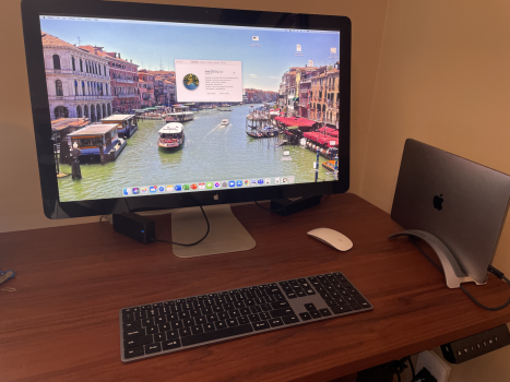
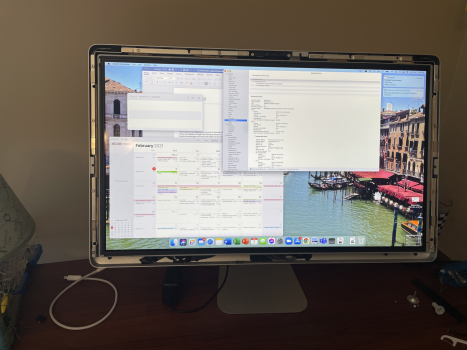
This post describes how I produced a solution that has the best of both worlds: I created a 5K display using an Apple thunderbolt display (TBD) chassis that preserves the I/O functionality, speaker/microphone, and the FaceTime camera of the TBD (which is still quite good compared to Apple's notebook cameras), adds a downstream USB-c connection and allows for charging and connectivity through one Thunderbolt 3/4 connection.
The idea of having a 5K Apple thunderbolt display has been around for a while, but so far I haven’t seen an example of it being done yet and Apple hasn’t made a consumer-oriented version yet (although it may yet come). I’ve previously considered trying to do it on my own, but just never thought it would be a valuable use of time and finances. But during COVID-19, I’ve had ample amounts of spare time and fewer social expenditures.
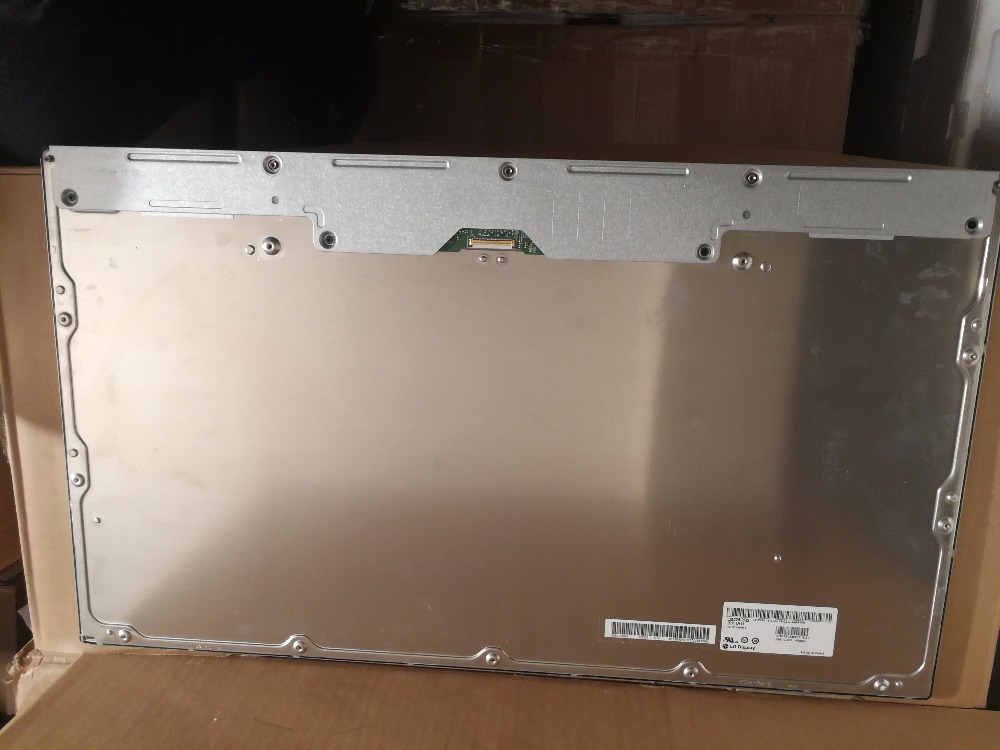
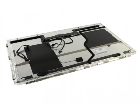
So I knew that the non-laminated 5K LM270QQ2 panel would be the best display choice as it is virtually identical to other panels that apple uses, except that it is in a traditional monitor frame, as opposed to the display being fully laminated to the glass in iMacs. I knew that the display size would be identical (27”) and should therefore at least fit well within the glass display cover that magnetically attaches to the TBD, but I was unsure exactly how/if the magnetic frame on the LM270QQ2 would work given the potential for thinner bezels on the 5K panel (spoiler alert, it didn’t fit as well as I had hoped).
One thing that I ran into which I foolishly hadn’t thought of was that the display thickness would be significantly different. While the standard display in the TBD is about 2cm thick, the LM270QQ2 is 7mm thick. This changed the way the display fit in the chassis and I had to get creative, but it had the added benefit of the internals I was adding were able to fit.
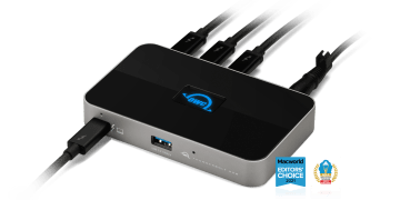
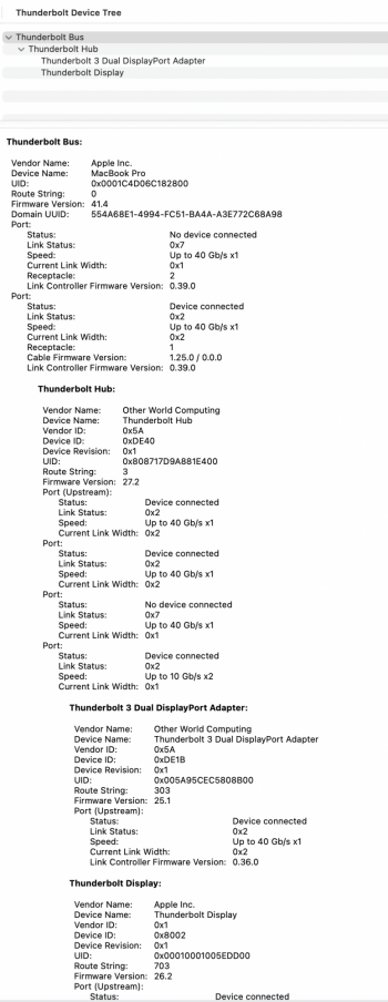
On the topic of the internals, I was not prepared for how tight it would be to get the internals that I would require into the chassis. It is worth noting at the point that this entire design is reliant on the new capabilities of Thunderbolt 4, which allows the branching of thunderbolt devices rather than just daisy-chaining. Aside from COVID-19 leaving me with more free time, I’ve been waiting for OWC’s new thunderbolt hub to be able to do this. It arrived this past week and I’ve spent 40+ hours since then completing this project.
It has three port which I've used to connect to
- the display panel (via an OWC dual DisplayPort to Thunderbolt 3 adapter)
- a USB-C extension cable to add a USB-C port, which also serves as an always-on 15 watt charging port
- the original TBD logic board (via an Apple TB2 to TB3 adapter)
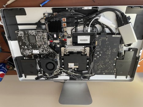
I wanted to house this, all of the TBD internals (to preserve I/O functionality), the 5K display control board, and the power supplies for everything, inside the TBD chassis. Unfortunately, I wasn’t able to accomplish all of this because of internal volume limitations. I had to leave the power supplies out in favour of ensuring the control board and the TB hub could fit. Perhaps the power supplies could be excluded altogether in the future if I’m able to figure out how to get the TBD’s native power supply to run both (which is very much possible consider there is a simple DC connection there from the MagSafe cable), but I don't think it’s in the cards given the complex circuitry in the TBD’s power supply (which unfortunately is still required to drive the I/O ports, and is going woefully under-utilized.
Perhaps one benefit of this is that I am really unconcerned about the additional heat that will be produced by the new internals because there is just less energy being converted/used by the internal components. This is good because I had to relocate the fan to a sub-optimal cooling position near the bottom of the display. That was just one of the really frustrating parts of this project… I had to cut/melt and remove lots of internal plastic that was hindering all of these components from fitting in and working properly.
The rest of this post will be a step-by-step guide on what I did/how I did it and I would appreciate any feedback you all have!
I started off by removing the glass panel using iFixit’s heavy-duty suction cups (right after disconnecting the display power). After that, I simply unscrewed the TR 10 screws around the frame, disconnected the display connections, and removed the display. Don’t throw it away, because it will be important to keep it around for size reference when trying to get your new display to fit inside the chassis properly. I then removed the magnetic attachments from the outside of the TBD’s display and set them aside. Be careful when you’re doing this: they are very malleable and are easily bent out of shape.
Next, I wanted to remove the built-in MagSafe 1/thunderbolt cable from the existing cable shielding. For a detailed guide on how to do the removal part of this, iFixit has you covered (https://www.ifixit.com/Guide/Apple+...hunderbolt+&+MagSafe+Cable+Replacement/112355). This was done carefully, because I needed to preserve the existing thunderbolt cable, due to the fairly unique profile that allows it to be easily connected to the TBD’s logic board. While you may be able to just do away with the cable harness entirely and not bother with the following steps, I didn’t want to have to go out and try and find a thunderbolt 1 or 2 cable that had a small enough connector to properly fit in TBD’s internal port (shown below). To remove the harness, you need to remove the cord from the TBD’s logic board, which entails unscrewing both the board and the connection cover mounted on the board. After that, the DC power cable powering the MagSafe cable can be disconnected (brown and black). Then, unscrew all screws holding in the centre speaker module and the EMC filter, which allows access to the metal plate holding the cables in relation to the display frame. The cable can then be pulled through and should be able to be fully removed from the display. Then there is the tricky part: separating the cables and getting them through the plastic cord organizer (which I wanted to preserve for using again). To do this I stripped the plastic coating around the MagSafe and the TB cord. I simply cut off the MagSafe cable as I have no reason to keep it. To get the braided TB cable through the plastic piece that neatly attaches to the display, I boiled some water until the plastic was soft enough to pull the small end of the TB cable through. I kept the plastic piece to use again as they are hard to replace.
After that, I removed the fan, a bunch of plastic, and liberated some wires so that the display control board, the Thunderbolt hub and the dual DisplayPort adapter had sufficient room. After a bit of plastic reshaping on the fan (with a grinder) I was able to fit it in below the power supply. The two cables running from it to the logic board weren't long enough so I (painstakingly) added a few inches to each wire which took a bit of soldering.
This step is optional, but I then added an opening for a USB C port. I just think this a no-brainer that somewhat future-proofs the display. Otherwise, you're stuck with USB A, and they're not even 3.0 or 3.1. I made the hole just to the left of the logic board with a drill and then used a metal file to square it up. The size will depend on the size of the female end you use. While you don't necessarily need the right-angled connector it just seems logical and will probably handle the wear and tear better.
Once all of that was finished I started working on the display. I basically built out the display panel with wood and hot glue so that the bezels would match the old display, which meant adding 3mm along the top, 4mm along each side, and 1.4cm to the bottom. I realized afterwards that popsicle sticks probably would've worked great for this, which would save using woodworking tools. After that was done, I checked that it fits into the chassis without touching the components on the inside. I then screwed back in the logic board and centre speaker, properly routed the wires, and did a final system check, power everything up and making sure it worked properly. There was a display connection issue the first time but after fixing that everything worked fine. I glued all the components in snugly, including the USB C extension cable and a right-angled adapter.
All that was then left was screwing back in the display and throwing on the external glass. I actually replaced mine because it had a couple of nicks in it.
Overall I'm very happy with the setup. It's worth noting that there are some ways to potentially get internals and ports working on an iMac with a 5K display as an external monitor for a MacBook, but at that point, why not just keep the iMac as a functional computer?
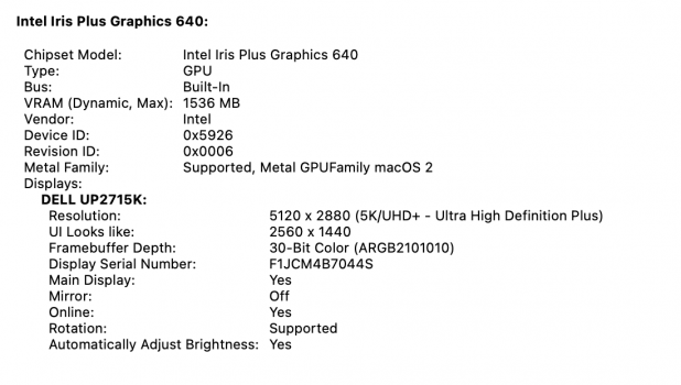
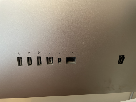
As would be expected, this display has functional ethernet, 3 USB 2.0 ports, a Thunderbolt 1 port, a Firewire 800 port, and a USB C 20 Gbps port. The original speakers sound as good as ever, and the FaceTime camera and microphone looks/sounds as nice or better than my 2017 MacBook Pro, which in case you were wondering, is what I'm driving this setup with. I believe a 2016 MacBook Pro could drive this as well, and maybe even a 2015 model if you went directly from the driver board to the MBP with two DP to MDP cables.
I'm using Apple's 2M Thunderbolt 3 cable, and since it is black I might even go the extra mile and paint the display space grey to match my MBP. I found a black power cable for an iMac Pro that will match for $15 if I go this route, and my Twelve South BackPack and book arc is space grey. If anyone has thoughts on what paint would be best to use for painting this chassis or any advice on whether or not to paint it, I'd appreciate all of your thoughts.
In case you're wondering, I did try to record it all on video but gave up partway through. I hope the pics suffice! Here is a list of all the components I purchased to pull this off. I already had the Thunderbolt Display, but you can get a used one in good condition for around $500 (all of these $ amounts are in Canadian dollars, not USD). You could probably buy everything you need for less than $1000 if you were smart about it, which compares nicely to Apple's 6K alternative, but maybe it's worth holding out for a future Apple 5K option. All I know is I'm feeling satisfied.
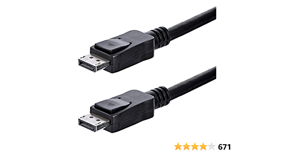
StarTech.com DisplayPort Cable - 1 ft x 2 - $22.99
OWC TB3 Dual Displayport Adapter $ 72.99
https://www.amazon.ca/dp/B077T485Y1/ref=cm_sw_r_cp_api_fabc_lyK4Fb3YESTHB?_encoding=UTF8&psc=1
27 inch 5K 5120*2880 IPS LCD screen module LM270QQ2 with controller - $631.54

 www.aliexpress.com
 www.aliexpress.com
$560 for OG thunderbolt display (used, approx.)
OWC Thunderbolt 4 Hub - $149 USD
 eshop.macsales.com
USB C extension cable $13.99
https://www.amazon.ca/gp/product/B074K318JK/ref=ppx_yo_dt_b_asin_title_o00_s00?ie=UTF8&psc=1
USB C right-angled connector $7.99
https://www.amazon.ca/gp/product/B077XCWJTG/ref=ppx_yo_dt_b_asin_title_o02_s00?ie=UTF8&psc=1
And tutorials that I found useful:
Replace TB Display glass panel
(OG DIY with an iMac chassis)

 forums.macrumors.com
Some other notes/background info
Some misc. tools and materials I used: soldering gun, solder, appropriate screwdrivers, some thin gauge wire, heat shrink wire wrappers/insulators, some wood, woodworking tools (I just use a table saw), a measuring tape, hot glue
The panel I bought only supports 5K over dual DisplayPort 1.2 but there is a new version that can apparently support Display 1.4 (which can do 5K in one cable) over USB C (or more likely thunderbolt 3, I would assume). I believe the disadvantage here is that it only supports 8-bit colour, which is probably good enough for most people
The display board comes with a remote control which you need for initial setup but isn't required afterwards. It’s useful to get to know the controls before attempted to change anything. My thanks go out to Cameron for figuring out that the buttons from left to right are:
The first button is the on/off button
Next is the LED, it’s useful for knowing the status of the display and also useful for navigating the next button when you cannot see what you’re pressing from behind the display
Red means the display is on standby
Yellow/green means the display is on and displaying a signal
No LED means it’s off
Next is the Menu button & Select Button
Next is Up
Next is Down
And the final button furthest to the right is exit/back & change input when not in the menus
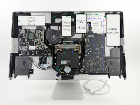
For what it is worth, here's the schematic that I drew up (green = DC and AC electrical wiring, red = DisplayPort, blue = thunderbolt/USB C)
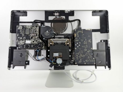
Due to the power supplies being larger than I expected and the Thunderbolt chassis having less room than I anticipated, it isn’t possible to fit the power supplied into the chassis (unless someone is able to find super a super slim power supply, but I wouldn't recommend deviating from the manufacturer's power supply) which isn’t a huge deal. The photos of the internal here are what I ended up with for size reference.
So far I haven't had any overheating issues with the monitor as a result of moving the fan (but I'll update this if I have any issues that could relate back to this).
This post describes how I produced a solution that has the best of both worlds: I created a 5K display using an Apple thunderbolt display (TBD) chassis that preserves the I/O functionality, speaker/microphone, and the FaceTime camera of the TBD (which is still quite good compared to Apple's notebook cameras), adds a downstream USB-c connection and allows for charging and connectivity through one Thunderbolt 3/4 connection.
The idea of having a 5K Apple thunderbolt display has been around for a while, but so far I haven’t seen an example of it being done yet and Apple hasn’t made a consumer-oriented version yet (although it may yet come). I’ve previously considered trying to do it on my own, but just never thought it would be a valuable use of time and finances. But during COVID-19, I’ve had ample amounts of spare time and fewer social expenditures.
So I knew that the non-laminated 5K LM270QQ2 panel would be the best display choice as it is virtually identical to other panels that apple uses, except that it is in a traditional monitor frame, as opposed to the display being fully laminated to the glass in iMacs. I knew that the display size would be identical (27”) and should therefore at least fit well within the glass display cover that magnetically attaches to the TBD, but I was unsure exactly how/if the magnetic frame on the LM270QQ2 would work given the potential for thinner bezels on the 5K panel (spoiler alert, it didn’t fit as well as I had hoped).
One thing that I ran into which I foolishly hadn’t thought of was that the display thickness would be significantly different. While the standard display in the TBD is about 2cm thick, the LM270QQ2 is 7mm thick. This changed the way the display fit in the chassis and I had to get creative, but it had the added benefit of the internals I was adding were able to fit.
On the topic of the internals, I was not prepared for how tight it would be to get the internals that I would require into the chassis. It is worth noting at the point that this entire design is reliant on the new capabilities of Thunderbolt 4, which allows the branching of thunderbolt devices rather than just daisy-chaining. Aside from COVID-19 leaving me with more free time, I’ve been waiting for OWC’s new thunderbolt hub to be able to do this. It arrived this past week and I’ve spent 40+ hours since then completing this project.
It has three port which I've used to connect to
- the display panel (via an OWC dual DisplayPort to Thunderbolt 3 adapter)
- a USB-C extension cable to add a USB-C port, which also serves as an always-on 15 watt charging port
- the original TBD logic board (via an Apple TB2 to TB3 adapter)
I wanted to house this, all of the TBD internals (to preserve I/O functionality), the 5K display control board, and the power supplies for everything, inside the TBD chassis. Unfortunately, I wasn’t able to accomplish all of this because of internal volume limitations. I had to leave the power supplies out in favour of ensuring the control board and the TB hub could fit. Perhaps the power supplies could be excluded altogether in the future if I’m able to figure out how to get the TBD’s native power supply to run both (which is very much possible consider there is a simple DC connection there from the MagSafe cable), but I don't think it’s in the cards given the complex circuitry in the TBD’s power supply (which unfortunately is still required to drive the I/O ports, and is going woefully under-utilized.
Perhaps one benefit of this is that I am really unconcerned about the additional heat that will be produced by the new internals because there is just less energy being converted/used by the internal components. This is good because I had to relocate the fan to a sub-optimal cooling position near the bottom of the display. That was just one of the really frustrating parts of this project… I had to cut/melt and remove lots of internal plastic that was hindering all of these components from fitting in and working properly.
The rest of this post will be a step-by-step guide on what I did/how I did it and I would appreciate any feedback you all have!
I started off by removing the glass panel using iFixit’s heavy-duty suction cups (right after disconnecting the display power). After that, I simply unscrewed the TR 10 screws around the frame, disconnected the display connections, and removed the display. Don’t throw it away, because it will be important to keep it around for size reference when trying to get your new display to fit inside the chassis properly. I then removed the magnetic attachments from the outside of the TBD’s display and set them aside. Be careful when you’re doing this: they are very malleable and are easily bent out of shape.
Next, I wanted to remove the built-in MagSafe 1/thunderbolt cable from the existing cable shielding. For a detailed guide on how to do the removal part of this, iFixit has you covered (https://www.ifixit.com/Guide/Apple+...hunderbolt+&+MagSafe+Cable+Replacement/112355). This was done carefully, because I needed to preserve the existing thunderbolt cable, due to the fairly unique profile that allows it to be easily connected to the TBD’s logic board. While you may be able to just do away with the cable harness entirely and not bother with the following steps, I didn’t want to have to go out and try and find a thunderbolt 1 or 2 cable that had a small enough connector to properly fit in TBD’s internal port (shown below). To remove the harness, you need to remove the cord from the TBD’s logic board, which entails unscrewing both the board and the connection cover mounted on the board. After that, the DC power cable powering the MagSafe cable can be disconnected (brown and black). Then, unscrew all screws holding in the centre speaker module and the EMC filter, which allows access to the metal plate holding the cables in relation to the display frame. The cable can then be pulled through and should be able to be fully removed from the display. Then there is the tricky part: separating the cables and getting them through the plastic cord organizer (which I wanted to preserve for using again). To do this I stripped the plastic coating around the MagSafe and the TB cord. I simply cut off the MagSafe cable as I have no reason to keep it. To get the braided TB cable through the plastic piece that neatly attaches to the display, I boiled some water until the plastic was soft enough to pull the small end of the TB cable through. I kept the plastic piece to use again as they are hard to replace.
After that, I removed the fan, a bunch of plastic, and liberated some wires so that the display control board, the Thunderbolt hub and the dual DisplayPort adapter had sufficient room. After a bit of plastic reshaping on the fan (with a grinder) I was able to fit it in below the power supply. The two cables running from it to the logic board weren't long enough so I (painstakingly) added a few inches to each wire which took a bit of soldering.
This step is optional, but I then added an opening for a USB C port. I just think this a no-brainer that somewhat future-proofs the display. Otherwise, you're stuck with USB A, and they're not even 3.0 or 3.1. I made the hole just to the left of the logic board with a drill and then used a metal file to square it up. The size will depend on the size of the female end you use. While you don't necessarily need the right-angled connector it just seems logical and will probably handle the wear and tear better.
Once all of that was finished I started working on the display. I basically built out the display panel with wood and hot glue so that the bezels would match the old display, which meant adding 3mm along the top, 4mm along each side, and 1.4cm to the bottom. I realized afterwards that popsicle sticks probably would've worked great for this, which would save using woodworking tools. After that was done, I checked that it fits into the chassis without touching the components on the inside. I then screwed back in the logic board and centre speaker, properly routed the wires, and did a final system check, power everything up and making sure it worked properly. There was a display connection issue the first time but after fixing that everything worked fine. I glued all the components in snugly, including the USB C extension cable and a right-angled adapter.
All that was then left was screwing back in the display and throwing on the external glass. I actually replaced mine because it had a couple of nicks in it.
Overall I'm very happy with the setup. It's worth noting that there are some ways to potentially get internals and ports working on an iMac with a 5K display as an external monitor for a MacBook, but at that point, why not just keep the iMac as a functional computer?
As would be expected, this display has functional ethernet, 3 USB 2.0 ports, a Thunderbolt 1 port, a Firewire 800 port, and a USB C 20 Gbps port. The original speakers sound as good as ever, and the FaceTime camera and microphone looks/sounds as nice or better than my 2017 MacBook Pro, which in case you were wondering, is what I'm driving this setup with. I believe a 2016 MacBook Pro could drive this as well, and maybe even a 2015 model if you went directly from the driver board to the MBP with two DP to MDP cables.
I'm using Apple's 2M Thunderbolt 3 cable, and since it is black I might even go the extra mile and paint the display space grey to match my MBP. I found a black power cable for an iMac Pro that will match for $15 if I go this route, and my Twelve South BackPack and book arc is space grey. If anyone has thoughts on what paint would be best to use for painting this chassis or any advice on whether or not to paint it, I'd appreciate all of your thoughts.
In case you're wondering, I did try to record it all on video but gave up partway through. I hope the pics suffice! Here is a list of all the components I purchased to pull this off. I already had the Thunderbolt Display, but you can get a used one in good condition for around $500 (all of these $ amounts are in Canadian dollars, not USD). You could probably buy everything you need for less than $1000 if you were smart about it, which compares nicely to Apple's 6K alternative, but maybe it's worth holding out for a future Apple 5K option. All I know is I'm feeling satisfied.
StarTech.com DisplayPort Cable - 1 ft x 2 - $22.99
StarTech.com DisplayPort Cable - 1 ft - with Latches - Short DP Cable - 4K DisplayPort to DisplayPort Cable - DisplayPort 2.1 Cable
The DISPLPORT1L 1ft DisplayPort 1.2 Cable with latches provides a secure, connection between your DisplayPort-equipped devices and is capable of providing higher performance than either HDMI or dual link DVI. The DP cable supports high resolutions of up to 4k x 2k (3840 x 2160) @ 60Hz with a maxi...
www.amazon.ca
OWC TB3 Dual Displayport Adapter $ 72.99
https://www.amazon.ca/dp/B077T485Y1/ref=cm_sw_r_cp_api_fabc_lyK4Fb3YESTHB?_encoding=UTF8&psc=1
27 inch 5K 5120*2880 IPS LCD screen module LM270QQ2 with controller - $631.54
Original New 27 inch 5K 5120*2880 IPS LCD screen module LM270QQ2 SP A3 Can match driver board For diy LG 27MD5KA display - AliExpress 7
Smarter Shopping, Better Living! Aliexpress.com
www.aliexpress.com
240.0US $ |Original Lcd Screen Lm270qq2 Spa1 Spa3 Lm270qq2-spa1 Sp A1 For Ultrafine 5k 27md5ka - Laptop Lcd Screen - AliExpress
Smarter Shopping, Better Living! Aliexpress.com
$560 for OG thunderbolt display (used, approx.)
OWC Thunderbolt 4 Hub - $149 USD
OWC Thunderbolt Hub: More Ports, More Power, More Creativity
Enhance your setup with 3 Thunderbolt 4 (USB-C) and 1 USB 3.2 port. Perfect for creatives needing seamless access to storage, displays, and accessories.
eshop.macsales.com
USB C extension cable $13.99
https://www.amazon.ca/gp/product/B074K318JK/ref=ppx_yo_dt_b_asin_title_o00_s00?ie=UTF8&psc=1
USB C right-angled connector $7.99
https://www.amazon.ca/gp/product/B077XCWJTG/ref=ppx_yo_dt_b_asin_title_o02_s00?ie=UTF8&psc=1
And tutorials that I found useful:
Replace TB Display glass panel
DIY 5k Monitor - success :-)
My "latest Macs" are a heavily upgraded 2009 Mac Pro (6c CPU, M.2 SSD, USB 3, RX580...) and more recently a 12c 2013 Mac Pro with an eGPU (Vega 56) - both machines with more than enough CPU power, GPU power and RAM for my needs, but I long aspired to upgrade to a nice 5k monitor to replace my...
forums.macrumors.com
Some other notes/background info
Some misc. tools and materials I used: soldering gun, solder, appropriate screwdrivers, some thin gauge wire, heat shrink wire wrappers/insulators, some wood, woodworking tools (I just use a table saw), a measuring tape, hot glue
The panel I bought only supports 5K over dual DisplayPort 1.2 but there is a new version that can apparently support Display 1.4 (which can do 5K in one cable) over USB C (or more likely thunderbolt 3, I would assume). I believe the disadvantage here is that it only supports 8-bit colour, which is probably good enough for most people
The display board comes with a remote control which you need for initial setup but isn't required afterwards. It’s useful to get to know the controls before attempted to change anything. My thanks go out to Cameron for figuring out that the buttons from left to right are:
The first button is the on/off button
Next is the LED, it’s useful for knowing the status of the display and also useful for navigating the next button when you cannot see what you’re pressing from behind the display
Red means the display is on standby
Yellow/green means the display is on and displaying a signal
No LED means it’s off
Next is the Menu button & Select Button
Next is Up
Next is Down
And the final button furthest to the right is exit/back & change input when not in the menus
For what it is worth, here's the schematic that I drew up (green = DC and AC electrical wiring, red = DisplayPort, blue = thunderbolt/USB C)
Due to the power supplies being larger than I expected and the Thunderbolt chassis having less room than I anticipated, it isn’t possible to fit the power supplied into the chassis (unless someone is able to find super a super slim power supply, but I wouldn't recommend deviating from the manufacturer's power supply) which isn’t a huge deal. The photos of the internal here are what I ended up with for size reference.
So far I haven't had any overheating issues with the monitor as a result of moving the fan (but I'll update this if I have any issues that could relate back to this).
Attachments
-
 tempImageMjKKf1.png3.5 MB · Views: 4,637
 -
 Screen Shot 2021-02-07 at 2.19.56 PM.png807.5 KB · Views: 2,228
 -
 IMG_0639 copy.jpg587.1 KB · Views: 2,594
 -
 tempImageTjck6c.png3 MB · Views: 2,363
 -
 Screen Shot 2021-02-07 at 2.13.20 PM.png102.8 KB · Views: 1,966
 -
 tempImageOgZsyB.png3.1 MB · Views: 1,993
 -
 OWC Hub-2.png407.8 KB · Views: 1,984
 -
 VQSb2fPo6WJUvMwQ.large.jpeg70.7 KB · Views: 1,834
 -
 ePSBDAfyxGSod6f5.large.jpeg37 KB · Views: 2,033
Last edited:
As an Amazon Associate, MacRumors earns a commission from qualifying purchases made through links in this post.
