Become a MacRumors Supporter for $50/year with no ads, ability to filter front page stories, and private forums.

cinerard

macrumors newbie
Original poster
Dec 30, 2019
25
25
I have an issue about the PCI Pool selector.

I have two Vega II DUO, so 4 BUS on them and 1 BUS with Mac I/O and 1 BUS at the top of the Mac. So 6 Thunderbolt BUS in total.

I have 3 RAID HDD tower (all of them are Thunderbolt 2) and a Blackmagic 4 k extreme (connected by Thunderbolt 2), + 2k monitor (connected in Display port with an Thunderbolt->Display Port adapter.)

If I connect my material as mentioned bellow. Pool B goes up to 150%... and POOL A stays at 0%, but I don't understand why.

- Vega II Duo Number 1 BUS 0 : RAID tower Number 1
- Vega II Duo Number 1 BUS 1 : RAID tower Number 2
- Vega II Duo Number 2 BUS 0 : RAID tower Number 3
- Vega II Duo Number 2 BUS 1 : Monitor 2k
- Mac I/O : Blackmagic 4k extrem

As I understand, everything should be right... but my POOL B exceed 100% and I can't force the Mac Pro to use POOL A... Do you know why ? Are Thunderbolt material automatically assigned to POOL B ?

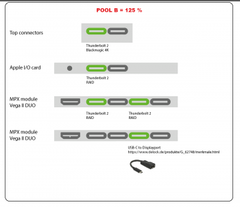
I made an other test. If I connect my material as mentioned bellow. Pool B don't exceed 100%... and POOL A stays at 0%.

- Vega II Duo Number 1 BUS 0 : monitor 2k
- Vega II Duo Number 2 BUS 0 : RAID tower Number 1
- Mac I/O : RAID tower Number 2
- Mac I/O : RAID tower Number 3
- Top Thunderbolt PORT : Blackmagic 4k extrem

For me it's not normal. And more strange, if I disconnect everything PCI indicator tells me that PCI cards aren't arranged in optimal configuration. (But this configuration comes from APPLE, two MPX and Mac I/O card).

Maybe, I'm wrong on something, but I don't know about what. I found a good article about this subject here : https://softron.zendesk.com/hc/en-u...OW-TO-Install-PCIe-cards-in-your-2019-Mac-Pro

Best

Robin
 
If you want to manually assign slots to a bandwidth pool, you would need to uncheck "Automatic Bandwidth Configuration" in the Expansion Slot Utility.

The Thunderbolt controller on the Apple I/O card is connected to PCIe lanes from slot 8. Each Vega II Duo MPX module contains two Thunderbolt controllers which are connected to PCIe lanes associated with slots 2 and 4 (the top slot in each MPX bay). So unless Apple forces Thunderbolt controllers on add-in cards into pool B, then you should be able to manually assign slots 2 and 4 to pool A and slot 8 to pool B. That should allow your original configuration to work without exceeding 100% on either pool. Or conversely, you could assign slot 8 to pool A and leave slots 2 and 4 on pool B.

Your second test configuration is almost certainly going to provide lower throughput regardless of the bandwidth pool allocation.

Your question is also somewhat related to the one I posted earlier about how the internal PCIe devices are connected (such as the Thunderbolt ports on the top of the case). Any chance you could run the following command in Terminal and share the output with me?

Code:
ioreg -xw80 -k IOPCIExpressLinkStatus | grep -e 'IOPCIDevice' -e 'IOPCIExpressLinkStatus'
 
Hello Robin,

I am working for Softron, a company developing software on the Mac, and we are the writer of the article you mentioned in your post. I am replying to your question here, and not on our help center where you also posted, as the question is not related to our software.

We don't have the same configuration as yours (we have a Vega II), but in our tests, we saw the same thing as you: all Thunderbolt allocations were made on Pool B. Even if we connected the Thunderbolt devices on the Vega II. For example, see the screenshot below, where we have one device connected to the Vega II (in slot 1):
Screenshot 2020-01-13 at 16.36.25.png

As you can see the graphics card itself can not be allocated to a slot (maybe it's different with the Duo, can you share a screenshot of your Expansion Slot Utility?). Slots 3 and 1 are using a "reserved" PCIe bandwidth, out of the allocation, they have their own dedicated bandwidth, which makes sense so you are sure that whatever you do with your pool allocations, slots 1 and 3 (where the graphics cards usually are) are "safe".

The fact that your second configuration uses less bandwidth is most probably related to the fact that you are using less Thunderbolt BUS. In your first configuration, if I read correctly, you are using 5 different BUS, whereas, in your second, you are using 3 different BUS. As:
  • each Pool has 16 lanes of PCIe3
  • each Thunderbolt BUS where a device is connected will allocate 4 lanes
  • all Thunderbolt BUS are allocated to pool B
  • the Mac Io card in slot 8 already uses 4 lanes of pool B
Then if you do the math your results are only "logical". (I'll let you do the math)

If you are interested, we have another article that explains where we could see the different BUS were located on the Mac Pro: https://softron.zendesk.com/hc/en-u...ect-Thunderbolt-devices-for-best-performances

Now the question is: do you have any issue with any of these configuration (first or second). Because, while "each Thunderbolt BUS where a device is connected will allocate 4 lanes" it doesn't mean it will use all 4 lanes. For example:
  • the Mac I/o card already allocates 4 lanes. If you just connect one Thunderbolt device to it and nothing else, the expansion slot utility will "allocate" 8 lanes in total, but in fact will only use 4 lanes.
  • your Monitor "allocates" PCIe lanes as it probably has a Thunderbolt port, but if it's only used as a monitor, I think it will use the DisplayPort (not sure of the model of your Monitor, so I'm shooting in the dark), so it won't use the PCIe lanes
  • you will probably not read at full speed from your 3 storage
  • etc...
So there are many things to consider, and the expansion slot utility is a great tool to check your configuration, but it can not know in advance what you'll do with your configuration. It only tells you that if you use all bandwidth of all devices (TB and PCIe) simultaneously, you may have issue on some of them...

I hope this helps and that it all makes sense.

Pierre
 
Hello Robin,

I am working for Softron, a company developing software on the Mac, and we are the writer of the article you mentioned in your post. I am replying to your question here, and not on our help center where you also posted, as the question is not related to our software.

We don't have the same configuration as yours (we have a Vega II), but in our tests, we saw the same thing as you: all Thunderbolt allocations were made on Pool B. Even if we connected the Thunderbolt devices on the Vega II. For example, see the screenshot below, where we have one device connected to the Vega II (in slot 1):
View attachment 888327
As you can see the graphics card itself can not be allocated to a slot (maybe it's different with the Duo, can you share a screenshot of your Expansion Slot Utility?). Slots 3 and 1 are using a "reserved" PCIe bandwidth, out of the allocation, they have their own dedicated bandwidth, which makes sense so you are sure that whatever you do with your pool allocations, slots 1 and 3 (where the graphics cards usually are) are "safe".

The fact that your second configuration uses less bandwidth is most probably related to the fact that you are using less Thunderbolt BUS. In your first configuration, if I read correctly, you are using 5 different BUS, whereas, in your second, you are using 3 different BUS. As:
  • each Pool has 16 lanes of PCIe3
  • each Thunderbolt BUS where a device is connected will allocate 4 lanes
  • all Thunderbolt BUS are allocated to pool B
  • the Mac Io card in slot 8 already uses 4 lanes of pool B
Then if you do the math your results are only "logical". (I'll let you do the math)

If you are interested, we have another article that explains where we could see the different BUS were located on the Mac Pro: https://softron.zendesk.com/hc/en-u...ect-Thunderbolt-devices-for-best-performances

Now the question is: do you have any issue with any of these configuration (first or second). Because, while "each Thunderbolt BUS where a device is connected will allocate 4 lanes" it doesn't mean it will use all 4 lanes. For example:
  • the Mac I/o card already allocates 4 lanes. If you just connect one Thunderbolt device to it and nothing else, the expansion slot utility will "allocate" 8 lanes in total, but in fact will only use 4 lanes.
  • your Monitor "allocates" PCIe lanes as it probably has a Thunderbolt port, but if it's only used as a monitor, I think it will use the DisplayPort (not sure of the model of your Monitor, so I'm shooting in the dark), so it won't use the PCIe lanes
  • you will probably not read at full speed from your 3 storage
  • etc...
So there are many things to consider, and the expansion slot utility is a great tool to check your configuration, but it can not know in advance what you'll do with your configuration. It only tells you that if you use all bandwidth of all devices (TB and PCIe) simultaneously, you may have issue on some of them...

I hope this helps and that it all makes sense.

Pierre

Dear Pierre, Cher Pierre,

Merci pour votre message très précis et très clair. I continue in English ;-)

I wrote a post on Softron because you are the only source of information I found about this. Your article is very well done. And Thank's to answer this question here, on MacRumors.

You explained very well what is happening (much better than in the Apple online manual), and you are right ; According to "math", it's normal than I exceed Pool B with my thunderbolt connexion. In an other hand, I don't understand why it's impossible to use Pool A to connect thunderbolt... Because, it's a little bit useless to have 12 Thunderbolt ports if it's impossible to use POOL A to optimized their bandwidth.

Find bellow two capture screen of my system. You will notice it's impossible to change in manual anything on PCI utilities. PCI N°8 stays with POOL B, even in manual mode.

An other strange thing is this x0 on PCI N°2. I noticed, it's the same on your system. Maybe the warning message "Les cartes PCI installées..." are connected with that. Do you have the same message on your system ?

For now, I didn't noticed any performance problem with both of these configuration. But I should do more test to be sure.

Capture d’écran 2020-01-13 à 12.48.29.png
Capture d’écran 2020-01-13 à 12.59.53.png
 
I have an issue about the PCI Pool selector.

I have two Vega II DUO, so 4 BUS on them and 1 BUS with Mac I/O and 1 BUS at the top of the Mac. So 6 Thunderbolt BUS in total.

....

Maybe, I'm wrong on something, but I don't know about what. I found a good article about this subject here : https://softron.zendesk.com/hc/en-u...OW-TO-Install-PCIe-cards-in-your-2019-Mac-Pro
...

If the article is right then there is no control over which pool the Thunderbolt device hook to.

".. Thunderbolt devices will only be allocated to Pool B. So if you the manual configuration, make sure to leave some free bandwidth on Pool B. ..."

Pragmatically it looks as those Slot 4 , Slot 2 , and the Thunderbolt devices are all feed from the Pool B x16 source. Nominally, Slot 5 is fed from the other last x16 (if used), but can swap to the loaded down Pool B if manually want to juggle. ( Apple somewhat tags slot 5 as the Afterburner slot . Especially with two DUO, as that is the only option left. And their three Afterburner set up must basically avoid any PCI-e TB workload any another other slot besides a single GPU. ) .

Even in manual allocation mode the expansion slot utility doesn't allow for adjustments to slots 2 and 4. Thunderbolt is just in the same 'boat'. If you have the two DUO setup, then the four Thunderbolt controllers ( one on each card , top , and rear ) split up the x16 Pool B feed completely. That would mean would need to get other cards in slots 5-8 onto pool A to stay completely out of their way.

That said, if some of the stuff is TBv2 sitting on a TBv3 bus then pragmatically it may not be as overloaded at the indicator portrays. Those devices are only using half the possible bandwidth. ( I suspect the indictor is talking about bandwidth allocation at the PCI-e v3 level (how many lanes active) and perhaps not nit picking about actual, dynamic throughput. ). Similar with PCI-e v2 cards. The throughput isn't what v3 card would be, but the lanes are "lit up" the same way as being active.


x16 ---> Slot 1
x16 ----> Slot 3
x16 ----> Pool A
x16 ----> Pool B

Pool B slot 2 , 3 , and thunderbolts controllers ( MPX connectors and top , bottom) [ optionally 5,6,7,8]
Pool A [optionally 5,6,7, 8 ]

The USB controllers on the I/O card probably don't make a big deal if nominally in Pool B for most generic USB workloads (even if light up the four TB controllers. )
 
Just to clarify what the bandwidth pools actually are, the Xeon W-32xx processors in the Mac Pro (2019) only provide 64 PCIe lanes. Apple uses a PCIe switch to provide additional lanes. Slots 1 and 3 have PCIe Gen3 x16 links directly to the CPU. The other slots are all connected to the downstream ports of the PCIe switch, which itself has two PCIe Gen3 x16 upstream links to the CPU. When you allocate the slots to pool A or pool B, you're setting the upstream link to use for each slot.

Oversubscribing a PCIe link (more than 100% bandwidth allocation) is not inherently a "bad thing". The Vega II Duo cards also contain PCIe switches to share a single x16 link to the CPU with a pair of x16 GPUs. They are at 200% by default. Likewise, everything connected to the PCH (chipset) is sharing the equivalent of a PCIe Gen3 x4 upstream connection to the CPU, which means oversubscription exceeding 400%.

Slot 2 and 4 both share 8 PCIe lanes with the proprietary part of the MPX connector. When a dual-slot MPX module is installed, they get diverted to the MPX slot for use by the two Thunderbolt controllers that are located on the card. That is why slots 2 and 4 show up as x0 and x8 respectively.

It would appear that the Thunderbolt controller for the ports on the top of the case is connected to the PCH, which would make it a last resort for PCIe intensive applications. (Edit: it's not, see below)

Edit: Also, your original configuration is almost certainly the best from both a bandwidth and latency perspective, despite the nominal 150% oversubscription of pool B:

- Vega II Duo Number 1 BUS 0 : RAID tower Number 1
- Vega II Duo Number 1 BUS 1 : RAID tower Number 2
- Vega II Duo Number 2 BUS 0 : RAID tower Number 3
- Vega II Duo Number 2 BUS 1 : Monitor 2k
- Mac I/O : Blackmagic 4k extreme

And because the monitor only transacts in DisplayPort packets, you could connect it to any of the Thunderbolt 3 ports without affecting the other devices. However, connecting to one of the ports on an MPX module will provide a significantly shorter and less complicated signal path.
 
Last edited:
Need anything more?
Thank you, that's good!

It looks like you have the Radeon Pro 580X MPX module and a Thunderbolt device of some sort connected to one of the Thunderbolt ports. Is that connected to one of the top ports or the Apple I/O card?

And to sum up that wall of text:

Connected to Intel C621 PCH -
AirPort: RP01@1C - Gen1 x1
UART: RP05@1C,4 - Gen1 x1
10GbE NIC #1: RP09@1D - Gen3 x2
10GbE NIC #2: RP13@1D,4 - Gen3 x2
T2: RP17@1B - Gen3 x4

Connected to CPU -
PCIe Slot 1 (GPU): BR1A@0 - Gen3 x16
PEX Pool A: BR2A@0 - Gen3 x16
PCIe Slot 3 (empty): BR3A@0 - Gen3 x16
PEX Pool B: MCP0@0 - Gen3 x16

Connected to PEX8796 PCIe Switch Pool B -
Apple I/O Card Thunderbolt Controller: DS09@9 - Gen3 x4
Top Case Thunderbolt Controller: DS0A@A - Gen3 x4

Does that seem right?
I don't have a MP7,1 yet, but I've asked people that I know for DarwinDumper/ioreg/SystemProfile and I have it from two different MP7,1s.

Answering your question of connected TB devices, ATBDisplay connected to the I/O card.

Screen Shot 2020-01-13 at 16.52.02.png


If you want a SystemReport, inside it has a full ioreg -lxw550, see my post #1,513.
 
Just to clarify what the bandwidth pools actually are, the Xeon W-32xx processors in the Mac Pro (2019) only provide 64 PCIe lanes. Apple uses a PCIe switch to provide additional lanes. Slots 1 and 3 have PCIe Gen3 x16 links directly to the CPU. The other slots are all connected to the downstream ports of the PCIe switch, which itself has two PCIe Gen3 x16 upstream links to the CPU. When you allocate the slots to pool A or pool B, you're setting the upstream link to use for each slot.

Oversubscribing a PCIe link (more than 100% bandwidth allocation) is not inherently a "bad thing". The Vega II Duo cards also contain PCIe switches to share a single x16 link to the CPU with a pair of x16 GPUs. They are at 200% by default. Likewise, everything connected to the PCH (chipset) is sharing the equivalent of a PCIe Gen3 x4 upstream connection to the CPU, which means oversubscription exceeding 400%.

Slot 2 and 4 both share 8 PCIe lanes with the proprietary part of the MPX connector. When a dual-slot MPX module is installed, they get diverted to the MPX slot for use by the two Thunderbolt controllers that are located on the card. That is why slots 2 and 4 show up as x0 and x8 respectively.

It would appear that the Thunderbolt controller for the ports on the top of the case is connected to the PCH, which would make it a last resort for PCIe intensive applications. However, I'd really love it if someone could confirm this with a dump of the PCI device tree from ioreg.

Edit: Also, your original configuration is almost certainly the best from both a bandwidth and latency perspective, despite the nominal 150% oversubscription of pool B:

- Vega II Duo Number 1 BUS 0 : RAID tower Number 1
- Vega II Duo Number 1 BUS 1 : RAID tower Number 2
- Vega II Duo Number 2 BUS 0 : RAID tower Number 3
- Vega II Duo Number 2 BUS 1 : Monitor 2k
- Mac I/O : Blackmagic 4k extreme

And because the monitor only transacts in DisplayPort packets, you could connect it to any of the Thunderbolt 3 ports without affecting the other devices. However, connecting to one of the ports on an MPX module will provide a significantly shorter and less complicated signal path.

Hello,

Thank's for this clarification, it's very... clear now. ;-)

So, do you think APPLE restrain usable thunderbolt bandwidth to POOL B to avoid to use bandwidth from POOL A if a afterburner is connected on slot 5 ?

Coud we recap like this ?

- Each thunderbolt connected to a BUS uses x4 lanes
- Thunderbolt uses only POOL B lanes
- There are 16 lanes on POOL B (Apple I/O using x4) > 16 - 4 = 12
- There are 12 free lanes for thunderbolt connections
- So theoretically we could connect "only" 3 thunderbolt elements without exceeding POOL B allocation

Best

Robin
 
Last edited:
I don't have a MP7,1 yet, but I've asked people that I know for DarwinDumper/ioreg/SystemProfile and I have it from two different MP7,1s.

Answering your question of connected TB devices, ATBDisplay connected to the I/O card.

View attachment 888378


If you want a SystemReport, inside it has a full ioreg -lxw550, see my post #1,513.
Thanks again! There's a ton of info in there.

Hello,

Thank's for this clarification, it's very... clear now. ;-)

So, do you think APPLE restrain usable thunderbolt bandwidth to POOL B to avoid to use bandwidth from POOL A if a afterburner is connected on slot 5 ?

Coud we recap like this ?

- Each thunderbolt connected to a BUS uses x4 lanes
- Thunderbolt uses only POOL B lanes
- There are 16 lanes on POOL B (Apple I/O using x4) > 16 - 4 = 12
- There are 12 free lanes for thunderbolt connections
- So theoretically we could connect "only" 3 thunderbolt elements without exceeding POOL B allocation

Best

Robin
I'm not entirely sure why Apple keeps all the Thunderbolt ports in Pool B, but I can think of a bunch of technical considerations that might be involved.

And to slightly adjust your recap:

- Each Thunderbolt bus has its own controller.
- Each Thunderbolt controller has a PCIe x4 connection to the host Mac Pro.
- All Thunderbolt controllers draw bandwidth from pool B.
- The Thunderbolt controller on the Apple I/O card always counts as x4 from pool B.
- Each additional Thunderbolt bus with a connected device counts as x4 from pool B.
- Pool A and B are each x16.
- Putting each Thunderbolt device that uses PCIe on its own bus is far more important than keeping pool B allocation at or below 100%.

Edit: Incidentally, what does the USB Device Tree on your Mac Pro look like (under Hardware > USB in System Information)?
 
Last edited:
Hello
Thanks again! There's a ton of info in there.


I'm not entirely sure why Apple keeps all the Thunderbolt ports in Pool B, but I can think of a bunch of technical considerations that might be involved.

And to slightly adjust your recap:

- Each Thunderbolt bus has its own controller.
- Each Thunderbolt controller has a PCIe x4 connection to the host Mac Pro.
- All Thunderbolt controllers draw bandwidth from pool B.
- The Thunderbolt controller on the Apple I/O card always counts as x4 from pool B.
- Each additional Thunderbolt bus with a connected device counts as x4 from pool B.
- Pool A and B are each x16.
- Putting each Thunderbolt device that uses PCIe on its own bus is far more important than keeping pool B allocation at or below 100%.

Edit: Incidentally, what does the USB Device Tree on your Mac Pro look like (under Hardware > USB in System Information)?


Hello thank's for that, bellow my USB Tree.

I discovered that my Thunderbolt>Display port adapter count for 25% to Thunderbolt Bandwidth... strange

Capture d’écran 2020-01-14 à 08.35.01.png
 
Hello


Hello thank's for that, bellow my USB Tree.

I discovered that my Thunderbolt>Display port adapter count for 25% to Thunderbolt Bandwidth... strange

View attachment 888485


The above indicates that you have something hooked to the USB 3.1 ports. The only external 3.1 ports on the rear of the Mac Pro are those provisioned by the TB controller. The Type-A ports are listed as being 5Gb/s so strictly 3.0 ( although technically " 3.1 gen 1 " , but that is just a duplicate name USB-IF created. ). I can't make out if those are internal connections to the PCH USB 3.1 lanes or if there are external 3.1 devices attached.

If you are using one of the Type-C port(s) as a USB port then more than likely the PCI-e lanes of the TB controller in question are "lit up" ( and so will count). Again, not big deal if plugged in some USB 2.0 hub into them as the actual bandwidth consumed is relatively small.

Similarly if this is some Thunderbolt to dual DP port micro doc then it is basically a thunderbolt device. And even though there is no PCI-e traffic it could be 'lit up' because maybe something else would hook up downstream on the active TB network. ( and yet again if there is no high bandwidth devices asking for PCI-e data flow not a "big deal" oversubscription. )
[automerge]1579019432[/automerge]
Thank you, much appreciated.

Although I'm still not sure how Apple is coming up with more than 14 USB 2.0 ports. ‾\_(ツ)_/‾

Thunderbolt 3 requires PCH supplying USB 2.0 links. As of Type-C the management system of the port Alt-mode and configuration is trafficked on USB 2.0 ( since that is the minimal , required connectivity for the port). Pragmatically each Type-C port needs a USB 2.0 connection.

There is a block diagram for the iMac Pro here . So in the new Mac Pro context, Two 4 port MPX modules and two 2 port system TB pairs. 3 x 4 = 12 .

A bit of the Faustian bargain Thunderbolt got by jumping into using the Type-C port with TBv3.
(at that link there is also a Mac Pro 2013 block diagram and didn't have to do this with TBv2 . )
 
Last edited:
@repoman27 maybe this will interest you, all PEXSW and Pex strings from the J160 EFI. There are lot's of interesting things about the PCIe config.

BTW, anyone know what on earth is this GPU codenamed A147?
 

Attachments

  • PEXSW_Pex.txt
    8.9 KB · Views: 134
  • PEXSW_Pex_offsets.txt
    10 KB · Views: 128
Last edited:
The above indicates that you have something hooked to the USB 3.1 ports. The only external 3.1 ports on the rear of the Mac Pro are those provisioned by the TB controller. The Type-A ports are listed as being 5Gb/s so strictly 3.0 ( although technically " 3.1 gen 1 " , but that is just a duplicate name USB-IF created. ). I can't make out if those are internal connections to the PCH USB 3.1 lanes or if there are external 3.1 devices attached.
The PCH doesn't provide any USB 3.1 ports. The "Bus USB 3.0" is everything connected to the PCH, and the six "Bus USB 3.1" entries are for the xHCI's in the six Thunderbolt 3 controllers in the system.

If you are using one of the Type-C port(s) as a USB port then more than likely the PCI-e lanes of the TB controller in question are "lit up" ( and so will count). Again, not big deal if plugged in some USB 2.0 hub into them as the actual bandwidth consumed is relatively small.

Similarly if this is some Thunderbolt to dual DP port micro doc then it is basically a thunderbolt device. And even though there is no PCI-e traffic it could be 'lit up' because maybe something else would hook up downstream on the active TB network. ( and yet again if there is no high bandwidth devices asking for PCI-e data flow not a "big deal" oversubscription. )
If you plug any Thunderbolt or USB3 device into a Thunderbolt bus, the PCIe Gen3 x4 upstream connection to the host for that controller will add an additional 25% to the Pool B Allocation in the Expansion Slot Utility. Connecting a USB 2.0 device to one of the Mac Pro's Thunderbolt ports should not, however, because the USB 2.0 signaling is handled by the PCH, not the Thunderbolt controller.

Even an Apple Thunderbolt 3 (USB-C) to Thunderbolt 2 Adapter used in conjunction with a Mini DisplayPort cable to connect a display will add 25% because the adapter itself contains a Thunderbolt controller.

Thunderbolt 3 requires PCH supplying USB 2.0 links. As of Type-C the management system of the port Alt-mode and configuration is trafficked on USB 2.0 ( since that is the minimal , required connectivity for the port). Pragmatically each Type-C port needs a USB 2.0 connection.

There is a block diagram for the iMac Pro here . So in the new Mac Pro context, Two 4 port MPX modules and two 2 port system TB pairs. 3 x 4 = 12 .

A bit of the Faustian bargain Thunderbolt got by jumping into using the Type-C port with TBv3.
(at that link there is also a Mac Pro 2013 block diagram and didn't have to do this with TBv2 . )
Type-C employs out-of-band management using the CC wire, and Alt Modes may do so through the SBU channel. However, Thunderbolt 3 ports are also proper USB 3.1 Type-C ports and therefore must support USB 2.0 signaling.

My count of the required USB 2.0 ports goes like this:
  • x2 Thunderbolt 3 ports on top of case
  • x2 Thunderbolt 3 ports on Apple I/O card
  • x2 USB 3.0 Type-A ports on Apple I/O card
  • x1 internal USB Type-A port
  • up to x4 MPX module #1 Thunderbolt 3 ports
  • up to x4 MPX module #2 Thunderbolt 3 ports
  • x1 USB-Serial (0001) device with Product ID 0x8297 and Vendor ID 0x05ac (Apple Inc.)
The last entry seems to show up in System Information for all the Mac Pro 7,1's that I've seen so far. But regardless, there are at least 15 USB ports in this system and the PCH only provides 14.

AFAICT, Apple and Intel worked to get USB Type-C ratified by the USB-IF with support for future versions of Thunderbolt specifically in mind. Routing USB 2.0 signals is dead easy though, but what Apple had to do with DisplayPort for the Mac Pro (2019) is daunting to say the least.
 
@repoman27 maybe this will interest you, all PEXSW and Pex strings from the J160 EFI. There are lot's of interesting things about the PCIe config.

BTW, anyone know what on earth is this GPU codenamed A147?
It looks like A147 might be the code name for a Vega II Duo module, but the GPUs themselves are identified correctly as Vega 20? Just a guess.
 
The PCH doesn't provide any USB 3.1 ports. The "Bus USB 3.0" is everything connected to the PCH, and the six "Bus USB 3.1" entries are for the xHCI's in the six Thunderbolt 3 controllers in the system.

Sorry about that. Yeah there are not 3.1 on the at chip.


If you plug any Thunderbolt or USB3 device into a Thunderbolt bus, the PCIe Gen3 x4 upstream connection to the host for that controller will add an additional 25% to the Pool B Allocation in the Expansion Slot Utility. Connecting a USB 2.0 device to one of the Mac Pro's Thunderbolt ports should not, however, because the USB 2.0 signaling is handled by the PCH, not the Thunderbolt controller.

Ok. In the diagram the USB 3.0 hub was on the same port as the USB 2.0 hub. So just one of those.


Type-C employs out-of-band management using the CC wire, and Alt Modes may do so through the SBU channel. However, Thunderbolt 3 ports are also proper USB 3.1 Type-C ports and therefore must support USB 2.0 signaling.

My count of the required USB 2.0 ports goes like this:
  • x2 Thunderbolt 3 ports on top of case
....
  • x2 USB 3.0 Type-A ports on Apple I/O card
  • ...

While Thunderbolt's 3.1 support cuts the USB 2.0 coverage short, the discrete USB controller also skips USB 2.0? Apple stuck USB hubs on the card instead of full fledged Host controllers ? That would be kind of lame. It is a PCI-e card it should have controllers that bridge back to PCI-e. Not goosing the stretched out PCH links through the custom connector. ( getting DisplayPort, GPIO, and USB 2 for TB onto the card is one thing, but dragging USB for the Type-A ports would be just plain cheap. )

If using a hub there why not use a USB 2.0 hub on the top port board as a re-driver for the length that USB 2.0 path needs to go. That would collapse one.
 
Last edited:
Hello,

Something new.

I discovered that switching Thunderbolt port from Apple I/O to top ports changes the bandwidth. As on these captures screen. You will see different connection, and the last one is 100% of POOL B.

Of course the stranger element is the result when switching between Apple I/O card and Top connectors.

Capture d’écran 2020-01-15 à 11.10.47.png

Capture d’écran 2020-01-15 à 11.11.13.png
Capture d’écran 2020-01-15 à 11.19.31.png
Capture d’écran 2020-01-15 à 11.22.37.png

Capture d’écran 2020-01-15 à 11.23.39.png
 
Last edited:
  • Like
Reactions: Synchro3
Hello,

Something new.

I discovered that switching Thunderbolt port from Apple I/O to top ports changes the bandwidth. As on these captures screen. You will see different connection, and the last one is 100% of POOL B.

Of course the stranger element is the result when switching between Apple I/O card and Top connectors.

Type C USB to DisplayPort doesn't count. It isn't PCI-e traffic.

Several of those are over 100%. There is something else in Pool B than just Thunderbolt controllers.
 
Type C USB to DisplayPort doesn't count. It isn't PCI-e traffic.

Several of those are over 100%. There is something else in Pool B than just Thunderbolt controllers.


You right, USB-C to DisplayPort shouldn't count, but... it does. As you can see there, I just move the "USB-C to DisplayPort" to MPX module. And it jump from 100% to 125%.

Capture d’écran 2020-01-15 à 11.23.39.png
Capture d’écran 2020-01-15 à 11.22.37.png


There is nothing else in POOL B than those elements... except APPLE I/O card. I read that APLLE I/O card use always x4 even if nothing is connected, and x4 more if something is connected. But the previous image (Pool B = 100%) doesn't show that.
 

Attachments

  • Capture d’écran 2020-01-15 à 11.22.37.png
    Capture d’écran 2020-01-15 à 11.22.37.png
    84.6 KB · Views: 142
Last edited:
You right, USB-C to DisplayPort shouldn't count, but... it does. As you can see there, I just move the "USB-C to DisplayPort" to MPX module. And it jump from 100% to 125%.

View attachment 888710View attachment 888711

There is nothing else in POOL B than those elements... except APPLE I/O card. I read that APLLE I/O card use always x4 even if nothing is connected, and x4 more if something is connected. But the previous image (Pool B = 100%) doesn't show that.
The DisplayPort signals are switched by the Thunderbolt controller and require the Type-C port to enter DisplayPort Alternate Mode. This will wake up the Thunderbolt Native Host Interface (NHI) and USB 3.1 eXtensible Host Controller Interface (xHCI), both of which are PCIe devices connected to the Thunderbolt controller's integrated PCIe switch.

It looks like each Thunderbolt bus you plug *anything* other than a strictly USB 2.0 device into will count as an additional 25% allocation on Pool B. This doesn't mean that there is a legitimate bandwidth contention issue though.

I was wrong about the Apple I/O card always counting as 25%. It appeared that way because turns out that practically everyone I've queried has had *something* plugged into that bus.

I note that in all your examples, the total allocation is never less than the number of active Thunderbolt buses x 25%, often equal to the number of active Thunderbolt buses x 25%, and only higher in 2 cases. I would reckon that in your previous post where Pool B = 150% in the first example there was a USB device plugged into one of the top connectors, and in the third example where Pool B = 125% there was a USB device connected to either the top connectors or one of the ports on the other bus of the lower MPX module.

Also, I'm not sure if you're hot-plugging the Thunderbolt devices while testing, but a Thunderbolt port may remain active for a period of time after a device is disconnected. Restarting to force the PCIe bus to re-enumerate all devices might be necessary to deactivate them, but it would also be a total pain.
Hello,

thank’s for your feedback.
You right, in all these configuration there was a USB-C to USB 3.0 type A Hub. With a dongle USB 2.0 connected to it. Always on the top Port. I will relaunch these test without this usb Hub.

About the hot plugging, I always refresh the PCI window. And it works in both way, when it goes up and when it goes down. But to be sure I will relaunch these tests with a computer reboot.

Once done we will be able to write a precise recap.

best
 
Last edited:
While Thunderbolt's 3.1 support cuts the USB 2.0 coverage short, the discrete USB controller also skips USB 2.0? Apple stuck USB hubs on the card instead of full fledged Host controllers ? That would be kind of lame. It is a PCI-e card it should have controllers that bridge back to PCI-e. Not goosing the stretched out PCH links through the custom connector. ( getting DisplayPort, GPIO, and USB 2 for TB onto the card is one thing, but dragging USB for the Type-A ports would be just plain cheap. )

If using a hub there why not use a USB 2.0 hub on the top port board as a re-driver for the length that USB 2.0 path needs to go. That would collapse one.
I wouldn't say it cuts anything short. Every USB port that can actually carry data that you include in any PC design needs a D+/D- signal pair from somewhere.

There are several more or less decent photos of the Apple I/O Card available, and on one side it has an Intel JHL7540 Thunderbolt 3 controller which uses all 4 PCIe lanes routed to slot 8. There are a pair of TI CD3217B or similar USB PD/Type-C port controllers, and a Cirrus Logic CS42L83 or similar audio codec for the headset jack (although I haven't been able to make out the exact part numbers yet). The other side has a TI TPS51980A PMIC, and a pair of TI TUSB1002A USB 3.2 linear redrivers for the USB3 SuperSpeed signals being routed from the PCH to the two Type-A ports. There are no discrete USB controllers other than the ones integrated into the Thunderbolt 3 controllers, otherwise they would be listed as PCI devices in System Information and ioreg.

The proprietary portion of slot 8 apparently carries 2x 4-lane DisplayPort main links, 2x DP AUX channels, 2x DP HPD signals, 2x S2I connections to the T2 chip for the audio codec, 2x USB 3.0 SuperSpeed signaling pairs, 4x USB 2.0 D+/D- pairs, and probably some sort of low-speed GPIO for the Thunderbolt controller.

USB 2.0 does not require high-speed signaling by modern standards; you could run board traces to the moon and back (well, ~70 ft. or so) without a redriver. Apple didn't avoid adding a discrete USB controller to be cheap, they did so because their priority was minimizing PCIe bandwidth contention. Also, Intel's integrated USB 3.0 xHCI offers higher performance and better compatibility/reliability than any discrete controller. Given the target market, this makes sense. There must be a USB 2.0 hub somewhere, I'm just not sure where.
 
Hello,

After a lot of new tests, this is the final result :

- everything connected to a type-C connector/BUS count for 25% (no matter what the material, even if it's not PCIe device)

Fichier 3@2x.png
 
Register on MacRumors! This sidebar will go away, and you'll see fewer ads.