Become a MacRumors Supporter for $50/year with no ads, ability to filter front page stories, and private forums.

Denis Ahrens

macrumors newbie
Original poster
Oct 10, 2014
27
10
Hi

I recently bought a 280X and flashed it. All went fine with one exception. Furmark is bringing the machine down because it draws too much power.

The card (in my case a gigabyte windforce rev.2) has a 6-pin and a 8pin connector. Since the macpro has only 2 6-pin connectors one of them is stressed more than the other. This can be observed with HWMonitor or other SMC tools.

So my idea was to distribute the load on both 6-pin connectors. I soldered some wire to connect the 12V lines of each connector.

I did it like this:

IMG_2096.JPG


Now my machine is not crashing anymore while running Furmark tests.

If the card still draws too much power the OCP would immediately shut down the machine to prevent further harm.

Denis

PS: if you do this you should not use an external PSU with this card anymore! Connecting two different 12V power sources is not a good idea.
 
Last edited:
  • Like
Reactions: crystalidea
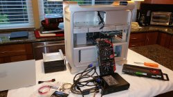
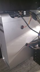
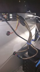
Here's what I did: MSI Gaming R9 280X 3G ... then sent to MVC for him to flash and on the alternate BIOS switch setting a custom OC flash ... Bought ePower 450W external GPU PSU. Decided to mod a spare Mac Pro side cover to allow cables to run into it. Pics attached
 

Attachments

  • 20141026_175533 (1).jpg
    20141026_175533 (1).jpg
    1.1 MB · Views: 906
  • 20141028_183823-1 (1).jpg
    20141028_183823-1 (1).jpg
    986.1 KB · Views: 610
  • 20141028_183855-1 (1).jpg
    20141028_183855-1 (1).jpg
    842.4 KB · Views: 603
  • 20141025_025400 (1).jpg
    20141025_025400 (1).jpg
    975.4 KB · Views: 666
Denis,

Just out of curiosity, did you measure the resistance between the two 12V lines before soldering the wire?

I only ask because it feels unlikely that the two wouldn't be connected directly together right on the board, making the wire superfluous. Of course, it's possible that they do go to separate sections of the board, etc., and hence are unconnected at the power connectors, at which point your "load re-distribution" wire could make sense.

Regardless, I admire the creative thought that went into the move.

(P.S., my tongue-in-cheek solution to this problem is: "don't run power viruses like Furmark!")

Cheers.
 
Last edited:
I'm very sure I did. But even if not, if both lines were connected booth boosters would show more or less the same value (Ampere) which they did not. After my patch they do show the same value. Also before I soldered the wire I connected both 12V lines through an ampere meter and it showed 2-3A.

I even thought about to solder another wire to the place at the card where the pci 12V line is arriving because the pci line is not that stressed. But I did not find the right place.

The best thing would be if the 6 pin cable and the 8 pin cable has the connection so the graphicscard and the macpro is still unmodified.

Denis
 
Hi Denis,

I looked at my 280X (MSI) and confirmed that there is a non-trivial impedance between the two power inputs (on my board).

As a warning to others, note that on my board, the power traces were on the bottom row, not the top.

I can't recommend that people do this unless they are very sure of what they are getting into.

Cheers.
 
On my MSI R9 280X v.1.1 board, there is just barely enough room to put a wire between the terminals you detailed, the standoffs to mount the 6-pin and 8-pin ports are directly above the terminals.

Would you say that a certain gauge of copper wire is required?
 
I'm not sure who you are asking, but I'll chime in:

Copper, and the heavier the better. I'd suggest multi-stranded and silicone jacketed. There is not just one power pin per connector, and note also that configurations differ - a middle pin might be a "sense" line instead of a power line. There are other pitfalls and questions as well.

Although I admire the creativity and ambition of the O.P., and it apparently worked for him, I do NOT recommend doing this! This is one of those "if you have to ask" then don't do it kinds of things. And you asked, so...
 
An older Thread but:

Why no 2x6 pin to 1x8 Pin Adapter and then connect a 1x8 Pin to 2x6+2 Pin adapter to this? then you have the bridge inside the cable. Is this a solution that will work?
 
Yes, that should work too. You can check the load with HWMonitor before and after to confirm that it works.

Denis
 
Why no 2x6 pin to 1x8 Pin Adapter and then connect a 1x8 Pin to 2x6+2 Pin adapter to this? then you have the bridge inside the cable. Is this a solution that will work?
Did you have any luck with this? Wouldn't that leave a 2 Pin adapter dangling?
 
This was my solution for a Titan X (eVGA Powerlink), but the card need connectors on the side turned away from the PCIe, near the corner like this card http://images.bit-tech.net/content_...60x-reviews/amd-radeon-r9-270x-03-300x292.jpg.
kk.jpg


The the cable solution also work, but with the long cable you will get a high electrical resistance (the 8 to 2x6 is in use).
kk2.jpg


Because of missing drivers im using a X580 with 2x6pin today.
 
Last edited:
Thank you for the response. Does the eVGA Powerlink act as a bridge? I have a R9 280x (6&8 pin) that I need to run to the 2 6pin connectors on the 5,1 motherboard board.
 
My RX 580 with EVGa PowerLink in bridge mode.

My reply post in another thread.

Post #53
://forums.macrumors.com/threads/compatible-rx580-8gb-brands-on-mac-pro-5-1.2217527/page-3?post=28131893#post-28131893
 
Register on MacRumors! This sidebar will go away, and you'll see fewer ads.