Become a MacRumors Supporter for $50/year with no ads, ability to filter front page stories, and private forums.

TragicManner

macrumors newbie
Original poster
Sep 17, 2007
6
0
Okay, so I have a G4 case that I've been modding to hold some newer hardware for Leopard. Kind of a crazy project, I know. I just love my G4 case, though. :D

The thing I need to know is, there is a circuit board that runs the LED, power button, reset button, etc in the case and I was wondering what the pinout was so I can split the cable out to be able to work with different main boards.

I searched a bit and couldn't find anything, so any help would be great!
 

OrangeSVTguy

macrumors 601
Sep 16, 2007
4,127
69
Northeastern Ohio
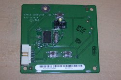
ok that's either a sawtooth or a gigabit ethernet, but they have the same board. i'll see if i can do a pinout for you. not making any promises though:p

added attachment...
this is the one you have, right?
 

Attachments

  • 100_4296.JPG
    100_4296.JPG
    543.4 KB · Views: 1,024
  • Like
Reactions: joeyslaptop

TragicManner

macrumors newbie
Original poster
Sep 17, 2007
6
0
Wait, I posted that that was it, but then I clicked on it and noticed it is quite a bit more complex than the one I have. Looks basically the same, though, so I'm sure a pinout for that specific part would be fine, at least good enough to point me in the right direction :D

Thanks!
 

nomar383

macrumors 65816
Jan 29, 2008
1,310
0
Rexburg, ID
I am doing a similar mod and would love a pinout for the GE front panel connections so I can hook it up to a standard mATX mobo
 

4JNA

macrumors 68000
Feb 8, 2006
1,505
1
looking for trash files
bassackwards...

i went the other way and put g4 guts in an ATX case, but same idea. what i came up with was to just solder a couple quick wires on the front panel board to connect to the case leads. yours should be even easier as you can just hook the ATX connectors to the existing pins.

edit; or better yet, leave the board connector end alone and splice the wires at the motherboard connector end. wow, it's late and i'm tired! so then trace out the common, the reset, and the power button and splice on standard connectors. the power light i would replace with a standard LED, and then jump the trace (bypass the chip/resistor) that is used for the sleep throbber thing.

atx case.jpg

front panel brd.jpg

the black wire is common, and you would need two for the power and reset. i also can see from the pics, that my older sawtooth board has different traces than the pic posted above, so just double check your work! best of luck, i'll try to help if i can, but i just traced the leads, ran the wires, took the pictures, and forgot all about it... :eek:
 

nomar383

macrumors 65816
Jan 29, 2008
1,310
0
Rexburg, ID
I really don't mean to hijack this thread, but could you explain how to make the connection a little better? I have done next to no soldering or electrical work before, so a detailed explanation and list of required tools would be real cool
 

nomar383

macrumors 65816
Jan 29, 2008
1,310
0
Rexburg, ID
Wait, I can just buy a standard connector and splice the original wires into it? Will that even require any soldering?
 

4JNA

macrumors 68000
Feb 8, 2006
1,505
1
looking for trash files
Wait, I can just buy a standard connector and splice the original wires into it? Will that even require any soldering?

correct. leave the front panel board end of the cable as is, trace out the switch or switches and/or LED lead that you want to use, and splice standard wire/connectors on the logic board end. you still need to trace out the correct pins/wires, but should be easy enough even without a multimeter if you don't have one.

this is not my pic, but for a visual it might help...

cable.jpg
 

nomar383

macrumors 65816
Jan 29, 2008
1,310
0
Rexburg, ID
One more question that might sounds stupid, how do I know which wires are what? Does the actual board have writing on it that might give me a clue? (I haven't taken the front panel apart to check it out yet)
 

4JNA

macrumors 68000
Feb 8, 2006
1,505
1
looking for trash files
fear my paint 5ki11z

...how do I know which wires are what?

as above, trace the circuit lines out, or better yet get a cheap multimeter (device for testing circuits). it beeps or shows you when you are one the same lead, so you can tell which lead goes with which pin. POS $7.97 meter at radio shack, but you might find something cheaper at harbor freight, or the clearance tool table at a hardware store, etc. if you are geeky and broke, you might try using a battery, some wire and a small flashlight bulb to find the correct pins...:cool:

with a meter, use the ohm (resistance) or diode check setting to find the correct pin. if that doesn't make any sense, then you might need to find some hands on help locally. using paint i traced the circuits...

100_4296.JPG

yellow is the common lead for all three switches, blue shows the actual pin for the reset switch, red is the power switch. can't tell from the pic which pin to use for red or yellow, so you need the meter to find out. for the LED, don't know anyway to solve it except solder. maybe break the old one off and tape an LED on the board in the spot so it shines out of the power switch?
 

OrangeSVTguy

macrumors 601
Sep 16, 2007
4,127
69
Northeastern Ohio
Heh! This is kinda an older thread. Sucks that I even wrote down some of the pinouts but not all of them back then. I'll let you know if I find it, but I doubt it, probably got thrown away already :(.

I don't even think I have the boards anymore to test them out.
 

nomar383

macrumors 65816
Jan 29, 2008
1,310
0
Rexburg, ID
Two more questions before I attempt this:

1. Should I just pull the little connectors that go to the mobo from an old PC that had a standard ATX front panel setup?

2. I should be checking for a total of 6 connections from the original panel correct? That is: a (+) and a (-) for the common, power and reset? Or am I misunderstanding?
 

4JNA

macrumors 68000
Feb 8, 2006
1,505
1
looking for trash files
Two more questions before I attempt this:

1. Should I just pull the little connectors that go to the mobo from an old PC that had a standard ATX front panel setup?

2. I should be checking for a total of 6 connections from the original panel correct? That is: a (+) and a (-) for the common, power and reset? Or am I misunderstanding?

yep, grabbing some from an old case/setup is what i would do. have a bunch here if you can't find anything local. the older ones had individual leads for the different connectors and that would work better than the newer all-in-one black block thingy.

and no to #2. the original front panel board has only 1 common line (see paint pic above) and 1 power switch lead, and 1 reset lead. so, you are actually only looking for 3 wires out of the gray front panel cable. for pwr/reset, hook the (-) leads to the front panel common line (yellow pin), and then hook the pwr/rst (+) to the individual pins for the front panel power and reset switches (blue pin and red pin above).

edit: time for more badass paint pics...:eek: and i have no idea which 3 gray wires, this is just a visual...

wires.JPG

if you look on the ATX motherboard (or in the manual) you have 3 connections to work on. power (pwr), reset (rst), and the power LED (or pwr_led). on most ATX motherboards, the power/reset leads are 2 pins next to each other (O O), and the power LED leads are a block of 3 (usually use the 2 outside pins and ignore the center, or O x O).

i still think if you plan to do this without solder, you might also look for an existing LED from an ATX case. most of the older cases had plastic holders, and you can break open the holder and remove the led with the leads/wires already soldered on. cut/break the existing front panel LED thingy out of the way, and tape/glue the new one in the same place would be the easiest fix i think. just for fun, you could hook the new led to the hard drive LED (hd_led) leads on the motherboard instead of the power LED leads. i don't know about you, but i can hear if the computer is on, and i'd rather see hard drive activity so i can tell if it's hung again... and would look cool flashing behind the power button. anyway, best of luck.
 

4JNA

macrumors 68000
Feb 8, 2006
1,505
1
looking for trash files
do I have to bother with the power led at all? could I just hook up the power and reset to be done?

what you want to hook up is up to you...:confused:

if you don't use reset, you could just hookup the power switch and be done. the new motherboard could care less if anything is hooked up, it's just easier to push a button than to open the case and short across a couple pins with a screwdriver when you want to start the computer...;)

or if you don't want to trace out the power switch lead, you could just use the reset switch as a power switch since we can see the pin (blue) in the pic. nothing magic about the board/switches. hook what you want to whatever you choose.
 

nomar383

macrumors 65816
Jan 29, 2008
1,310
0
Rexburg, ID
Okay, so I have a few more concerns lol

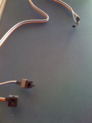
I picked up a few switches from an old regular front panel (shown below). I just attached them to the mobo to see if they would work to turn it on. When I press the button, I can see the powersupply come to life, but there doesn't seem to be any response from the mobo. It doesn't make a sound and I can't see any lights. Is this normal behavior? To be clear, I currently have no processor, RAM, HDs, or optical drives hooked up; just power.

It seems to me that if the powersupply turns on when I press the front panel button, then the mobo must be okay, but I dunno. Any comments?
 

Attachments

  • IMG_0010.jpg
    IMG_0010.jpg
    224.1 KB · Views: 667

joeyslaptop

macrumors newbie
Oct 24, 2007
8
3
ok that's either a sawtooth or a gigabit ethernet, but they have the same board. i'll see if i can do a pinout for you. not making any promises though:p

added attachment...
this is the one you have, right?

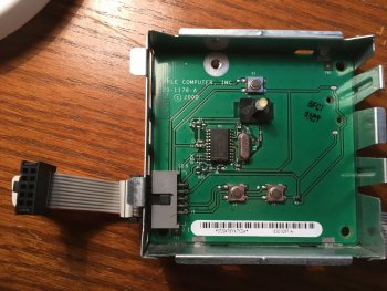
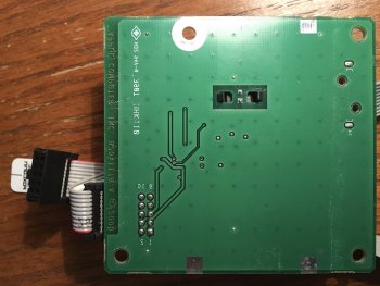
Do you have instructions or schematics for the power board (820-1178-A)? I'm trying to keep my mod as vanilla as I can, and really want to be able to get the power button to work as it did originally.

To use the front-panel speaker, I pulled apart a usb headset cable for the little sound card on it. Then I soldered that to a tiny USB amp for a USB speaker. Then I wired that to the speaker. So, my front-panel speaker is powered off one of the USB headers of my motherboard. The components are tucked neatly away in the speaker casing. So, now, I have normal audio through the front panel speaker just like it originally had.

I'm willing to do something similar in order to get my power button and led to function as well.

Any ideas or resources you can point me to?

(Note that the 2nd image is mirrored/reversed so that you can see how the top side of the card aligns with the bottom side of the card.)
 

Attachments

  • IMG_2800.JPG
    IMG_2800.JPG
    505.6 KB · Views: 352
  • IMG_2801.jpg
    IMG_2801.jpg
    377.9 KB · Views: 219
Last edited:

retta283

Suspended
Jun 8, 2018
3,180
3,482
Do you have instructions or schematics for the power board (820-1178-A)? I'm trying to keep my mod as vanilla as I can, and really want to be able to get the power button to work as it did originally.

To use the front-panel speaker, I pulled apart a usb headset cable for the little sound card on it. Then I soldered that to a tiny USB amp for a USB speaker. Then I wired that to the speaker. So, my front-panel speaker is powered off one of the USB headers of my motherboard. The components are tucked neatly away in the speaker casing. So, now, I have normal audio through the front panel speaker just like it originally had.

I'm willing to do something similar in order to get my power button and led to function as well.

Any ideas or resources you can point me to?

(Note that the 2nd image is mirrored/reversed so that you can see how the top side of the card aligns with the bottom side of the card.)
This thread hasn't been posted in since 2008, so it's unlikely that they are still around. Try posting in the PowerPC Macs board here, they should be able to give you some help.
 
  • Like
Reactions: joeyslaptop

NCC74656

macrumors newbie
May 12, 2022
14
1
i thought id post up here. i just retrofitted this smaller (rectangle) power board into an old performa case. it uses 3.3 and 5v reference rails and a resistive (MUX) style output from the logic controller on the board.
you can use a meter to trace back where things connect but there is no direct two pin short (like you would see on a PC) for the front panel connectors.

the buttons are a DPDT style (two circuits get energized when activating). there are small white dots by the pads at the buttons that indicate the primary function output of the switch. they pin out diagonally to a common circuit bus (but its not ground).

you have two options to interface. #1 - leave the board intact and solder directly to the buttons to emulate them being pushed (closing the circuit with an external device)
#2 - pullup the schematic on digikey (the controller is still an active part) and build an external project board to utilize/emulate the same i/o at the processor level. the board has a clock crystal and an Rx/Tx to sniff and spoof for activation. a bus sniffer that can read real time bus data (or quality two channel scope with decode features) is perfect for this.

it took me about three hours to get the circuit working how i wanted.

also, the back 1/3 of the mac's board (where you do not see any traces) is blank. it has a ground plane in it but no power that i could find. you can band saw or hack saw parts out of the PCB to make it fit anywhere you may need.
 
Register on MacRumors! This sidebar will go away, and you'll see fewer ads.