Help, my iMac 21.5 (2013 model) has been working without problems since purchase in 2013. However, today while downloading an upgrade for Office 360 for Mac, a fuse suddenly blew in the house. After investigating, it proved to be the same circuit my iMac was connected to. I tried unplugging/plugging my iMac in various outlets and it blew a fuse every time. How can this be?? Is it possible that downloaded software can damage the internal power hardware of my iMac? Anyone experience a similar problem? My iMac is totally useless right now.
Got a tip for us?
Let us know
Become a MacRumors Supporter for $50/year with no ads, ability to filter front page stories, and private forums.
iMac 21.5 inch blows home fuse
- Thread starter Rgrindheim
- Start date
-
- Tags
- imac power
- Sort by reaction score
You are using an out of date browser. It may not display this or other websites correctly.
You should upgrade or use an alternative browser.
You should upgrade or use an alternative browser.
Your power supply blew. The software download was just a coincidence, it would have happened either way at that very moment regardless of what you were doing.
Could be the iMac's power cord?
Or perhaps an internal short in the power supply?
(mj posted his reply while I was typing this one!)
Or perhaps an internal short in the power supply?
(mj posted his reply while I was typing this one!)
I tried another power cord without success.☹️ Must be a problem with the internal power supply. Probably difficult to buy a new power supply here in Norway but I will have a look.Could be the iMac's power cord?
Or perhaps an internal short in the power supply?
(mj posted his reply while I was typing this one!)
[automerge]1585840844[/automerge]
Thanks, Fishrrman, I presume you are right. Probably difficult and expensive to buy a new power supply here in Norway. I may have to look into buying a new iMac.😥Your power supply blew. The software download was just a coincidence, it would have happened either way at that very moment regardless of what you were doing.
Buying a new mac for a faulty PSU sounds like overkill to me.I tried another power cord without success.☹ Must be a problem with the internal power supply. Probably difficult to buy a new power supply here in Norway but I will have a look.
[automerge]1585840844[/automerge]
Thanks, Fishrrman, I presume you are right. Probably difficult and expensive to buy a new power supply here in Norway. I may have to look into buying a new iMac.😥
You can easily get a second hand power supply at eBay (please check compability yourself); you will also need new adhesive strips for the screen. Which is the ‘hard’ part, opening up the iMac due to the adhesive sealing.
Swapping the power supply itself takes roughly 2 minutes with a screw driver.
NB In a best case scenario you might not even need a new PSU, but can swap out any dead caps on the old one.
DO NOTE This requieres soldering skills and CAUTION, since the PSU is high voltage.
Buying a new mac for a faulty PSU sounds like overkill to me.
You can easily get a second hand power supply at eBay (please check compability yourself); you will also need new adhesive strips for the screen. Which is the ‘hard’ part, opening up the iMac due to the adhesive sealing.
Swapping the power supply itself takes roughly 2 minutes with a screw driver.
NB In a best case scenario you might not even need a new PSU, but can swap out any dead caps on the old one.
DO NOTE This requieres soldering skills and CAUTION, since the PSU is high voltage.
Thanks, Jumme_Cph, swapping the PSU does sound like a good idea. I’m just a little concerned that there could be further damage. I will however look into getting a new PSU here in Norway If I can find a reasonable used one.
Just beware that you will have to open up your imac and need these adhesive strips to put it back together.Thanks, Jumme_Cph, swapping the PSU does sound like a good idea. I’m just a little concerned that there could be further damage. I will however look into getting a new PSU here in Norway If I can find a reasonable used one.
I would personally choose to open it up before ordering the part for two reasons; a) that you might be able to visually see the defective part (typically a bulged capasitor or burned area) - and b) that you might see damage inside already before reaching the PSU.
Eg. is the power lines on the back of the 220v socket all intact..?
Also, from your description it doesnt sound like the iMac is too much good to you anyway right now.
As the “back side” of the PSU (everything inside the imac) is all low voltage, I would higly doubt that an defect here would shortcut your home installation/fuse - it would just have shortned out and not turn on again. Basically speaking. IMO.
Last edited:
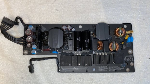
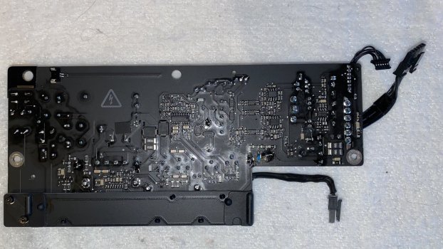
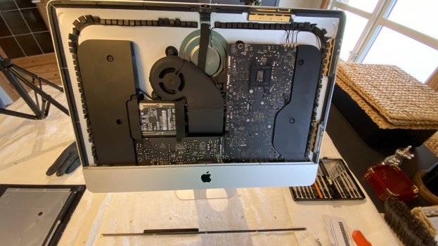
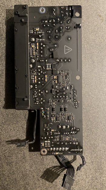
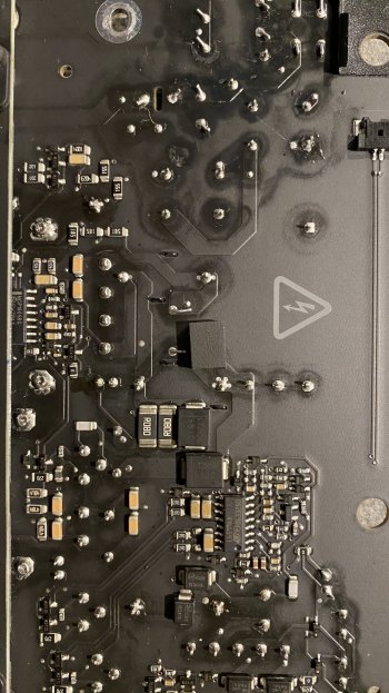
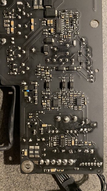
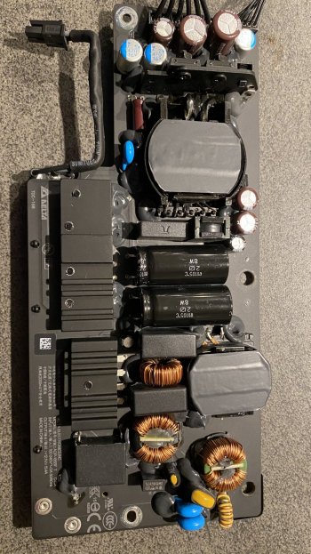
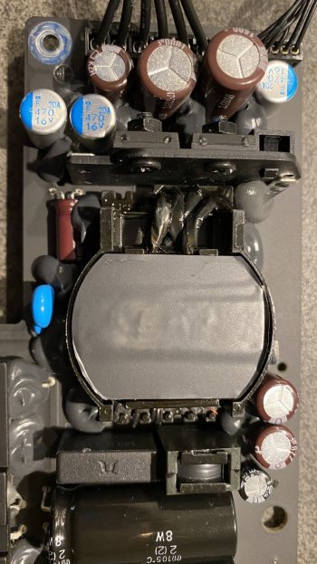
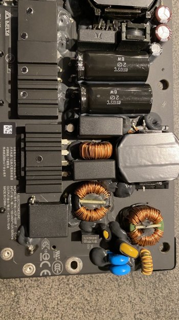
Just thought I would return with the latest info. I actually managed to pick up a used iMac identical to my old one for only 4000 NOK which is working fine. However, now that I have a working iMac and time to really look at the old one, I want to see if I can repair it and have it as a back-up iMac. I have ordered a new PSU from eBay which should arrive any day now. In the meantime, I have removed the screen and the old PSU. I can’t see any damage to the PSU card. All capacitors seem OK and I can’t see any burn marks. The 6.3A fuse on the PSU card is intact (not blown). I even plugged in the standalone PSU card to see if the house fuse blew when it’s not connected to the motherboard etc and yes - the house fuse blew again. This is strange as the house fuse is 16A. Why does the house fuse blow before the PSU fuse? It would’ve been nice if I could just replace a capacitor. I’ll let you know how things go once I install the new PSU card. Attaching a few photos.Just beware that you will have to open up your imac and need these adhesive strips to put it back together.
I would personally choose to open it up before ordering the part for two reasons; a) that you might be able to visually see the defective part (typically a bulged capasitor or burned area) - and b) that you might see damage inside already before reaching the PSU.
Eg. is the power lines on the back of the 220v socket all intact..?
Also, from your description it doesnt sound like the iMac is too much good to you anyway right now.
As the “back side” of the PSU (everything inside the imac) is all low voltage, I would higly doubt that an defect here would shortcut your home installation/fuse - it would just have shortned out and not turn on again. Basically speaking. IMO.
Attachments
Im no electric ingeneer. But the fuse in your house blowing and an intact fuse in the PSU card could indicate a short BEFORE the PSU, eg in the back of the input socket (220v) or anywhere from the socket to the PSU.Just thought I would return with the latest info. I actually managed to pick up a used iMac identical to my old one for only 4000 NOK which is working fine. However, now that I have a working iMac and time to really look at the old one, I want to see if I can repair it and have it as a back-up iMac. I have ordered a new PSU from eBay which should arrive any day now. In the meantime, I have removed the screen and the old PSU. I can’t see any damage to the PSU card. All capacitors seem OK and I can’t see any burn marks. The 6.3A fuse on the PSU card is intact (not blown). I even plugged in the standalone PSU card to see if the house fuse blew when it’s not connected to the motherboard etc and yes - the house fuse blew again. This is strange as the house fuse is 16A. Why does the house fuse blow before the PSU fuse? It would’ve been nice if I could just replace a capacitor. I’ll let you know how things go once I install the new PSU card. Attaching a few photos.
PROCEED AT OWN RISK:
you might try CAREFULLY Placing the PSU on an non-conductive layer, like a big plastic cutting board.
Then, turn of power on the wall/eject 220v cord.
Then, somehow connect the 220v cord with the 220v INPUT of the PSU directly. Then, connect 220v cord to wall/turn on power.
Now you should have the PSU connected directly to the 220v power socket. Turn on. DO THIS AT OWN RISK.
a) the fuse blows: The fault is in PSU
b) fuse doesn’t blow = the short causing the fuse blowing is DEFINITELY between the power socket on the back of the Mac, and the PSU.
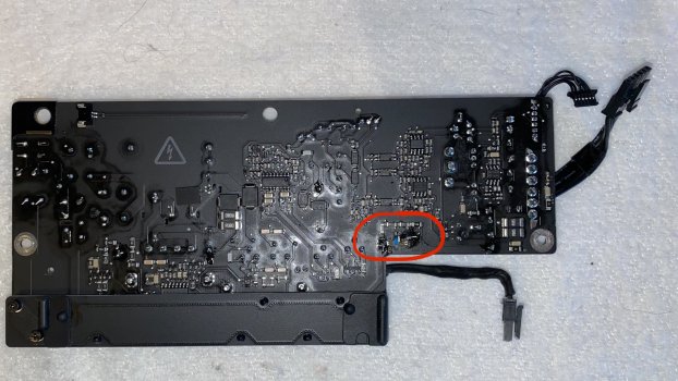
By the way, would you be so kind as to post a really good close up image of this area of the PSU.
I might just be the lighting on above image; but something seems really wrong there....
Plz upload high resolution picture online, and with really good lighting.
NOTE: TAKE CARE WHEN HANDLING THE PSU. IT CAN POTENTIALLY KILL YOU, AND SEVERAL PARTS CONTAINS HIGH VOLTAGE 400V - EVEN SEVERAL HOURS AFTER YOU DISCONNECT THE PSU FROM MAINS. DO NOT PROCEED IF YOU DONT KNOW WHAT TO TOUCH!!!
Attachments
Last edited:
Thanks for your quick reply.Im no electric ingeneer. But the fuse in your house blowing and an intact fuse in the PSU card could indicate a short BEFORE the PSU, eg in the back of the input socket (220v) or anywhere from the socket to the PSU.
PROCEED AT OWN RISK:
you might try CAREFULLY Placing the PSU on an non-conductive layer, like a big plastic cutting board.
Then, turn of power on the wall/eject 220v cord.
Then, somehow connect the 220v cord with the 220v INPUT of the PSU directly. Then, connect 220v cord to wall/turn on power.
Now you should have the PSU connected directly to the 220v power socket. Turn on. DO THIS AT OWN RISK.
a) the fuse blows: The fault is in PSU
b) fuse doesn’t blow = the short causing the fuse blowing is DEFINITELY between the power socket on the back of the Mac, and the PSU.
By the way, would you be so kind as to post a really good close up image of this area of the PSU.
I might just be the lighting on above image; but something seems really wrong there....
Plz upload high resolution picture online, and with really good lighting.
NOTE: TAKE CARE WHEN HANDLING THE PSU. IT CAN POTENTIALLY KILL YOU, AND SEVERAL PARTS CONTAINS HIGH VOLTAGE 400V - EVEN SEVERAL HOURS AFTER YOU DISCONNECT THE PSU FROM MAINS. DO NOT PROCEED IF YOU DONT KNOW WHAT TO TOUCH!!!
I probably didn't explain it well but I did as you outlined and removed the PSU completely from the iMac and connected (using paper clips etc) it directly to the wall socket (230V, 16A). The house fuse blew every time and at any socket - so as you conclude in a) above, the fault is somewhere in the PSU. I tried poking around with a multimeter but could not find a major short in the PSU. Measuring between the 2 pins were 230V enters the PSU showed approximately 1.5 Mohm (no shortage). Really weird, I expected to see 0 ohms since the house fuse blows when connected. Also, I could not see any "bulging" capacitors. Unfortunately, I am not an electrical engineer either so I'm mostly playing around. Attaching new photos with better lighting.
Attachments
Just checking: Did you already check the fuse (last picture, square next to 2 blue caps, marked "T6.3A.250V" for continuity??Thanks for your quick reply.
I probably didn't explain it well but I did as you outlined and removed the PSU completely from the iMac and connected (using paper clips etc) it directly to the wall socket (230V, 16A). The house fuse blew every time and at any socket - so as you conclude in a) above, the fault is somewhere in the PSU. I tried poking around with a multimeter but could not find a major short in the PSU. Measuring between the 2 pins were 230V enters the PSU showed approximately 1.5 Mohm (no shortage). Really weird, I expected to see 0 ohms since the house fuse blows when connected. Also, I could not see any "bulging" capacitors. Unfortunately, I am not an electrical engineer either so I'm mostly playing around. Attaching new photos with better lighting.
Besides that, I would give up if not able to inspect visual damage! It could be any part, both covered under silicone or under a heat sink. Any local electrical repair shop might be able to restore the unit, but question is, if its worth the price. Personally I hate to give up, but I also take care to respect my limits. The PSU is potentially hazardous and might catch on fire at a later point.
Good luck either way, and keep us updated in case of any progress.
Oh yeah, I checked the fuse and there was full continuity. I'm just like you and hate to give up.🙂 Hopefully, the new PSU will arrive shortly so I can install it get the old iMac up and running again. Still, I´d like to rescue the old PSU. Maybe I can find some electronics geek among my friends who may be able to fully test the old PSU. I`ll keep you posted.Just checking: Did you already check the fuse (last picture, square next to 2 blue caps, marked "T6.3A.250V" for continuity??
Besides that, I would give up if not able to inspect visual damage! It could be any part, both covered under silicone or under a heat sink. Any local electrical repair shop might be able to restore the unit, but question is, if its worth the price. Personally I hate to give up, but I also take care to respect my limits. The PSU is potentially hazardous and might catch on fire at a later point.
Good luck either way, and keep us updated in case of any progress.
I'm electrical engineer, maybe I can help.
I have done analysis of the 2009-2011 power supply here.
There can be several causes for your fault pattern. If you have a multimeter it might be possible to find the faulty component. But without schematics, it is difficult. I drew my own for my model, of course I do not have one for yours. The AC input side will very like be quite similar to mine.
First suspect is the capacity across the input. Your also have that. They sometime become low ohmic, but you measured this already.
I suspect either one of your power MOSFETs is shorted, or the PFC IC, or soft start IC. Not sure you have them all.
To check which section got the problem, you can unsolder one of the components that is in series. Check the bridge rectifier which is connected before the high voltage capacitors.
You might get some info here, too: Link to ADP185BF thread
Last edited:
Hi, and thanks for your input. Wish I had a schematics of my model but no such luck. In addition, it mostly above my head. I am trying to localise the problem with my multimeter but not sure I'm doing things right. I am however tending to think the the "bridge rectifier" may be the culprit. I think it may be a GBU806 (GC36) model (see attachment). I need to remove it to be sure but haven't done the yet. Need to get some soldering equipment. Keep you posted-I'm electrical engineer, maybe I can help.
I have done analysis of the 2009-2011 power supply here.
There can be several causes for your fault pattern. If you have a multimeter it might be possible to find the faulty component. But without schematics, it is difficult. I drew my own for my model, of course I do not have one for yours. The AC input side will very like be quite similar to mine.
First suspect is the capacity across the input. Your also have that. They sometime become low ohmic, but you measured this already.
I suspect either one of your power MOSFETs is shorted, or the PFC IC, or soft start IC. Not sure you have them all.
To check which section got the problem, you can unsolder one of the components that is in series. Check the bridge rectifier which is connected before the high voltage capacitors.
You might get some info here, too: Link to ADP185BF thread
Attachments
How to check the bridge rectifier: put your multimeter in 'diode' mode. This will test the forward voltage. You test between the '~' and '+'. You should see a value (e.g. 300 to 700, depending on whether this is schottky or silicon rectifier) when red probe is on '+' and black probe is on '~'. When you reverse the probes, you should not see a value respectively OL (over limit).
Then check between '~' and '-'. This time, you should see a value with black on '-' and red on '~', and OL when reversed. If you see a low value in both directions, the internal diode is blown.
You can apply this rule to each diode.
You can check the capacitors in Ohm setting. When first connecting the probes, the value might be low, but then rise continually as the capacitor is charging. Note that if you test capacitors in-circuit (i.e. you didn't desolder), you may have other components impacting on them, so in-circuit measurement isn't very reliable if you don't know the circuit. But it's a good start. Only if the values show very low ohmic (in the ohms or some 10 ohms range), i would desolder and check.
Your AC portion is nearly identical with mine, see schematic. You can identify the large 450V capacitors C6 and C7, indicated with + and -.
You can also find the two MOSFETS T1 and T3, and I indicated G,S,D.
The MOSFET (power transistor) has 3 pins.One is "Gate" (G), which is the control input. Normally, the circuit board track to this pin will be narrow/thin. The other 2 pins are "Drain" (D) and "Source" (S). The PCB tracks to these pins will be wide/thick. However, on your board, the thick tracks are all concealed by the heatsink, so it is difficult to tell which pin is what. But you can still check the mosfets relatively easily, when you consider how they are connected.
T1 will switch the "+" 300V to the common pin of the transformer winding, and T3 will switch the nagative line (actually 0V, GND). You can see that S of T1 and D of T3 are together on this winding. So in your circuit, check which S and D are together, and you know which one is T1 and which one T3. To confirm, check that D of T1 goes to + of the capacitors, and S of T3 goes to - of the capacitors.
If you measure diode between D and S, it likely behaves like a diode, see behavior above. Check Ohms, too. If you see ~0 Ohms in both directions, this is spoilt.
Between G and S, you will see the 10kOhm resistor (marking: 103), or even lower ohms. Between G and D, it should be high ohmic (Megaohm).
If you have done those components, I would hope that you have found the culprit.
Sometimes also the diode on the secondary side short circuits. These are often 3-pin components (double diodes) with large heatsink. In the schematic, it is D3 & D5. check each of them.
Yours are two double-diodes, standing, with the heatsink, next to the 3 brown and 2 silver/blue capacitors. Check each of them. The middle pin (2) is common. So pin 1 and 3 should have a diode behavior towards pin 2.
oh somebody also like me . but my thread nobody reply. for now im not sure to buy psu for my imac 2017 baseline.Just thought I would return with the latest info. I actually managed to pick up a used iMac identical to my old one for only 4000 NOK which is working fine. However, now that I have a working iMac and time to really look at the old one, I want to see if I can repair it and have it as a back-up iMac. I have ordered a new PSU from eBay which should arrive any day now. In the meantime, I have removed the screen and the old PSU. I can’t see any damage to the PSU card. All capacitors seem OK and I can’t see any burn marks. The 6.3A fuse on the PSU card is intact (not blown). I even plugged in the standalone PSU card to see if the house fuse blew when it’s not connected to the motherboard etc and yes - the house fuse blew again. This is strange as the house fuse is 16A. Why does the house fuse blow before the PSU fuse? It would’ve been nice if I could just replace a capacitor. I’ll let you know how things go once I install the new PSU card. Attaching a few photos.
no time for opera . I would have one if exist . A trip electric each time on imac is not a joke. I used avr also before.Don't make an epic opera out of this.
Replace the power supply.
If it works, throw the old one away.
If the iMac still blows the fuse (with a new power supply), put it into the closet or recycle it.
** no m1 mac mini available and the imac put in their original box. My alternative is old macbook 2011 and new huawei d15 ryzen.
How to check the bridge rectifier: put your multimeter in 'diode' mode. This will test the forward voltage. You test between the '~' and '+'. You should see a value (e.g. 300 to 700, depending on whether this is schottky or silicon rectifier) when red probe is on '+' and black probe is on '~'. When you reverse the probes, you should not see a value respectively OL (over limit).
Then check between '~' and '-'. This time, you should see a value with black on '-' and red on '~', and OL when reversed. If you see a low value in both directions, the internal diode is blown.
You can apply this rule to each diode.
You can check the capacitors in Ohm setting. When first connecting the probes, the value might be low, but then rise continually as the capacitor is charging. Note that if you test capacitors in-circuit (i.e. you didn't desolder), you may have other components impacting on them, so in-circuit measurement isn't very reliable if you don't know the circuit. But it's a good start. Only if the values show very low ohmic (in the ohms or some 10 ohms range), i would desolder and check.
Your AC portion is nearly identical with mine, see schematic. You can identify the large 450V capacitors C6 and C7, indicated with + and -.
You can also find the two MOSFETS T1 and T3, and I indicated G,S,D.
The MOSFET (power transistor) has 3 pins.One is "Gate" (G), which is the control input. Normally, the circuit board track to this pin will be narrow/thin. The other 2 pins are "Drain" (D) and "Source" (S). The PCB tracks to these pins will be wide/thick. However, on your board, the thick tracks are all concealed by the heatsink, so it is difficult to tell which pin is what. But you can still check the mosfets relatively easily, when you consider how they are connected.
T1 will switch the "+" 300V to the common pin of the transformer winding, and T3 will switch the nagative line (actually 0V, GND). You can see that S of T1 and D of T3 are together on this winding. So in your circuit, check which S and D are together, and you know which one is T1 and which one T3. To confirm, check that D of T1 goes to + of the capacitors, and S of T3 goes to - of the capacitors.
If you measure diode between D and S, it likely behaves like a diode, see behavior above. Check Ohms, too. If you see ~0 Ohms in both directions, this is spoilt.
Between G and S, you will see the 10kOhm resistor (marking: 103), or even lower ohms. Between G and D, it should be high ohmic (Megaohm).
If you have done those components, I would hope that you have found the culprit.
Sometimes also the diode on the secondary side short circuits. These are often 3-pin components (double diodes) with large heatsink. In the schematic, it is D3 & D5. check each of them.
Yours are two double-diodes, standing, with the heatsink, next to the 3 brown and 2 silver/blue capacitors. Check each of them. The middle pin (2) is common. So pin 1 and 3 should have a diode behavior towards pin 2.
View attachment 1676323
View attachment 1676325
Thanks for you thorough troubleshooting guideline, USB3foriMac. Very impressive. I'm a retired mechanical engineer so much is still new territory for me but curiosity pulls me in.
I revert with results from the checks I was able to perform as follows:
1 BRIDGE RECTIFIER
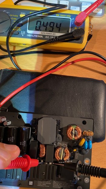
All diode checks of the rectifier "in-circuit" gave approximately 0.49V in both directions. Perhaps this is because it is "in-circiut"? Or perhaps it is blown (I think it may be). See photo.
2 MOSFETS
Initial check indicates that T1 is the MOSFET to the right in your photo. Diode check between D and S gave approximately 0.45V both directions. Ohm check gave 3.85MΩ in one direction and 0.73MΩ in the other direction. Not sure what this means.
3 DOUBLE DIODES
These seem to check out with approximately 0.65V in one direction and OL in the other direction.
Just to clarify - all checks are performed "in-circuit". I haven't un-soldered anything yet. I think I may un-solder the bridge rectifier next weekend and see exactly which model/size it is.
Attachments
Nope, from ~ to +, there should be 0.5V only in one direction, and OL in the other. Same from ~ to -.1 BRIDGE RECTIFIER
All diode checks of the rectifier "in-circuit" gave approximately 0.49V in both directions. Perhaps this is because it is "in-circiut"? Or perhaps it is blown (I think it may be). See photo.
However if the rectifier was bad, you would see 0V. There is another component somewhere causing this.
When measuring in "Diode" mode, the multimeter will use a small current, typically below 1mA, and measure the voltage at which this current will flow. So the voltage delivered by the multimeter will vary depending on the external component.2 MOSFETS
Initial check indicates that T1 is the MOSFET to the right in your photo. Diode check between D and S gave approximately 0.45V both directions. Ohm check gave 3.85MΩ in one direction and 0.73MΩ in the other direction. Not sure what this means.
When measuring in Ohm mode, the multimeter will apply typically a current depending on the measuring range, such as shown here (from Fluke 87-V, Range / measuring current):
Digital multimeter will always start with the lowest current, so this will give varying results when semiconductor or capacitive components are measured.
The Mosfet's diode is parasitic. Other than that, you should not have an ohmic connection from Drain to Source when non-conductive.
I'm pretty confident that those two indicated are T1 and T3, as they are so close together. However, there is another Mosfet, T2, towards the left (back side), just below the fat capacitors.
This one belongs to the Power Factor Correction chip NCP1605, IC1. check T2 same as T1/T3.
So this could be shorted, or IC1 could be blown and cause T2 to be conductive all the time.
Since IC1 will be difficult to check (if you want to attempt let me know), it would be easier to just unsolder T2. As this circuit is for PFC only, it is not relevant for the functional operation. If without T2 the circuit circuit works, you can continue using it. If T2 is shorted, you can replace it. If T2 is ok, IC1 is likely the culprit.
Hm, I think you may be on to something regarding T2. I measured T2 same as T1/T3 but all values were 0V. It seems there is basically zero ohm resistance between any of the 3 pins. Shorted? If T2 is shorted, can this cause my house fuse to blow?Nope, from ~ to +, there should be 0.5V only in one direction, and OL in the other. Same from ~ to -.
However if the rectifier was bad, you would see 0V. There is another component somewhere causing this.
When measuring in "Diode" mode, the multimeter will use a small current, typically below 1mA, and measure the voltage at which this current will flow. So the voltage delivered by the multimeter will vary depending on the external component.
When measuring in Ohm mode, the multimeter will apply typically a current depending on the measuring range, such as shown here (from Fluke 87-V, Range / measuring current):
View attachment 1677301
Digital multimeter will always start with the lowest current, so this will give varying results when semiconductor or capacitive components are measured.
The Mosfet's diode is parasitic. Other than that, you should not have an ohmic connection from Drain to Source when non-conductive.
I'm pretty confident that those two indicated are T1 and T3, as they are so close together. However, there is another Mosfet, T2, towards the left (back side), just below the fat capacitors.
View attachment 1677303 Check that one out, too.
This one belongs to the Power Factor Correction chip NCP1605, IC1. check T2 same as T1/T3.
So this could be shorted, or IC1 could be blown and cause T2 to be conductive all the time.
Since IC1 will be difficult to check (if you want to attempt let me know), it would be easier to just unsolder T2. As this circuit is for PFC only, it is not relevant for the functional operation. If without T2 the circuit circuit works, you can continue using it. If T2 is shorted, you can replace it. If T2 is ok, IC1 is likely the culprit.
There you go.Hm, I think you may be on to something regarding T2. I measured T2 same as T1/T3 but all values were 0V. It seems there is basically zero ohm resistance between any of the 3 pins. Shorted? If T2 is shorted, can this cause my house fuse to blow?
T2 is shorted, and of course this shorts out the circuit right after the rectifier. That's why you measure 0.6V at all sides of the rectifier. + and - are commoned by T2.
The glass fuse is too slow to blow, hence your house circuit breaker switches off much faster.
Just unsolder T2, or just cut the pins from the top side, and measure again. I'm fairly sure this is your only fault in the circuit and it will work again. There is no impact on function without having PFC. Main reason for PFC is to measure your power consumption more accurately.
Looks like you currently have a HDD in that iMac.
Seeing you have it open it would be a good idea to put a SATA III (6Gbps) SSD in it.
If the machine can be repaired an SSD will make it feel a lot faster, like having a significantly newer machine.
If the iMac cannot be repaired you would just open it up again and remove the SSD for use elsewhere.
Seeing you have it open it would be a good idea to put a SATA III (6Gbps) SSD in it.
If the machine can be repaired an SSD will make it feel a lot faster, like having a significantly newer machine.
If the iMac cannot be repaired you would just open it up again and remove the SSD for use elsewhere.
are it will the same board with 2017 or diff ? maybe next year i try to play around.There you go.
T2 is shorted, and of course this shorts out the circuit right after the rectifier. That's why you measure 0.6V at all sides of the rectifier. + and - are commoned by T2.
The glass fuse is too slow to blow, hence your house circuit breaker switches off much faster.
Just unsolder T2, or just cut the pins from the top side, and measure again. I'm fairly sure this is your only fault in the circuit and it will work again. There is no impact on function without having PFC. Main reason for PFC is to measure your power consumption more accurately.
Open a new thread (but not like the rant you did the other day), post highres and close-up pics of both sides, the model number of the supply, and then we all can see whether we can be of help.are it will the same board with 2017 or diff ? maybe next year i try to play around.
Register on MacRumors! This sidebar will go away, and you'll see fewer ads.


