Hi.....
the technician guy thinks the problem is that the new processor uses more power than the original and it pull it from other components in this case the capacitor that power the usb...
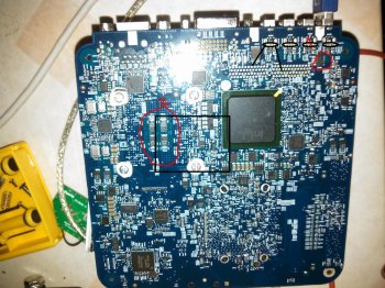
one capacitor that power the usb ports its giving 3.3v instead of 5v(figure 1 on image) and 4 capacitors near the processor are giving 1.3v and should be giving 3.2v aprox (figure 2 on image)
he has the idea that its going to disconnect the usb from that capacitor to another thing that gives 5v to power them up.....
what do you think? we havent tried putting back the original processor to see if the usb ports work again...he said nothing is burned or damaged that in theory it should work
View attachment 699365
I am suspicious of the reasoning. That 3.3V sounds like a digital-IO voltage, and if so, means that those capacitors are part of a filter for digital ICs nearby the USB port. Hence, those two larger capacitors may not be related to the 5V supply line of the USB ports. As for the 4 capacitors near the CPU, those are most definitely buffering the CPU core voltage line (Vcore) and should be around 1.3V. That is around the correct voltage for your Core 2 Duo CPU.
What I would recommend you do (or your technician), is to replace the CPU back to the older one, and test to see if the USB ports are putting out any power (use a USB flash drive with a LED, or a USB flashlight or whatever that has an indicator to demonstrate power on status).
Although the CPU TDP of the Core 2 Duo processor is more than the older Core Duo, it should not result in this situation, as the voltage regulator module (VRM) of the board is completely independent of the USB ports, which are controlled by the South Bridge (that big flat IC with the green edges in your photo). If your South Bridge does not work, then your mini should not power up at all.
Long story short - check that the USB ports are putting out power first, measure between the 5V (one of the pins soldered under the port, you may have to test all of them, but I'm pretty sure that it is either the leftmost or rightmost one in your pics, as you see 4 little solder joints below each USB port in your picture, two innermost ones are for the data+ and data-, so the outer two are 5V and return, test to see which is which, if there is any 5V at all) and the metallic sheath of the ports to check.
I have marked the pins of each USB port and identified the most probable solder pins for the 5V in the leftmost USB port position for you on the image you attached. See image, the black ovals mark each set of 4 solder pins per USB port and the two lines indicate the outer pins (test both to see if there is any thing close to 5V) for the leftmost USB port.


