Become a MacRumors Supporter for $50/year with no ads, ability to filter front page stories, and private forums.

DrBobF

macrumors newbie
Original poster
Mar 27, 2014
5
1
CT
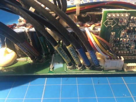
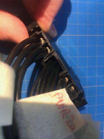
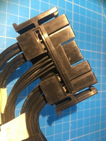
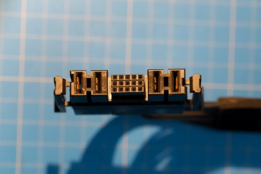
Greetings - I'm trouble shooting a 2009 Mac Pro for a no power up problem. The apple custom 980Watt delta power supply pinout is proprietary but the major power rail positions are evident. ( +12/ GND... GND/ +!2 ) The center group of smaller pins have two conductors that when shorted together will power on the PSU, which is, I think, the " power on" signal, normally supplied by the mother board. In the process of load testing the PSU on the bench to check the current spec.
Does anyone have the full pin out of these center group of conductors?

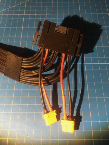
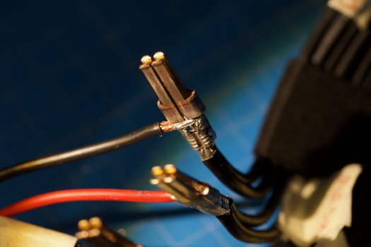
Update... I just did a quick load test on the PSU using a 100watt load on each of the 12V rails and forcing the PSU to turn on with the two pins I spoke of.
PSU seems to be working at this load and being when it is put back into the chassis with only the motherboard, front and rear panels installed with the 5VSB led lighting when the diagnosis button is pressed, it seems the the power on signal to the PSU is not happening. It seems either a connection issue on the mother board or a failure of the power on button/ circuit. A schematic would be handy to troubleshoot this.
 
Last edited:
  • Like
Reactions: yakult121

Macschrauber

macrumors 68030
Dec 27, 2015
2,948
1,471
Germany
this is all I got:

PSU on-1.jpeg
 

DrBobF

macrumors newbie
Original poster
Mar 27, 2014
5
1
CT
Thanks for the information. I just put the PSU on the test bench and shorted the two pins ( must be the "Power On" signal ) out and the PSU turns on. With a fractional load of ~100W on both the A and B outputs, the 12volt rails are stable. Must be a connection, motherboard or front panel issue. Without any of the proprietary ( Not even to developers ) schematics , it is time to get out the DDM and analyzer to see what is not happening. Thanks again. Cheers.
 

Macschrauber

macrumors 68030
Dec 27, 2015
2,948
1,471
Germany
A Mac Pro 5.1 board set runs without the front panel. I just put together a backplane board, prozessor board and of course a gpu, a usb boot device and got it booting. No fans, no front panel and no case. I just had to shorten the power on pads on the board.

Please share what you can sort out, i am too lazy now (without a reason) to put out a PSU for more measurings :)
 
  • Like
Reactions: h9826790

zcream

macrumors member
Sep 8, 2008
52
7
Thanks a ton. Any idea how that maps to the rails from the rear? I might connect to a molex connector by soldering from the rails
 

donluca

macrumors regular
Jul 30, 2018
193
94
Italy
Credit to Jason Ling Ling King.
View attachment 851601

Holy moly, this is a godsend, we can now try getting a Custom PSU together and see if it works! 4,1 and 5,1 PSUs are dying like flies those days and a proper PSU means having no needs to do pixlas mod, just route the cables!

Hopefully someone will get on this and shed some light, especially on the Pin 8 which supplies... 5.12V? Uhmmm...
 

Trail-Hawk

macrumors newbie
Jan 25, 2020
5
1
Any updates on this at all? Did you find the issue and was it the PSU? Currently have a 2012 pro tower, when AC is connected two red diag lights at the top of the back plane board come on and stay on. Perhaps after 5 mins go off. machine then takes a few power button presses - lots of clicking then will boot. All fans run full tilt. Will get into os however after about 2-3 mins will shut down. 12v power rails appear to fluctuate 12.2 to 12.4v approx and a small faint constant click from the PSU but hard to determine if that’s the actual fault at this point. Would be great to know what those diag lights are. I can find that particular code description anywhere. Thanks.
 

Snow Tiger

macrumors 6502a
Dec 18, 2019
854
634
Any updates on this at all? Did you find the issue and was it the PSU? Currently have a 2012 pro tower, when AC is connected two red diag lights at the top of the back plane board come on and stay on. Perhaps after 5 mins go off. machine then takes a few power button presses - lots of clicking then will boot. All fans run full tilt. Will get into os however after about 2-3 mins will shut down. 12v power rails appear to fluctuate 12.2 to 12.4v approx and a small faint constant click from the PSU but hard to determine if that’s the actual fault at this point. Would be great to know what those diag lights are. I can find that particular code description anywhere. Thanks.
What are the colors of the following LED diagnostic lights that stay on constantly ? Not worried about brief flashes . These two banks of lights are located on the upper left portion of the logic board

Mac Pro 4,1 and 5,1 ( Nehalem ) BackPlane Onboard LED Diagnostic Indicators :

Upper bank :

OVTMP CPUA
OVTMP CPUB
PSU PWROK
5V STBY
3.3V ( No light installed )
1.5V ( No light installed )
1.05V ( No light installed )


Lower bank :
SYS PG
PLT RS ( No light installed )
X1 PG ( No light installed )
EFI DONE
GPU OK
5V ( No light installed )
RSM RST ( No light installed )

During normal operation , the PSU PWROK is green , the 5V STBY is amber , the SYS PG is green and the EFI DONE is green .
 

Trail-Hawk

macrumors newbie
Jan 25, 2020
5
1
OVTMP CPUA
OVTMP CPUB

Both Red as soon as mains turned on. Not sure if status when I get it to fire up I’ll have to check this, but at the moment it does not want to fire up at all. These leds are staying on longer where before they would go out after some time. When they went out you could press the power button a few times to get it going. When they are on however press the power button and nothing. Removed cpu tray and they are still the same. SonInam thinking either psu or backplane. But would be good to know what these two lights mean. Whe diag button is pushed get the amber led light up.
 

Kelinu

macrumors newbie
Apr 13, 2020
8
0
Hey everyone, I have a Macpro 5.1 which has been giving me some power issues. It turned off on its own...than after several tries managed to power it back up only to turn off again a few minutes later. Than again managed to turn back on but did not boot and had a the front LED flashing. Since then, completely dead. Tried RAM modules, changing CMOS battery and resetting SMC to no avail. I am now reverting to troubleshooting my PSU. I followed the steps as per Macschrauber's diagram above and tried reading between pins 12 and 2 and result was 0V. Does this automatically PSU is dead? Sorry not a schooled electrical engineer here just like to try out by myself so any hints/tips would be highly appreciated. Thanks!
inbound4958149365395214284.jpg
inbound2242119991590510686.jpg
 

Trail-Hawk

macrumors newbie
Jan 25, 2020
5
1
Make sure you trigger the PSU correctly you should be able to hear it click on. I tracked
down the issue on mine, faulty caps on the back plane board leaked down the board and caused a huge corrosion mess. You only could really tell one the board was pulled. Through my learning curve if the voltage check on the PSU comes up ok, it’s more than likely the backplane faulty.
 
  • Like
Reactions: yakult121

Kelinu

macrumors newbie
Apr 13, 2020
8
0
Make sure you trigger the PSU correctly you should be able to hear it click on. I tracked
down the issue on mine, faulty caps on the back plane board leaked down the board and caused a huge corrosion mess. You only could really tell one the board was pulled. Through my learning curve if the voltage check on the PSU comes up ok, it’s more than likely the backplane faulty.
Hi Trail-hawk thanks for your reply. I'm plugging the PSU normally (still in the chassis). Didn't hear any click though. I want to make sure that I'm taking the right readings (from the correct pins). As I said, pins 12 and 2 gave me 0V. Pins 12 and A gave me 3V. Does it make any sense?
 

sp1tf1r3

macrumors newbie
Dec 4, 2016
10
3
Hi there. I did some work on the pin-out while I had the PSU open. (Was wondering where I would solder or tap for the Pixlas mod.)

Pins 8, 12, and 13 are the same, and go the 2-pins "CN2" connector on the board, which is a +5V/GND. There is no reason to read a different voltage between these lines and one of their GND.

Pins 2, 3, 5 and 7 are the GND for 5V, effectively merged into one at the connector that goes into "CN2".

Pin 4 is labeled "PS-ON" on the PCB.

Pins 9, 10 and 14 are the most mysterious and difficult to replace, if one wanted to replace the entire PSU with a generic one. They go to a little vertical board, into a connector labeled "CN601".

This little board has bunch of stuff, a microcontroller and an oscillator, so what goes out from there to the MB must be part of the SMBus/PMBus stuff.

Edit : added a couple more pics
- 4x GND (left) and 4x power (12V, right)
- top view of where the little vertical board is seated; and as we can see #4 goes to "PS-ON"
- semi-front view of the board; the connector on the left (3 black wires) is CN601, with #14, #10 and #9 arriving there in this order
 

Attachments

  • IMG_2990.jpeg
    IMG_2990.jpeg
    379.5 KB · Views: 600
  • IMG_1290.jpeg
    IMG_1290.jpeg
    282.2 KB · Views: 848
  • IMG_2997.jpeg
    IMG_2997.jpeg
    395.3 KB · Views: 510
Last edited:

rp7777

macrumors newbie
Jun 30, 2020
24
9
Bit of a hijack here (apologies).

Seeing as how it sounds like someone has their PSU out - could you be so kind to:

1) Look at the connectors (both the connector that plugs into the Logic Board Socket - should be easy if you have PSU out - and the socket that the PSU connector plugs into on the Logic Board - if possible). Note down any (and all) info on the connector(s) - i.e. Manufacturer, Part Number, anything written/stamped/molded/stuck on.

2) Close up photo(s) of the connector(s) - all sides/surfaces etc.

I did ask in a standalone thread for similar but got the usual "suggestions", "why", no useful input.

So hopefully someone involved/reading this thread that has a PSU in the wild may be able to help.

Trying to track the exact type/manufacturer/model/part number of the connector and socket.
 

mikas

macrumors 6502a
Sep 14, 2017
891
646
Finland
There is not that much to find, but there is something. Numbers are perfectly visible, and the blurry logo would probably read "molex", I think.
1604402858001.png

1604402675263.png
 

sp1tf1r3

macrumors newbie
Dec 4, 2016
10
3
PSU is back to its assembled form, but I have a couple of pics. As @mikas reported, I also found a 'molex' manufacturer marking on the connector (sorry, no pic), but no indication of a findable part number. I didn't take any pics of the connector in the Logic Board side, as it is kind of hidden, but you can see what kind it is if you peek inside.

Second pic is the connector with the "T" part removed (official name : "TPA Retainer"), that blocks everything in place.

Last pic shows my mod : new wires are soldered in the space between the crimping and the rest of the connector, and then bent 90° along the main wire, on the opposite side of the "T", and inserted back into the connector.

I'm pretty sure that pins #9 and #10 are I2C signals (clock and data, 3.3V), but #14 is still a bit mysterious. If its purpose is to switch the PSU on with #4, why not use #4 and any GND ?
 

Attachments

  • IMG_2994.jpeg
    IMG_2994.jpeg
    224.2 KB · Views: 469
  • IMG_2995.jpeg
    IMG_2995.jpeg
    392 KB · Views: 310
  • IMG_3017.jpeg
    IMG_3017.jpeg
    430 KB · Views: 445
  • IMG_1291.jpeg
    IMG_1291.jpeg
    172 KB · Views: 374
  • IMG_1302.jpeg
    IMG_1302.jpeg
    166.5 KB · Views: 334
Last edited:

sp1tf1r3

macrumors newbie
Dec 4, 2016
10
3

Nice ! This is a part number that we can find on manufacturer's website. It's called a "2.54mm, 7.50mm Pitch EXTreme Ten60Power Right-Angle Plug Assembly, 2 Power Circuits, 15 Signal Circuits, 2 Power Circuits, Halogen Free".

I can't find the complete assembly for the corresponding connector (PSU side) with 15 signal circuits, only 12 or 18 signal circuits.

@rp7777 : maybe you could take two 1725090222, cut one of each side, and use separate standard connectors for the signals part ?
 
  • Like
Reactions: mikas

rp7777

macrumors newbie
Jun 30, 2020
24
9
I already replied but for some reason it was never posted (said waiting for a mod to approve but I come in now and it's not there).

Anyway.

Really appreciate your help and time you took to take photos etc. It exactly helped me to identify the parts (I had already "guessed" the Logic Board connector from searching and eyeballing at various manufacturer sites - your photos helped nail down the exact one).

I did locate the wire end "Receptacle" - difficult to find as the part sheet for the LB connector doesn't link to the wire end in its "mates with/used with" link but when you find the wire end "Receptacle" its page does link back to the LB connector.

I also updated the thread I started originally to ask for this info:


Details:

The Logic Board socket (referred to by Molex as a Right-Angle Plug Assembly) is:

Part Number: 464371023
Description: 2.54mm, 7.50mm Pitch EXTreme Ten60Power Right-Angle Plug Assembly, 2 Power Circuits, 15 Signal Circuits, 2 Power Circuits, Halogen Free
Link: https://www.molex.com/molex/products/part-detail/pcb_headers/0464371023

The plug on the end of the PSU wires (referred to by Molex as Receptacle Housing) is:

Part Number: 467070001
Description: 2.54mm, 7.50mm Pitch EXTreme Ten60Power Receptacle Housing, 15 Signal Circuits, 4 Power Circuits, Halogen-Free
Link: https://www.molex.com/molex/products/part-detail/crimp_housings/0467070001
 
  • Like
Reactions: mikas

east_first169

macrumors newbie
Oct 22, 2019
3
0
Makati, Philippines
Credit to Jason Ling Ling King.
View attachment 851601
Can anyone else confirm that the right pins to short for the power supply to turn-on is pin 4 and pin 14. The original Youtube video can confirm this but I haven't heard from anyone else about it.
I recently ran into a Mac Pro 5,1 with a no power issue, replaced the power supply with a spare power supply and the unit powers on and is back in production.
I assumed that the power supply was the problem because when I short pin 4 and 14 like in the youtube video there is no 12v reading using a multimeter and no click sound from the power supply while 5V can be read by multimeter when probing pins marked 5v. So I sent the power supply unit to a repair shop to have it checked spoke to the technician about no 12V reading. Also told him that the power supply makes a click sound when it turns on. I gave him the same diagram photo above as a guide for the pinout. He confirmed my findings of no 12V reading.

After awhile I got a call that the power supply has been successfully repaired, picked up the power supply and when I opened it pin 4 and pin 5 is shorted by a wire. That was odd to me so I removed it, proceeded to do a power-on test by shorting pin 4 and 14 same as before no tick sound from the PSU, no 12V reading and 5V reading is available. I then shorted pin 4 and 5 and lo and behold I hear the tick sound the power supply makes, 12V reading is now available and 5V reading as well.
So I am wondering what does it mean when the power supply doesn't turn on when you short pin 4 and 14 but will turn on when pin 4 and 5 is shorted?
If I can't turn on the power supply with pin 4 and 14 does this mean the power supply is bad?
I want to know what others have experienced when shorting pin 4 and 14 does your unit turn on and make that tick sound.

I hope to get some insight from others as I don't have another power supply to test this.
 

east_first169

macrumors newbie
Oct 22, 2019
3
0
Makati, Philippines
Can anyone else confirm that the right pins to short for the power supply to turn-on is pin 4 and pin 14. The original Youtube video can confirm this but I haven't heard from anyone else about it.
I recently ran into a Mac Pro 5,1 with a no power issue, replaced the power supply with a spare power supply and the unit powers on and is back in production.
I assumed that the power supply was the problem because when I short pin 4 and 14 like in the youtube video there is no 12v reading using a multimeter and no click sound from the power supply while 5V can be read by multimeter when probing pins marked 5v. So I sent the power supply unit to a repair shop to have it checked spoke to the technician about no 12V reading. Also told him that the power supply makes a click sound when it turns on. I gave him the same diagram photo above as a guide for the pinout. He confirmed my findings of no 12V reading.

After awhile I got a call that the power supply has been successfully repaired, picked up the power supply and when I opened it pin 4 and pin 5 is shorted by a wire. That was odd to me so I removed it, proceeded to do a power-on test by shorting pin 4 and 14 same as before no tick sound from the PSU, no 12V reading and 5V reading is available. I then shorted pin 4 and 5 and lo and behold I hear the tick sound the power supply makes, 12V reading is now available and 5V reading as well.
So I am wondering what does it mean when the power supply doesn't turn on when you short pin 4 and 14 but will turn on when pin 4 and 5 is shorted?
If I can't turn on the power supply with pin 4 and 14 does this mean the power supply is bad?
I want to know what others have experienced when shorting pin 4 and 14 does your unit turn on and make that tick sound.

I hope to get some insight from others as I don't have another power supply to test this.
 

QONMA

macrumors newbie
Nov 25, 2020
1
0
IF TURN ON SWTICH DIAGNOSTIC... ONLY 5V STBY LIGHTING...THATS THE PROBLEM FROM MAINBOARD OR POWER SUPPLY???
 

MrVitalic

macrumors regular
Mar 16, 2020
164
202
Sorry to revive a semi old thread. My macpro 5,1 turn on but doesnt chime. I have to try multiple time to power it on ( at least ten) to make it chime and then boot normally. Symptom: kinda power on, fan normal, no keyboard, no chime. I took a couple measurement. Theres the schematic for what I should have, and my own measurement. I know the 12v rail is 12.2 but everything else seem a bit out of spec. So what I'm trying to understand is, if I need a new psu or a new backplane. The psu I got is a delta.
base.jpg

mesure.png
 
Last edited:
Register on MacRumors! This sidebar will go away, and you'll see fewer ads.