Become a MacRumors Supporter for $50/year with no ads, ability to filter front page stories, and private forums.

spetznatz

macrumors regular
Original poster
Jan 5, 2006
233
35
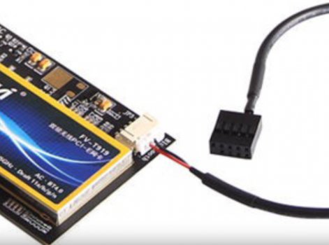
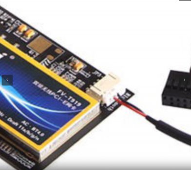
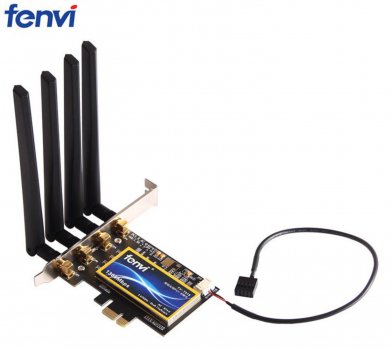
Yep plugs on to supplied included wifi card cable then out back to a USB plug

Soooo... the extension cable arrived a few days ago and I installed it today: from the socket on the card / Fenvi-supplied cable / CRJ extension cable / USB port.... Success!!! My iPhone can see my Mac Pro (nice that it gives me a Mac Pro 2019 icon ;0):

IMG_0889.jpg


And my Mac Pro can receive AirDrops from my iPhone:

Screen Shot 2020-05-26 at 15.50.34.jpg


Problems? I initially connected the USB via a PCie USB 3.0 card... no joy there. When I used the external USB 2.0 sockets that attach directly to the motherboard, all went well.

My Bluetooth mouse and keyboard were initially unresponsive, but I just had to remove them from Bluetooth preferences and re-pair them.

Screen Shot 2020-05-26 at 15.55.49.jpg


I'm still going to go the Airport Card route eventually, though, because I have all the parts necessary, this card was bought for another project and it's occupying a 4x PCIe slot that could be used for something more fitting (the mini PCIe that takes the AirPort card is only 1x).

So, thanks to everyone who offered help and advice... all this on a 2009 (5,1-flashed) Mac Pro: I got there in the end!!!
 
  • Like
Reactions: OkiRun and Ghokun

georgia-ctsv

macrumors member
Jul 17, 2019
34
12
Valdosta, Ga.
Awesome I'm running to of these 1 in a hackintosh and the other in my Mac Pro 3,1. Only issues if you have your cell phone laying on the desk near you magic mouse it'll lag like a mother from the interference from the iPhone.
 
  • Like
Reactions: spetznatz

AlanKeaveney

macrumors newbie
Feb 22, 2017
7
0
Galway, Ireland
Soooo... the extension cable arrived a few days ago and I installed it today: from the socket on the card / Fenvi-supplied cable / CRJ extension cable / USB port.... Success!!! My iPhone can see my Mac Pro (nice that it gives me a Mac Pro 2019 icon ;0):

View attachment 918832

And my Mac Pro can receive AirDrops from my iPhone:

View attachment 918835

Problems? I initially connected the USB via a PCie USB 3.0 card... no joy there. When I used the external USB 2.0 sockets that attach directly to the motherboard, all went well.

My Bluetooth mouse and keyboard were initially unresponsive, but I just had to remove them from Bluetooth preferences and re-pair them.

View attachment 918836

I'm still going to go the Airport Card route eventually, though, because I have all the parts necessary, this card was bought for another project and it's occupying a 4x PCIe slot that could be used for something more fitting (the mini PCIe that takes the AirPort card is only 1x).

So, thanks to everyone who offered help and advice... all this on a 2009 (5,1-flashed) Mac Pro: I got there in the end!!!
Hi,
What extension cable did you end up getting?
I want to get the Fenvi T919 on my 2009 MP (flashed 5,1).

Alan.
 

PianoPro

macrumors 6502a
Sep 4, 2018
511
385
How did you get the USB cable out the rear of the Mac Pro?

Were the 4 antennas a pain with all the other cables on the back of the Mac Pro? (I have 3 monitors and multiple USB 3.0 ports hooked up).
 

jcscore

macrumors newbie
Sep 7, 2020
2
0
Soooo... the extension cable arrived a few days ago and I installed it today: from the socket on the card / Fenvi-supplied cable / CRJ extension cable / USB port.... Success!!! My iPhone can see my Mac Pro (nice that it gives me a Mac Pro 2019 icon ;0):

View attachment 918832

And my Mac Pro can receive AirDrops from my iPhone:

View attachment 918835

Problems? I initially connected the USB via a PCie USB 3.0 card... no joy there. When I used the external USB 2.0 sockets that attach directly to the motherboard, all went well.

My Bluetooth mouse and keyboard were initially unresponsive, but I just had to remove them from Bluetooth preferences and re-pair them.

View attachment 918836

I'm still going to go the Airport Card route eventually, though, because I have all the parts necessary, this card was bought for another project and it's occupying a 4x PCIe slot that could be used for something more fitting (the mini PCIe that takes the AirPort card is only 1x).

So, thanks to everyone who offered help and advice... all this on a 2009 (5,1-flashed) Mac Pro: I got there in the end!!!

Hi, sperznatz. thanks for this great thread. It’s extremely hard to find some clear information about how to install the Fenvi Bluetooth cards for old Mac Pros.

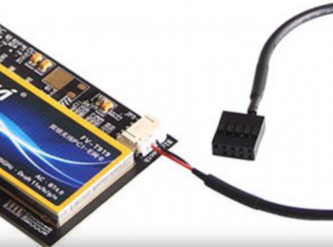
I used the same method of you with Fenvi-T-919 card connected the cable in the box + 9-pin dupon male connector to usb 2.0 male cable.

I plugged the cable into the USB port in the back panel, and it works, but I found I still have trouble.

I could use Bluetooth Low Energy with the Fenvi Wifi card which was my main goal, but I couldn’t connect with my Magic Trackpad anymore.

So I reconnected the AirPort card and attached the antenna cable to it again, now I can connect with the Magic Trackpad, but I can’t use Bluetooth Low Energy. This is a dilemma.

I think I need to find a way how to connect the Bluetooth antenna cable to the new Fenvi Card or buy another cable to connect the Fenvi card with a USB header that is used for the AirPort.
 
Last edited:

spetznatz

macrumors regular
Original poster
Jan 5, 2006
233
35
That's odd, jscore, since I have a Bluetooth mouse and numeric keypad (and keyboard, of course) connecting no problem. The only glitch that I have is that, sometimes, my Mac Pro isn’t seen as an AirDrop target... that requires a restart...?
 

jcscore

macrumors newbie
Sep 7, 2020
2
0
That's odd, jscore, since I have a Bluetooth mouse and numeric keypad (and keyboard, of course) connecting no problem. The only glitch that I have is that, sometimes, my Mac Pro isn’t seen as an AirDrop target... that requires a restart...?


Thanks for reply, spetznatz. Sorry to hear about your inconvenience.

I found that I needed to remove out those old Wi-Fi card and Bluetooth airport card to prevent interference with the new Fenvi Wi-fi card.

Then the original Bluetooth connection for Apple wireless device (I just needed Magic trackpad for Zoom in and out on Logic Pro X) started to work when I deleted "/Library/Preferences/com.apple.BlueTooth.plist," and restart the system.

Now I can use both my Genki Wave Ring wireless MIDI device and Magic Trackpad. I am not sure about the other Apple Bluetooth functions like Airdrop and Handoff, and continuity stuff and other wireless Apple devices like Magic Keyboard, but that’s all I needed.

Thanks so much for this thread again. I hope you can resolve the glitch issue soon.

JC Score
 

Noen-03

macrumors newbie
Nov 19, 2021
3
0
Using the FENVI t919 and the USB extension cable can you access the boot options screen with an Apple Bluetooth keyboard ?

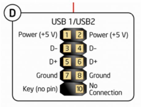
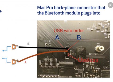
Also on the PCIe Wifi card white connector which pins are D- & D+
Can I just use the D- & D+ connections on the White connector and plug them in Directly into
the Data-in Bluetooth connection on the Logic board ?
this way I will not have to run a USB wire outside the case.
270221C9-8837-4036-AAE6-4A7DB5587C84.jpeg
 

Attachments

  • CF82D568-E48F-4D0B-A9AD-D50ABDDD6B51.jpeg
    CF82D568-E48F-4D0B-A9AD-D50ABDDD6B51.jpeg
    560.8 KB · Views: 153
  • 0EA2C06F-9E5B-4CAB-9265-4D5B1BA9EE94.jpeg
    0EA2C06F-9E5B-4CAB-9265-4D5B1BA9EE94.jpeg
    455.4 KB · Views: 174
Last edited:

Noen-03

macrumors newbie
Nov 19, 2021
3
0

Attachments

  • 0EA2C06F-9E5B-4CAB-9265-4D5B1BA9EE94.jpeg
    0EA2C06F-9E5B-4CAB-9265-4D5B1BA9EE94.jpeg
    455.4 KB · Views: 123

arw

macrumors 65816
Aug 31, 2010
1,238
980
Just compare it with the first image of your previous post.
Look at the big, 10-pin plug and compare the physical location of the yellow (D+) and white (D-) cable with the black and red one‘s of your last post.
 

Noen-03

macrumors newbie
Nov 19, 2021
3
0
Okay yeah, on the FENVI card white connector it looks like the ( BLACK wire is at pin D- ) and
( RED wire is at pin D+ ) according to the wire orientation on the USB header.
On the Photo of the Mac Pro motherboard ( logic board ) it looks like the ( RED wire is at pin D- )
And the ( Black wire is at pin D+ )
 

Attachments

  • 56E4BE96-D431-41EF-AFDB-6C76C95C7062.jpeg
    56E4BE96-D431-41EF-AFDB-6C76C95C7062.jpeg
    170.3 KB · Views: 422
  • 00CD30F1-4591-432D-B3CC-6C745BB6E724.jpeg
    00CD30F1-4591-432D-B3CC-6C745BB6E724.jpeg
    782.3 KB · Views: 360
  • A73442A5-A23F-45AA-A548-348AABEC8136.jpeg
    A73442A5-A23F-45AA-A548-348AABEC8136.jpeg
    264.9 KB · Views: 1,641
  • 995C413B-3268-464A-A87D-9F7A61762DDC.jpeg
    995C413B-3268-464A-A87D-9F7A61762DDC.jpeg
    304.3 KB · Views: 417

AndyDrewSon

macrumors newbie
May 26, 2022
3
0
US
So, I have also bought a FENVI PCI-e Wifi/Bt card (for the sake of having external antennas & mistakenly thinking it would be an easier install). The card I got is similar but not a T919. It is either a Fenvi Model# FV-A436CD or Model# FV-946CD. The model# listed on eBay and the Model#s & images on Fenvi website don't match up accordingly. It is like the T919 in that it's intended for a PC/Hackintosh, using a motherboard 9-digit USB plug for the BT. It is different in that it has 4 wires for BT, instead of only 2.

Link to the WiFi/BT card I bought: eBay Item # 392847805752.
s-l1600h.jpg

I have been trying to figure out how to connect the BT cable, coming off of the PCI-e card, to the old connection for the original BT card. I was planning to cut and splice into the factory wire that attaches the original BT card to the motherboard. But then I found an ifixit thread that identified the appropriate plug that fits the motherboard BT socket. It is a molex connector, 4-pin, 1.5 mm. I ordered it & it arrived today. I actually bought a kit with lots of extras.
Link: Amazon connector kit

However, my card using all 4 wires; not just 2. see pic above. I need to know in what order to hook the other 2 wires?

Some people's cards only have the 2 (red & black) wires coming off of the card. Mine has all 4. I now understand that 2 of those are Data-/+, and I now know where those need to be plugged into the connector, for connecting to the original BT socket on the motherboard. But, what about the other 2 wires?

I need to know how to splice the wires.
The eBay seller of this card told me the pin layout for this cable that came with it:
Red: VCC
White: Data-
Yellow: Data+
Black: GND
Is VCC power supply? and is GND Ground?

I see that the Data- & Data+ will take up the top 2 pins on the original BT motherboard socket. But for the bottom 2 pins, which is which? In what order do I attach The VCC & GND?

Can anyone help me answer this so that I don't mess it up? Does anyone know the full pin layout of the socket?

I know most people have only 2 wires for Data, and they say the bottom 2 pins on the socket don't matter or "they are useless" but, what if my card has all 4? Seems like it needs all 4, since it has them on there, right? The original BT card used all 4 connections on the motherboard, why would the replacement BT card not use all 4 as well?

Thank you to everyone who has commented on this thread so far! You all have provided a lot of valuable information that has gotten me this far. I can't wait to get this upgrade finished and boot it up to see if it works!
I have done a ton of searching and reading on many, many forums and blogs. I cannot find the pin layout of this BT socket anywhere!

Please Help!
 

donzubeck

macrumors member
Feb 12, 2015
31
8
Warren,Mi.USA
So, I have also bought a FENVI PCI-e Wifi/Bt card (for the sake of having external antennas & mistakenly thinking it would be an easier install). The card I got is similar but not a T919. It is either a Fenvi Model# FV-A436CD or Model# FV-946CD. The model# listed on eBay and the Model#s & images on Fenvi website don't match up accordingly. It is like the T919 in that it's intended for a PC/Hackintosh, using a motherboard 9-digit USB plug for the BT. It is different in that it has 4 wires for BT, instead of only 2.

Link to the WiFi/BT card I bought: eBay Item # 392847805752.
View attachment 2009999
I have been trying to figure out how to connect the BT cable, coming off of the PCI-e card, to the old connection for the original BT card. I was planning to cut and splice into the factory wire that attaches the original BT card to the motherboard. But then I found an ifixit thread that identified the appropriate plug that fits the motherboard BT socket. It is a molex connector, 4-pin, 1.5 mm. I ordered it & it arrived today. I actually bought a kit with lots of extras.
Link: Amazon connector kit

However, my card using all 4 wires; not just 2. see pic above. I need to know in what order to hook the other 2 wires?

Some people's cards only have the 2 (red & black) wires coming off of the card. Mine has all 4. I now understand that 2 of those are Data-/+, and I now know where those need to be plugged into the connector, for connecting to the original BT socket on the motherboard. But, what about the other 2 wires?

I need to know how to splice the wires.
The eBay seller of this card told me the pin layout for this cable that came with it:
Red: VCC
White: Data-
Yellow: Data+
Black: GND
Is VCC power supply? and is GND Ground?

I see that the Data- & Data+ will take up the top 2 pins on the original BT motherboard socket. But for the bottom 2 pins, which is which? In what order do I attach The VCC & GND?

Can anyone help me answer this so that I don't mess it up? Does anyone know the full pin layout of the socket?

I know most people have only 2 wires for Data, and they say the bottom 2 pins on the socket don't matter or "they are useless" but, what if my card has all 4? Seems like it needs all 4, since it has them on there, right? The original BT card used all 4 connections on the motherboard, why would the replacement BT card not use all 4 as well?

Thank you to everyone who has commented on this thread so far! You all have provided a lot of valuable information that has gotten me this far. I can't wait to get this upgrade finished and boot it up to see if it works!
I have done a ton of searching and reading on many, many forums and blogs. I cannot find the pin layout of this BT socket anywhere!

Please Help!
I had the same problem as you. I could not get my fenvi 919 to work with any combination of the wires on the logic board. I had to purchase a pci-e card and an adaptor cable and now it works great.

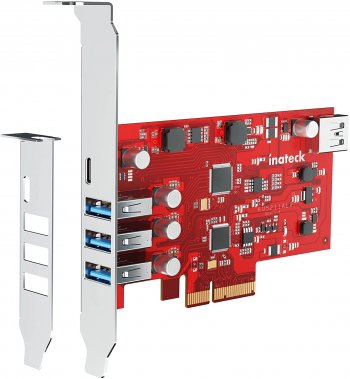
Inateck PCIe USB 3.2 Gen 2 Extension Card with 4 USB-A and 1 USB-C Ports 20 Gbps PCIe 5-Port Card No External Power Supply Required, RedComets U26. (There are two versions of this card, get this one the other one has the 20 Gbps USB port on the inside of the card. I don't think the wifi card needs it.)​

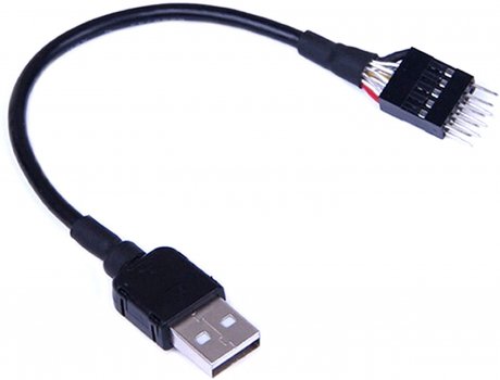
9-Pin USB Motherboard Male Header to Single USB 2.0 Type A Male Cable 7.8inch​


Attachments

  • 61nKT2IZQ0L._AC_SL1500_.jpg
    61nKT2IZQ0L._AC_SL1500_.jpg
    40.6 KB · Views: 144
  • 71gYqB70EpS._AC_SL1500_.jpg
    71gYqB70EpS._AC_SL1500_.jpg
    144.7 KB · Views: 136
Last edited:

startergo

macrumors 603
Sep 20, 2018
5,021
2,283
So, I have also bought a FENVI PCI-e Wifi/Bt card (for the sake of having external antennas & mistakenly thinking it would be an easier install). The card I got is similar but not a T919. It is either a Fenvi Model# FV-A436CD or Model# FV-946CD. The model# listed on eBay and the Model#s & images on Fenvi website don't match up accordingly. It is like the T919 in that it's intended for a PC/Hackintosh, using a motherboard 9-digit USB plug for the BT. It is different in that it has 4 wires for BT, instead of only 2.

Link to the WiFi/BT card I bought: eBay Item # 392847805752.
View attachment 2009999
I have been trying to figure out how to connect the BT cable, coming off of the PCI-e card, to the old connection for the original BT card. I was planning to cut and splice into the factory wire that attaches the original BT card to the motherboard. But then I found an ifixit thread that identified the appropriate plug that fits the motherboard BT socket. It is a molex connector, 4-pin, 1.5 mm. I ordered it & it arrived today. I actually bought a kit with lots of extras.
Link: Amazon connector kit

However, my card using all 4 wires; not just 2. see pic above. I need to know in what order to hook the other 2 wires?

Some people's cards only have the 2 (red & black) wires coming off of the card. Mine has all 4. I now understand that 2 of those are Data-/+, and I now know where those need to be plugged into the connector, for connecting to the original BT socket on the motherboard. But, what about the other 2 wires?

I need to know how to splice the wires.
The eBay seller of this card told me the pin layout for this cable that came with it:
Red: VCC
White: Data-
Yellow: Data+
Black: GND
Is VCC power supply? and is GND Ground?

I see that the Data- & Data+ will take up the top 2 pins on the original BT motherboard socket. But for the bottom 2 pins, which is which? In what order do I attach The VCC & GND?

Can anyone help me answer this so that I don't mess it up? Does anyone know the full pin layout of the socket?

I know most people have only 2 wires for Data, and they say the bottom 2 pins on the socket don't matter or "they are useless" but, what if my card has all 4? Seems like it needs all 4, since it has them on there, right? The original BT card used all 4 connections on the motherboard, why would the replacement BT card not use all 4 as well?

Thank you to everyone who has commented on this thread so far! You all have provided a lot of valuable information that has gotten me this far. I can't wait to get this upgrade finished and boot it up to see if it works!
I have done a ton of searching and reading on many, many forums and blogs. I cannot find the pin layout of this BT socket anywhere!

Please Help!
I used this cable and connected the cable to a USB directly:

And this cable with the connector is for the internal D-. D+ connector:

In stock Walmart:
 
Last edited:

Run75

macrumors newbie
Dec 17, 2019
2
0
France
So, I have also bought a FENVI PCI-e Wifi/Bt card (for the sake of having external antennas & mistakenly thinking it would be an easier install). The card I got is similar but not a T919. It is either a Fenvi Model# FV-A436CD or Model# FV-946CD. The model# listed on eBay and the Model#s & images on Fenvi website don't match up accordingly. It is like the T919 in that it's intended for a PC/Hackintosh, using a motherboard 9-digit USB plug for the BT. It is different in that it has 4 wires for BT, instead of only 2.

Link to the WiFi/BT card I bought: eBay Item # 392847805752.
View attachment 2009999
I have been trying to figure out how to connect the BT cable, coming off of the PCI-e card, to the old connection for the original BT card. I was planning to cut and splice into the factory wire that attaches the original BT card to the motherboard. But then I found an ifixit thread that identified the appropriate plug that fits the motherboard BT socket. It is a molex connector, 4-pin, 1.5 mm. I ordered it & it arrived today. I actually bought a kit with lots of extras.
Link: Amazon connector kit

However, my card using all 4 wires; not just 2. see pic above. I need to know in what order to hook the other 2 wires?

Some people's cards only have the 2 (red & black) wires coming off of the card. Mine has all 4. I now understand that 2 of those are Data-/+, and I now know where those need to be plugged into the connector, for connecting to the original BT socket on the motherboard. But, what about the other 2 wires?

I need to know how to splice the wires.
The eBay seller of this card told me the pin layout for this cable that came with it:
Red: VCC
White: Data-
Yellow: Data+
Black: GND
Is VCC power supply? and is GND Ground?

I see that the Data- & Data+ will take up the top 2 pins on the original BT motherboard socket. But for the bottom 2 pins, which is which? In what order do I attach The VCC & GND?

Can anyone help me answer this so that I don't mess it up? Does anyone know the full pin layout of the socket?

I know most people have only 2 wires for Data, and they say the bottom 2 pins on the socket don't matter or "they are useless" but, what if my card has all 4? Seems like it needs all 4, since it has them on there, right? The original BT card used all 4 connections on the motherboard, why would the replacement BT card not use all 4 as well?

Thank you to everyone who has commented on this thread so far! You all have provided a lot of valuable information that has gotten me this far. I can't wait to get this upgrade finished and boot it up to see if it works!
I have done a ton of searching and reading on many, many forums and blogs. I cannot find the pin layout of this BT socket anywhere!

Please Help!
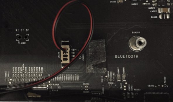
the pinout on Mac 5,1 for the JA120 Bluetooth connector goes like this from top to bottom:

1. D- (This is the top most pin and has a little triangle silkscreen next to it)

2. D+

3. VCC

4. GND (Bottom most pin towards the bottom of the chassis.

So I cut Fenvi cable and simply solder on Mini Micro 1.25mm JST T-1 4-Pin
in order for Mac.
JAGETRADE Mini Micro 1.25mm JST T-1 4-Pin Connector with Wire x 10 Sets

color cable fendi. - color cable on mini micro 1,25 mm JST T-1 on Mac 5,1

VCC red. = Yellow
Data - white = Red
Data+ yellow = Black
GND black = Green


everything works perfectly
 
Last edited:
Register on MacRumors! This sidebar will go away, and you'll see fewer ads.