Become a MacRumors Supporter for $50/year with no ads, ability to filter front page stories, and private forums.
Most of the instruction websites still use the 2011 Mac mini pics from what I have seen so there are very minor differences but that should not cause confusion.

For example there is more emi tape on the 2012 due to it having USB 3.0 (see comment below). And you will notice the fan blades on the 2012 are further apart.

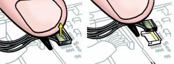
Ifixit as noted does not show the two square EMI (electro magnetic interference) patches because it is the 2011 model. Apple put the patches on the wifi module due to USB 3.0 emi. Whereas the 2011 model being USB 2.0 does not need or have them.

So make sure you keep the two square patches on the wifi module in place when reassembling.

Having said all that, I genrally follow iFixit. They have clear pics. I prefer that to video. I also remove the fan. Too much risk you will rip something off.

FYI, the Apple method is to remove the fan and also dislodge the logic board a few mm (which are the common two disagreed points on the SDD/HDD swap).

Good comments.
I've never heard a piece of black electrician's tape referred to as an electro magnetic interference patch before, but hey, what the hell. Much the same as an "implement for agricultural development".
 
Good comments.
I've never heard a piece of black electrician's tape referred to as an electro magnetic interference patch before, but hey, what the hell. Much the same as an "implement for agricultural development".

Yeah, its confusing. I say all that because I have heard of a few poeple disposing of them because they were not sure what they were.

You should see some thin metalic sheeting under them though? The metalic part almost sperates from the black patch and sticks to the wifi/BT module.

Anyway they are meant to stop the emi noise from the USB ports and cabling affecting (or conflicting with) the wifi and BT signals.

I sort of know all this because I had problems with the USB 3.0 interferring with my Magic Mouse (i.e. BT), so I had to install the more robust OWC emi sheild tape that covers the whole wifi/BT module.

It worked well for me.

Intel wrote a 'famous' white paper on this issue with USB 3.0. The poor consumers who have bought the NT mini stacks are reporting a lot of problems when using them with USB 3.0.

See here if anyone is interested.

http://eshop.macsales.com/item/Other+World+Computing/DIYIMM12BTS/

http://blog.macsales.com/15990-shielding-resolves-usb-3-0-conflict-with-bluetooth

Anyway, I am probably getting off track from the OP's thread. Sorry...
 
Yeah, its confusing. I say all that because I have heard of a few poeple disposing of them because they were not sure what they were.

You should see some thin metalic sheeting under them though? The metalic part almost sperates from the black patch and sticks to the wifi/BT module.

I saw a second strip underneath, but it didn't seem to be metallic at all, merely a thinner shinier strip of sticky plastic tape. I don't use BT but I'll test it with a spare BT mouse. Might be a problem if I get a BT trackpad !
 
1. I bought the Mini from Amazon Germany. They have some of the the cheapest prices around (occasionally Amazon France are better) plus they have free delivery and a 15 day free post return option.

2. The usual place used to be A - nearest to the bottom and the easiest to work with when changing drives. The Mini I modded in 2012 also had the drive in position A. There is some evidence that new Minis come with a single drive in position B ready for a second fusion enabled drive to be in postion A.

3. The right way to deal with changing drives and reinstalling the OS is to clone before replacement. I didn't. To do it properly do the following :
a. Install CarbonCopyCloner on the original in-situ drive.
b. Attach a USB drive (Thumb or Harddrive) of at least 32GB.
c. Use CCC to clone the in-situ drive to the attached USB drive. (Including the Recovery Partition).
d. Check that the USB drive actually boots.
e. Do whatever you intended wrt changing the in-situ drive.
f. Boot from the USB drive.
g. Use Disk Utility to format the new in-situ drive.
h. Clone the USB drive to the new in-situ drive.
i. END

4. I'm following the iFixit guide for the 2012 Mini. Steps 15 and 16 require the logic board and the attached I/O board to be moved slightly to allow easier access to the in-situ drive in position A. I didn't take out the board, merely moved it a bit.

5. I don't have a pic of the WiFi connector (it's reassembled), but if you look at the pic in step 10 of the guide you'll see the connector. In the one I have this is covered by a black plastic strip about 2cm long and 0.5cm wide. Under this is a smaller piece of sticky tape. You need something like a spudger to prise is off delicately. These black strips can be "hinged" for access with the hinge on the LHS by prising them up from the RHS. Plus in my Mini the connector wiring is routed around the connector from top to bottom on the LHS underneath the metal cover. The pic in step 10 shows it routed from bottom to the RHS. (RHS=Right Hand Side; LHS=Left Hand Side)

Uhm ok, that seems to cover up most of my questions... but I have another one (last one, I promise :) ) did you buy a refurbished\used Mac Mini? or a brand new one? (because according to opinio, new Mac Minis come with the HDD in location B) which is, according to the guides, easier to work with when adding (not replacing) a hard drive\SSD.
 
Uhm ok, that seems to cover up most of my questions... but I have another one (last one, I promise :) ) did you buy a refurbished\used Mac Mini? or a brand new one? (because according to opinio, new Mac Minis come with the HDD in location B) which is, according to the guides, easier to work with when adding (not replacing) a hard drive\SSD.

Brand New. That's why I commented that the drive was still in the old position.
 
OK. I ordered the Mac mini today and I should receive it probably this weekend.


I did some more research and found out that many people pried the fan socket\IR socket.

Any tips\precautions I should consider when removing the fan\IR cable?
 
OK. I ordered the Mac mini today and I should receive it probably this weekend.


I did some more research and found out that many people pried the fan socket\IR socket.

Any tips\precautions I should consider when removing the fan\IR cable?

"Pried" = disconnected or broke ?
Just use a thin non-conducting tool and poke underneath the plastic cap. The spudger is best, but apart from that even a long fingernail will do. Reverse the procedure when reassembling with a finger but make sure the socket is realigned. Not much tolerance for misaligning in the Mini.

Pried = broken.

when reversing the procedure, do I slide in the connector or just push it downwards into the socket?

And what do you mean by realigning the socket?
 
Pried = broken.

when reversing the procedure, do I slide in the connector or just push it downwards into the socket?

And what do you mean by realigning the socket?

Just align the connector with the socket and push down. Make sure the sides of the connector are parallel to the sides of the socket and that the connector is sitting on top of the socket before you push. It's not brain surgery but it's precise.

Connectors on the Mini tend to be push down/pry up. Connectors on normal mobos tend to be slide in/pull out.
 
I use to use a sprudger but for the last year I have just pulled up the four wires together and it lifts out.

Apple simply says this in the Tech Guide:

Carefully disconnect
the fan cable from
connector on the
logic board.

On the IR plug. I use long thin tweezers.

I have attached an image from the Tech Guide on this one.

I don't disagree with using a sprudger but you need to be very careful that you are dislodging the male fan plug and not getting the sprudger under the female connector that is soldered to the logic board.
 

Attachments

  • image.jpg
    image.jpg
    114.4 KB · Views: 141
Register on MacRumors! This sidebar will go away, and you'll see fewer ads.