Become a MacRumors Supporter for $50/year with no ads, ability to filter front page stories, and private forums.
Status
The first post of this thread is a WikiPost and can be edited by anyone with the appropiate permissions. Your edits will be public.
@ItsAShaunParty
Haha, that shows the good, the bad, and hints at the ugly in AI... 😉
All wrapped up in non-technical language that gives everything equal weight, so doesn't help decision making. :D
Definitely worth doing (👍) but the sampled data-pool needs more critical assessment (which doesn't happen in a thread like this).

"I think I need to be realistic with myself —"
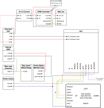
There's a lot to sort out when planning a conversion, and it's a good thing to keep the overall plan simple.
 
  • Like
Reactions: drlamb
First power up sans-speakers was a success! I did not order the HDMI 2.1 (using DP anyways) version from StoneTaskin but can confirm my board came with seemingly updated firmware (I don't see any of the typos mentioned previously etc.). My R1811 has a build date of 09/2025.

One thing came up as I started to wire up the speakers. Which variant of the YLY-2088 would you use and why?


Edit: Removed duplicate pictures already present in thread. See Paul's comments/links below explaining the difference between the two.
 
Last edited:
  • Like
Reactions: PaulD-UK
@drlamb
The Mk2 version is (for iMac use) electronically identical to the original one with ABCD jumper settings.
The values are optimal for 8 ohm speakers, so would work best in an iMac with two pairs of speakers in series... 😉

The blue bass-boost capacitor looks to be 22 microfarad in Mk2, but it is 100 microfarad in Mk1.
It is ONLY NEEDED when you are using the crossover with an additional subwoofer circuit (like in a car)... 😵‍💫

To match the Mk 1 version, the #4 is identical to the Mk1 version with jumpers A,B,C and D connected.
This just uses the Tweeter capacitors, but removes the inductor (and the blue bass-boost capacitor) from the circuit.
YLY-2088iiMatchMk1.jpg


Removing jumper B in Mk1 inserts the inductor, but with iMac 4 ohm speakers that may cut the midrange response.
To match that with Mk2 use this:
YLY-2088iiSettings.jpg


#5 or #6 cannot be matched with the Mk1 version.

Edit: Here's a quick doodle of the circuit:
YLY-2088-Mk2circuit.jpeg
 
Last edited:
  • Love
Reactions: drlamb
I installed the a1419 display in the a1312 case. The difference is 1.5 mm, you need to extend it and the display will fit perfectly, and you can use magnets to have constant access to the insides.
Hi, I have an a1419 LCD for which I have acquired a conversion kit for. I purchased the lcd only (Not the LG LCD, rather, the imac lcd itself with all of apple's added frames and what-nots).
I was trying to figure out a way to either mount it on a custom backplate or some alternative chassis and stumbled upon this thread.

I was wondering if you could share a bit more detail about the process and about how you managed to fit the screen in the a1312 case? how is it held in place? did you use glue of any sort?
Any other pictures to show the build a bit more in detail other than the ones you shared?

Do you (or anyone else for that matter) happen to know the dimensions of the screws on the sides and the bottom (underneath the tape) of the imac's backside?

Thanks in advance, and best regards.
 
@DavArm "...how you managed to fit the screen in the a1312 case? how is it held in place? did you use glue of any sort?"
@gul1ver says he used magnets.
@Borzab used the original iMac adhesive strips, stuck to plywood strips behind the screen glass borders.

"Do you (or anyone else for that matter) happen to know the dimensions of the screws on the sides and the bottom (underneath the tape) of the imac's backside?"

Sorry, that's not clear.
Which iMac? Or do you mean an A1419 iMac's screen panel?
 
  • Like
Reactions: DavArm
Thanks @PaulD-UK for your reply.

I indeed meant the A1419's 27" 5k screen panel. Specifically the - LM270QQ1-SDB2.

I am mostly interested in knowing how does the panel rest inside the a1312's case? The original panel of the a1312's iMac had a frame with magnets that held it in place, but that frame ( I assume) cannot be mounted on the a1419's panel.
I prefer the panel to be in a case over using adhesive strips. I just don't trust It holding the panels weight (and I also want to mount it on an adjustable arm later on).

I was wondering if @gul1ver 'd happen to have more-detailed pictures they could share of the transplant or any tips about the process they went through getting the panel to stay still inside the case? ( Just to be clear and not come-off as an ****** : I'm not expecting you to tear anything down, of course)
Also, did you use the LG model for the conversion, or did you use an iMac panel?

Any bit of information \ suggestions for a case would be of great help and would be very much appreciated🙏
I'd really like to finally put this beautiful display to use.

Thanks in advance, and best regards.
 
Need advice and cable recommendations!

I would like to use the two DisplayPort inputs and the usb-c input on my (yet to arrive) R1811 v4 and need some advice. I was thinking of using 1.5-2' extensions for each of the ports and have the extensions coming out of a modified ram door. I would like to use a usb-c to DisplayPort cable to connect to each of the DisplayPort extensions for use with different Macs as necessary. I would also like to use a usb-c to usb-c cable to connect to the usb-c extension as necessary. It would need to be able to power the display as well as provide charging to a MacBook.

My questions are:

1. Is 1.5-2' long enough for extension cables, or should I use longer ones?
2. What total cable lengths for each controller board port do I need to stay under in order to maintain 5k/60/10 video? I was planning to get 3.3' cables or possibly one 6' cable to be used for the main display cables (which would be added to the 1.5-2' extension cables for total lengths of 5.3' to 8'.
3. Is there a specific type of cable that is DisplayPort to DisplayPort I would need to use if I were to use the display with a PC?
4. I am not planning to use the HDMI ports. Should I still use 1-2 HDMI extension cables through the ram door (for a reason I have not thought of yet)?
5. Does anyone have recommendations on cable brands/types that I should consider for this build?
6. If I use the 5a power supply that comes with the R1811 (from StoneTaskin), can I still use the usb-c port to charge a MacBook Pro? (will it just draw available power, and charge slower?).
 
My preferences snd answers are by no means gospel here <bows to PaulD UK, they holiest>, but my two cents:

1) I would use cables that are a short as possible. This will give you breathing room on the cable you use from the source side.

2) Depends greatly on the quality of the cables. Dont cheap out.

3) Displayport to Displayport cables do exist. Again dont cheap out, may as well get a 2.1-spec cable.

4) Yes

5) Look for certifications and data from tests if possible.

6) Maybe - Defer to someone who has used this board/PSU, I have not.
 
@VegetarianNachos
Using a 24V 5A PSU with a R1811 to power a MBP would only provide 60W at best.
A higher rated PSU could allow higher charging rates.
The PSU would need to be rated to give 100% power for extended periods.

I think the PSUs StoneTaskin supply are probably capable of this, but it remains to be tested in actual use.
Buying a certified PSU, with a data sheet showing how its performance varies under stress or heat, and its MTBF rating, could give a better outcome.

The USB standard does NOT support extension cables.
The reason for this is that to use USB PD charging for a laptop, the cable should have an ID chip embedded in it to identify its safe charging rating.
If you add an extension then this won't have the ID chip, and the extension's rating for safe charging cannot be determined.

In practice, if you make sure the extension comes with packaging displaying a suitable power rating, then this usually isn't a problem...

When buying cables (or extension cables) the important thing it to make sure that the cable is rated for 8K video.
Most cheaper cables are only rated for 4K/60Hz video, and usually these fail when used with a 5K monitor.

Using an (8K) USB-C to DP 1.4 adapter cable works very well.
I've used Cable Matters cables, but any good brand will be fine.

With HDMI it is even more important to get a HDMI 2.1 cable for 5K, because HDMI 2.0 can only manage 4K.
You need a R1811 HDMI 2.1 board for this.

Because the R1811 isn't a Thunderbolt 3 board, it is more tolerant of the cables that work, so in practice, cable length, or extension or adapters isn't a problem.
But the less, length or extensions/adapters, the better.
 
  • Like
Reactions: VegetarianNachos
I now have my R1811 v4 board and have it hooked up and working. Connecting the backlight cable was hard, it was a very tight fit.

What software should I use to fully check out the display to make sure it is at 5k/60/10?

How do I check the board firmware and know that it is the latest version?

Is there a wiring diagram for the crossover boards?
 
Last edited:
@VegetarianNachos "2. What software should I use to fully check out the display to make sure it is at 5k/60/10?"

What version of firmware are you running?
If the OSD is bright blue and yellow then there is a Factory option on the second page of the OSD options that displays this data.

R1811RealTekOSD.jpg


If your OSD is cyan coloured and says V04 (at the top right of the OSD) then, except for the resolution, this information isn't displayed in the OSD, and you have to analyse test images on the monitor screen to determine the node of operation.
Look at How to Test for Chroma Sub-sampling on this page.

You need to download the test image, and open it in preview at 100% size.
The screen should be set to 5K res, not HiDPI, so 5120x2880;
The image is really small at the correct 100% size.

Then take an iPhone photograph to record the look of the image.
If it is not clear then you are not getting full colour information.

R1811OSD.jpg
 
Last edited:
@VegetarianNachos "2. What software should I use to fully check out the display to make sure it is at 5k/60/10?"

What version of firmware are you running?
If the OSD is bright blue and yellow then there is a Factory option on the second page of the OSD options that displays this data.

View attachment 2568621

If your OSD is cyan coloured and says V04 (at the top right of the OSD) then, except for the resolution, this information isn't displayed in the OSD, and you have to analyse test images on the monitor screen to determine the node of operation.
Look at How to Test for Chroma Sub-sampling on this page.

View attachment 2568622
Well that is a bummer. I have the cyan V04 version of firmware. Brightness keys are not working from the keyboard, and I did buy the board directly from StoneTaskin.
 
@VegetarianNachos You need to download Better Display (from GitHub, the free version is enough) to get keyboard control.
It's called DDC/CI and BD has an auto-configure tab to get it working.

BD also allows you to set different colour modes, which helps to test what you are getting on-screen.
 
  • Like
Reactions: VegetarianNachos
@VegetarianNachos You need to download Better Display (from GitHub, the free version is enough) to get keyboard control.
It's called DDC/CI and BD has an auto-configure tab to get it working.

BD also allows you to set different colour modes, which helps to test what you are getting on-screen.
Looks like it is working at 5k/60/10 okay. Now I just need to figure out how to attach the crossover boards. Thanks!
 
  • Like
Reactions: PaulD-UK
I have not heard back from StoneTaskin about the correct way to connect the crossovers to the iMac speakers yet. The wiring colors to the connectors to attach to the speaker connectors are different from others I have found online. I don't want to connect them incorrectly and damage my speakers. Can anyone tell me which way to connect them? On the eBay store for e-qstore-2020 they call the speaker connector side with the two circles "the back", and the other side the front. They have a different set of wire colors than the StoneTaskin ones. Also, is the connection the same for each speaker, and does it matter which crossover connects to which speaker? Thanks!
 

Attachments

  • IMG_1144 copy.jpeg
    IMG_1144 copy.jpeg
    585.9 KB · Views: 15
  • IMG_1145 copy.jpeg
    IMG_1145 copy.jpeg
    266.4 KB · Views: 17
  • IMG_1147 copy.jpeg
    IMG_1147 copy.jpeg
    284.6 KB · Views: 16
@VegetarianNachos You need to start again with the crossover wires. 😉

The plug into the R1811 is inserted correctly.
The four wires from this plug are:
Red - Left speaker +
Black - Left speaker –
Yellow - Right speaker –
Green - Right speaker +

So you have got these connected to the crossover input the wrong way - they need to be reversed.

The jumpers on the crossovers need an additional connection of the Left (4 pin) block - so 1&2 and 3&4 are both connected. The Right (5 pin) block just needs 2&3 connected, which you pic shows.

The outputs of the crossovers are connected correctly to the proper speakers in your pic #1:
In pic #1 the top crossover is Left, lower is Right.

The output wires from each crossover, going to the prongs of the speaker connection (pic #2) are:
Red - Bass speaker +
Black - Bass speaker –
-
-
Blue - Hi speaker +
White - Hi speaker –

In your pic #3 speaker connection, the connections from Top to Bottom (as you are showing it) are:

Hi speaker –
Hi speaker +
-
-
Bass speaker –
Bass speaker +

So you need to swap around either prongs OR speaker connection (only one) to plug them in correctly. :)

This post has the speaker connections identified correctly:
 
Last edited:
  • Like
Reactions: VegetarianNachos
@VegetarianNachos You need to start again with the crossover wires. 😉

The plug into the R1811 is inserted correctly.
The four wires from this plug are:
Red - Left speaker +
Black - Left speaker –
Yellow - Right speaker –
Green - Right speaker +

So you have got these connected to the crossover input the wrong way - they need to be reversed.

The jumpers on the crossovers need an additional connection of the Left (4 pin) block - so 1&2 and 3&4 are both connected. The Right (5 pin) block just needs 2&3 connected, which you pic shows.

The outputs of the crossovers are connected correctly to the proper speakers in your pic #1:
In pic #1 the top crossover is Left, lower is Right.

The output wires from each crossover, going to the prongs of the speaker connection (pic #2) are:
Red - Bass speaker +
Black - Bass speaker –
-
-
Blue - Hi speaker +
White - Hi speaker –

In your pic #3 speaker connection, the connections from Top to Bottom (as you are showing it) are:

Hi speaker –
Hi speaker +
-
-
Bass speaker –
Bass speaker +

So you need to swap around either prongs OR speaker connection (only one) to plug them in correctly. :)

This post has the speaker connections identified correctly:
Oh wow. How do these changes look now?
 

Attachments

  • IMG_1148 copy.jpeg
    IMG_1148 copy.jpeg
    574.7 KB · Views: 18
  • IMG_1149 copy.jpeg
    IMG_1149 copy.jpeg
    303.4 KB · Views: 18
  • Like
Reactions: drlamb and PaulD-UK
Thank you everyone here for detailing your experiences. I am currently sourcing parts for a relatively simple mid-2015 iMac conversion. I'm going with a R9A18 using 2 DisplayPort and will be keeping the speakers, inline wiring caps and coils for crossover.

If anyone is working on a 2DP setup, I wanted to let you know that OWC has their Thunderbolt to Dual DisplayPort Adapter on sale for $39.99 (US) with free standard shipping. Normally sells for twice that amount.
 
Last edited:
  • Like
Reactions: PaulD-UK
Register on MacRumors! This sidebar will go away, and you'll see fewer ads.