Hi all,
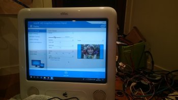
Just a note to say I've been working on getting an eMac CRT going as well, and have had success with the arduino sketch by rockyhill. I've also figured out what some of the i2c commands do (eg. adjusting brightness/geometry), so I'll update the wikibooks at
https://en.wikibooks.org/w/index.php?title=How_to_modify_an_eMac_to_use_as_an_external_monitor
The main outstanding issue I have is that because of the fixed horizontal scan rate of the CRT (presumably the refresh rate of the BIOS/UEFI screen is wrong?) I can't get into the BIOS of the PC (Lenovo ThinkCentre M93 Tiny) I'm using to set up the wireless card; unfortunately I don't have another monitor to do it. I will try using the EDID simulator sketch (
https://github.com/qbancoffee/edid_simulator) at some point to see if that forces the PC to pick a suitable refresh rate, but my current cheap VGA cable doesn't have the correct i2c pins on.
Below is an extract of the modified code from rockyhill with the function and range of the different commands, incase anyone is interested before the wikibooks gets updated. Some of them seem to have two ranges of 128 levels which do the same thing rather than one range of 256, and some cause the screen to go blank when they're out of range:
writeToIvad(70, 0x01 , 0xAE); //backlight green, range 00-FF
writeToIvad(70, 0x02 , 0xAA); //backlight blue, range 00-FF
writeToIvad(70, 0x03 , value[8]); //backlight red, range 00-FF
writeToIvad(70, 0x04 , 0xBF); //top width/pinch, range 00-7F & 80-FF
writeToIvad(70, 0x05 , 0xBC); //top lean 00-7F & 80-FF
writeToIvad(70, 0x06 , 0x3B); //bottom lean 00-7F & 80-FF
writeToIvad(70, 0x07, value[6]); //horizontal position, 80-FF
writeToIvad(70, 0x08 , value[3]); //vertical size, 80-FF
writeToIvad(70, 0x09 , value[4]); //vertical position, 00-7F, 80-FF
writeToIvad(70, 0x0A , 0x96); //some kind of image adjustment, like a sphere in the centre of screen, 00-FF
writeToIvad(70, 0x0B , value[7]); //keystone, 00-FF
writeToIvad(70, 0x0C , value[2]); //pincushion, 00-FF
writeToIvad(70, 0x0D , value[5]); //horizontal size, 00-7F, 80-FF
writeToIvad(70, 0x0E , 0xC5); //top and bottom pull left & right, 80-FF
writeToIvad(70, 0x0F , value[9]); //paralellogram, 00-FF
writeToIvad(70, 0x10 , 0x8F); //some kind of contrast, possibly gamma? 80-BF & C8-FF
writeToIvad(70, 0x11 , value[0]); //brightness, 00-3F, 40-7F
writeToIvad(70, 0x12 , 0x46); //some kind of horizontal size, 00-FF
writeToIvad(70, 0x14 , 0x37); //some kind of vertical size, 00-7F, 80-FF
writeToIvad(70, 0x15 , 0x43); //bottom width/pinch, 00-7F & 80-FF
writeToIvad(76, 0x00 , 0xD4); //backlight/colour temp blue->red, 00-FF
writeToIvad(76, 0x01 , 0xCE); //backlight/colour temp yellow->blue, 00-FF
writeToIvad(76, 0x02 , 0xCE); //backlight/colour temp magneta->blue/green, 00-FF
writeToIvad(76, 0x03 , 0x9D); //rotation, 00-FF
writeToIvad(70, 0x00 , value[1]); //contrast, 80-FF
Thanks to patriciooholegu and rockyhill for the previous work!
Jamie
[doublepost=1515274222][/doublepost]Also for those working on iMacs in need of a logic analyser, I had some success with
https://github.com/rricharz/i2c-sniffer-100kBaud-Arduino-Mega running on an arduino mega. I originally wanted an iMac rather than an eMac but I wasn't going to pay £100 for one to rip apart...

![IMG_20170818_202623[304].jpg](/data/attachments/628/628592-a9cb7b77c135bd65ef8c42d8d8dbeee2.jpg)