Become a MacRumors Supporter for $50/year with no ads, ability to filter front page stories, and private forums.

WhatDoYouGuysWannaDo

macrumors newbie
Oct 7, 2015
20
13
Oh wow!

This is Stephen Ferris, the guy who did the mod with the grape tray loading iMac! I’m really excited about this as I also have a lime green iMac DV that I’d like to do. I started trying at one point but realized it was a lot more complex than the tray loader, so I gave up.

Sadly, my trayloader eventually stopped working because the power supply wore out. They only have 80 watts, and are known to wear out even with the original G3 logic boards. From what I understand, the slot loaders have 150 watts, which should be enough for most itx boards.

One thing I like about going the hackintosh route is that you can enter the original serial number of the iMac, and it will recognize it as an iMac G3 in About This Mac. On my main hackintosh in a digital audio G4 case, I even called Apple and gave them the serial number so I could use Messages and what not. I told them I “upgraded” the G4 to run Yosemite, and they were really impressed, lol.
 

sparpet

macrumors newbie
Aug 23, 2017
4
2
I leave here the log from the logic analyzer in case anyone wants to code it

EDIT: Should i start another thread so we can get more exposure and hopefully someone knowledgeable could help?
 

Attachments

  • imac_data.txt
    6.4 KB · Views: 547
Last edited:

jamie-g

macrumors newbie
Jan 6, 2018
2
2
Hi all,

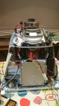
Just for those who are interested, I did manage to squeeze the thinkcentre tiny motherboard (mini-ITX I think) and it's external PSU inside the emac along with a 5.25" DVD drive. I had to cut out some of the internal cage which held the original logic board, but it did go in! I had to change the DVD drive to a SATA drive as I couldn't get a converter to work with the original PATA drive. I also managed to fit the arduino and an audio amplifier inside, along with two DC-DC converters which change the ~20v of the analog board to +12v & +5v. The arduino powers on the motherboard, along with the DVD drive, audio amp and original fan when you switch it on with the eMac power button. I haven't wired up the blue LED, but it would be straightforward to do so.

The outstanding issues are that the audio amp is quite noisy, and also the image on the CRT wobbles about when you use the DVD drive. It didn't do that initially, so I'm not sure if I've broken something along the way. Presumably this could be solved by using an external 12v/5v PSU - I do have one, but there's no way it will fit inside the emac case, so I haven't used it so far. The other issue is that the CRT doesn't power down when the PC is switched off (presumably the logic board would have powered it down - see http://www.lbodnar.dsl.pipex.com/eServer/) so it still uses power and generates heat unless you switch it off at the mains.

I haven't put macOS on it, but other people have been successful with the same motherboard (https://www.tonymacx86.com/threads/success-yosemite-10-10-0-on-lenovo-m93p.147139/) so it's presumably possible. You would need an external monitor to do the install, because as previously noted the eMac CRT refresh rate doesn't match with what comes out of the new motherboard.

Jamie
 

Attachments

  • DSC_1674.JPG
    DSC_1674.JPG
    1.1 MB · Views: 609
  • Like
Reactions: txgraeme

stratosmacker

macrumors newbie
May 25, 2018
1
0
Hi I feel bad that I've not kept up with this thread! The iMac has been in storage since February 2016 and still is, but it was working fine as a monitor, with the power button/ LED and reset buttons all doing their thing. My plan was (still is) to stuff a tiny PC in there, along with a small audio amp to drive the speakers.

Approach was much the same as yours, rockyhill, using an Arduino to talk to the IVAD board over I2C simulating the commands that would usually come from or via the iMac's openfirmware. Also mostly figured out the CRT geometry / alignment commands.

I hadn't bothered to try an emulate the EDID if requested from the computer, as it seemed to work okay without. The iMac's IVAD does hold EDID data, but if I remember rightly it's at a funny address and partially nonsense.

The Arduino sketches I came up with were pretty rough, and I was going to look at using interrupts to make it all a bit less messy. Annoyingly all the I2C info and Arduino sketched etc are also in storage on my 'project' PC.

Bare with me til March/ early April and I'll have access to it all again and time to look at it all!

Cablemunkey , did you ever get around to finding your old sketches etc? I'd be happy to help, I'm picking up a slot loader tomorrow to try to retromod it.
 

YellowBirdAZ

macrumors newbie
Sep 30, 2019
1
0
I know this thread is 84 years old, but have there been any updates yet?

Are you still working on this? Any leads?

I have been working on this same project (the eMac version). I can get the monitor to power up but the screen remains dark. I am not sure if something is wrong with my Arduino I2C power-on signal (it requires a specific sequence, which I got from a guy who posted his project on YouTube as "Rocky Hill") or if I'm failing to send one of the specific video signals the Apple monitor requires. I thought I had 1280x960 @ 72 Hz going out but maybe not.

Also I'm unclear on the sequence of events required... obviously the CRT has to have power to the logic board first. Then does it matter whether a video signal is received before or after the I2C signal? Or can they come simultaneously?

This turned out to be a MASSIVE headache.
 

FrankClochard

macrumors newbie
Jan 8, 2020
3
1
I leave here the log from the logic analyzer in case anyone wants to code it

EDIT: Should i start another thread so we can get more exposure and hopefully someone knowledgeable could help?
Another thread could be useful, we need someone that knows how to use your readings.
 
Last edited:

rockyhill

macrumors regular
Dec 24, 2016
214
67
Miami Fl, United States
I'm going to try and send video to the crt tomorrow but before I do that I was wondering if anyone
has or can get the EDID for this display. Does anyone have it? or can get it?
This would make things go a little faster. If not I'll try and generate it.

Fingers crossed........
 
  • Like
Reactions: MisterKeeks

FrankClochard

macrumors newbie
Jan 8, 2020
3
1
I'm going to try and send video to the crt tomorrow but before I do that I was wondering if anyone
has or can get the EDID for this display. Does anyone have it? or can get it?
This would make things go a little faster. If not I'll try and generate it.

Fingers crossed........
I have no clue how to get the edid, but could it be possible to just ground DDC0 and DDC2 to signal a coloured 1024x768 monitor?
 

rockyhill

macrumors regular
Dec 24, 2016
214
67
Miami Fl, United States
Looking pretty goo in full screen.....

[automerge]1580000113[/automerge]
I just saw the video on on youtube and the picture seems to have a purple hue. This is probably due to the
processing after uploading because it does not look like that in person. There is a slight tinge but not to the
degree seen in the video.
 

rockyhill

macrumors regular
Dec 24, 2016
214
67
Miami Fl, United States
Hi all,

Just a note to say I've been working on getting an eMac CRT going as well, and have had success with the arduino sketch by rockyhill. I've also figured out what some of the i2c commands do (eg. adjusting brightness/geometry), so I'll update the wikibooks at https://en.wikibooks.org/w/index.php?title=How_to_modify_an_eMac_to_use_as_an_external_monitor

The main outstanding issue I have is that because of the fixed horizontal scan rate of the CRT (presumably the refresh rate of the BIOS/UEFI screen is wrong?) I can't get into the BIOS of the PC (Lenovo ThinkCentre M93 Tiny) I'm using to set up the wireless card; unfortunately I don't have another monitor to do it. I will try using the EDID simulator sketch (https://github.com/qbancoffee/edid_simulator) at some point to see if that forces the PC to pick a suitable refresh rate, but my current cheap VGA cable doesn't have the correct i2c pins on.

Below is an extract of the modified code from rockyhill with the function and range of the different commands, incase anyone is interested before the wikibooks gets updated. Some of them seem to have two ranges of 128 levels which do the same thing rather than one range of 256, and some cause the screen to go blank when they're out of range:

writeToIvad(70, 0x01 , 0xAE); //backlight green, range 00-FF
writeToIvad(70, 0x02 , 0xAA); //backlight blue, range 00-FF
writeToIvad(70, 0x03 , value[8]); //backlight red, range 00-FF
writeToIvad(70, 0x04 , 0xBF); //top width/pinch, range 00-7F & 80-FF
writeToIvad(70, 0x05 , 0xBC); //top lean 00-7F & 80-FF
writeToIvad(70, 0x06 , 0x3B); //bottom lean 00-7F & 80-FF
writeToIvad(70, 0x07, value[6]); //horizontal position, 80-FF
writeToIvad(70, 0x08 , value[3]); //vertical size, 80-FF
writeToIvad(70, 0x09 , value[4]); //vertical position, 00-7F, 80-FF
writeToIvad(70, 0x0A , 0x96); //some kind of image adjustment, like a sphere in the centre of screen, 00-FF
writeToIvad(70, 0x0B , value[7]); //keystone, 00-FF
writeToIvad(70, 0x0C , value[2]); //pincushion, 00-FF
writeToIvad(70, 0x0D , value[5]); //horizontal size, 00-7F, 80-FF
writeToIvad(70, 0x0E , 0xC5); //top and bottom pull left & right, 80-FF
writeToIvad(70, 0x0F , value[9]); //paralellogram, 00-FF
writeToIvad(70, 0x10 , 0x8F); //some kind of contrast, possibly gamma? 80-BF & C8-FF
writeToIvad(70, 0x11 , value[0]); //brightness, 00-3F, 40-7F
writeToIvad(70, 0x12 , 0x46); //some kind of horizontal size, 00-FF
writeToIvad(70, 0x14 , 0x37); //some kind of vertical size, 00-7F, 80-FF
writeToIvad(70, 0x15 , 0x43); //bottom width/pinch, 00-7F & 80-FF

writeToIvad(76, 0x00 , 0xD4); //backlight/colour temp blue->red, 00-FF
writeToIvad(76, 0x01 , 0xCE); //backlight/colour temp yellow->blue, 00-FF
writeToIvad(76, 0x02 , 0xCE); //backlight/colour temp magneta->blue/green, 00-FF
writeToIvad(76, 0x03 , 0x9D); //rotation, 00-FF

writeToIvad(70, 0x00 , value[1]); //contrast, 80-FF

Thanks to patriciooholegu and rockyhill for the previous work!

Jamie
[doublepost=1515274222][/doublepost]Also for those working on iMacs in need of a logic analyser, I had some success with https://github.com/rricharz/i2c-sniffer-100kBaud-Arduino-Mega running on an arduino mega. I originally wanted an iMac rather than an eMac but I wasn't going to pay £100 for one to rip apart...


Hi Jamie,
I know it's been a while but I was able to use what you wrote up in the wiki to tweak the picture
for the iMac G3. I ave a nice looking picture now.

Thanks!
 
  • Like
Reactions: LightBulbFun

rockyhill

macrumors regular
Dec 24, 2016
214
67
Miami Fl, United States
Finally got it working without the logic board! !!!

I'll document what I did as soon as I can and then I think my next project will be a
printed circuit board that just plugs into the IVAD connector and turns and serve as
the initialization board and the will spit out the EDID to any computer that
is plugged into. Here's the video.

 
  • Like
Reactions: LightBulbFun

rockyhill

macrumors regular
Dec 24, 2016
214
67
Miami Fl, United States
Congratulations!
You did it, finished the project
How did the CRT start without the arduino?

I connected the I2C lines for the IVAD board to the I2C lines on the raspberry pi GPIO header.
I then ported the arduino sketch to a python script and sent the initialization code that way.

the python script is executed when ".bashrc" for the "pi" is executed after login.
It's rudimentary and only for a single user but we can polish it later.
[automerge]1580516975[/automerge]
I'm not quite finished either , I plan on doing some more...............
 

rockyhill

macrumors regular
Dec 24, 2016
214
67
Miami Fl, United States
I'm starting to put together some diagrams and pin-outs to reference.
This is based on stuff I've seen online and on measurements and tests I've done.

Unfortunately my iMac does not have an audio jack board. Somehow it was ripped out so I could not
buzz it out to the audio connectors, only to the wires that are where the board should be.
I've included the wire colors in the drawing I made to see if someone with an audio jack
board can match them up.
I've also included the python script to initialize the IVAD board straight from the raspberry pi.
the Below is the link.

https://github.com/qbancoffee/imac_g3_ivad_board_init
 

elvisa

macrumors newbie
Feb 1, 2020
19
4
Many thanks everyone working on this, and especially Rocky for your recent progress (I'm "Dan" who has been commenting on your YouTube videos).

I've prepped my RPi ready to try this out with the i2c pins and software enabled and the relevant Python libraries installed. I'll wait for your pinouts, but I've got a pretty clean Bondi Blue iMac G3 333MHz and will be attempting to connect my Pi direct to the iMac's DB15 cable, and pull 5V for my Pi from the ATX cable (the logic board has been completely removed, but I confirmed the monitor powered on while it was still in there).

I'm struggling to find documentation that makes sense (due to my own ineptitude). I *think* I need pins 7 and 10 from the DE15 cable for the i2c SDA and SLC.

The other thing I'm wondering is do I need to bridge the ATX power PS_ON and ground pins like I would on a PC power supply?

Happy to wait on the documentation you're going to write up, Rocky.

My front panel header on my iMac is all in tact, so once I get video up and running I can try and get audio wired up as well.

Pretty excited to breathe some life back into this old thing.
 

rockyhill

macrumors regular
Dec 24, 2016
214
67
Miami Fl, United States
Many thanks everyone working on this, and especially Rocky for your recent progress (I'm "Dan" who has been commenting on your YouTube videos).

I've prepped my RPi ready to try this out with the i2c pins and software enabled and the relevant Python libraries installed. I'll wait for your pinouts, but I've got a pretty clean Bondi Blue iMac G3 333MHz and will be attempting to connect my Pi direct to the iMac's DB15 cable, and pull 5V for my Pi from the ATX cable (the logic board has been completely removed, but I confirmed the monitor powered on while it was still in there).

I'm struggling to find documentation that makes sense (due to my own ineptitude). I *think* I need pins 7 and 10 from the DE15 cable for the i2c SDA and SLC.

The other thing I'm wondering is do I need to bridge the ATX power PS_ON and ground pins like I would on a PC power supply?

Happy to wait on the documentation you're going to write up, Rocky.

My front panel header on my iMac is all in tact, so once I get video up and running I can try and get audio wired up as well.

Pretty excited to breathe some life back into this old thing.

Hey Dan,

No problem, this is fun!

Just added a diagram based on how I wired the a VGA cable to my iMac CRT

https://github.com/qbancoffee/imac_g3_ivad_board_init/blob/master/README.md

good luck!
 
  • Like
Reactions: AphoticD

rockyhill

macrumors regular
Dec 24, 2016
214
67
Miami Fl, United States
I've made several wiring diagrams and wrote up instructions to get the CRT working with a raspberry pi.
I recreated the steps as best I could so hopefully I didn't miss any.

https://github.com/qbancoffee/imac_g3_ivad_board_init

Please fork this repo and make your own edits and do pull requests so I can merge your changes.


I'll add steps for the arduino sometime this week.
Once there is enough info in this repo I'll use it as a guide start putting together a schematic and PCB(s) in KiCad.

I think I can make a PCB(s) that can plug into the chassis connectors to make the process of modding the iMac cleaner
and faster. This way we can use the existing power button, the mic, the headphone jack and the speakers .

Good luck and happy modding to whoever does this.
 
  • Like
Reactions: AphoticD

rockyhill

macrumors regular
Dec 24, 2016
214
67
Miami Fl, United States
Many thanks everyone working on this, and especially Rocky for your recent progress (I'm "Dan" who has been commenting on your YouTube videos).

I've prepped my RPi ready to try this out with the i2c pins and software enabled and the relevant Python libraries installed. I'll wait for your pinouts, but I've got a pretty clean Bondi Blue iMac G3 333MHz and will be attempting to connect my Pi direct to the iMac's DB15 cable, and pull 5V for my Pi from the ATX cable (the logic board has been completely removed, but I confirmed the monitor powered on while it was still in there).

I'm struggling to find documentation that makes sense (due to my own ineptitude). I *think* I need pins 7 and 10 from the DE15 cable for the i2c SDA and SLC.

The other thing I'm wondering is do I need to bridge the ATX power PS_ON and ground pins like I would on a PC power supply?

Happy to wait on the documentation you're going to write up, Rocky.

My front panel header on my iMac is all in tact, so once I get video up and running I can try and get audio wired up as well.

Pretty excited to breathe some life back into this old thing.

Hey Dan

It is very much a struggle to find coherent documentation for all of this so I too am feeling a bit lost....
The VGA cable uses pins 12 & 15 as SDA and SCL respectively and you should be able to use any
of the grounds on the cable to hook into the pi

To turn the CRT analog board on, you only need to short pins 10 and 6 on what I'm calling J20 for about 2 seconds.
To turn it off you need to short pin 10 to ground. Use the chassis or pin 3. Be careful not to short pin 10 to
a nearby 50V pin. I think that might kill the IVAD board.

Keep in mind that I'm calling these pins 10 and 6 and 3 relative what I wrote up and that someone else might have
a different numbering scheme......

J20 puts out 50v on several of the pins and I think this is what was stepped down and used to power the logic board.
Eventually I think with the right voltage regulator or buck converter or something, we could power the pi/arduino or
dvd tray ect.. from here.


Here is a link to the wiring diagram
.
vga_adapter.png


Here are the on/off pins

crt_power_on_and_off.png
 
Last edited:
Register on MacRumors! This sidebar will go away, and you'll see fewer ads.