Become a MacRumors Supporter for $50/year with no ads, ability to filter front page stories, and private forums.

paardenkapper

macrumors regular
Original poster
Apr 8, 2023
194
121
Germany
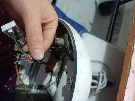
Hi there. Since my iMac is probably beyond repair I thought about building a casemod and using the 15'' display as an external one for my macbook or so.

I have come across many threads in this forum as well as this video:
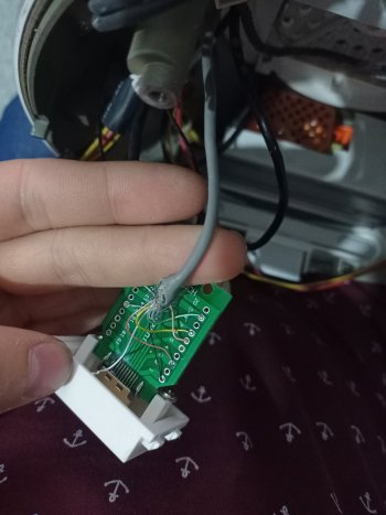
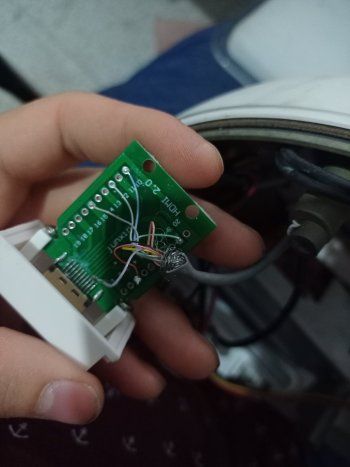
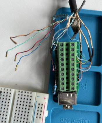
But I am still not 100% sure about this. As far as I understand this you just have to splice the video cable into separate lines and put it into an HDMI breakout board.

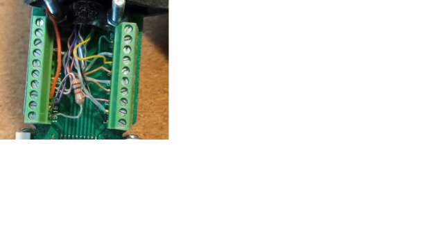
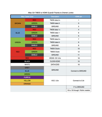
I have a screenshot from the video above which makes me wonder:

1. Where does that orange cable come from - it should be GND?
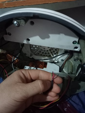
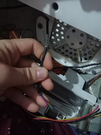
2. Unfortunately he does not show the display power connector (inverter) but says he uses a molex connector from an ATX power supply yet as far as I know this delivers 12V and 5V and not 3.3V

Has anyone done this before and can show me the power connection? If I carry this out I'd like to buy a suitable power supply as my PSU is broken.

Thank you!
 

Attachments

  • hdmi pins.jpg
    hdmi pins.jpg
    72.3 KB · Views: 288
  • Like
Reactions: AKDO

paardenkapper

macrumors regular
Original poster
Apr 8, 2023
194
121
Germany
Well, as I did not find a suitable PSU I decided to go forward with this project.
I bought an HDMI breakout plug and I'm pretty sure that I got the connections of DATA right.

The thing is I am hesitant with the power connections. Could someone please explain to me how I connect the wires seen in the pictures? I know there are plenty of guides and whatnot but they do not help me right now.

As a power source I have a Molex PSU used for external hard drives and I guess this should be sufficient?

IMG_2575.jpg


IMG_2574.jpg
 
  • Like
Reactions: AKDO

paardenkapper

macrumors regular
Original poster
Apr 8, 2023
194
121
Germany
It's kind of talking to myself but I have now proceeded with connecting the inverter to power.
12V / 5V and 5V through 1K resistor - the screen does light up grey.

I connected the rest of the connectors in the way I understood it.

The display is seen on my MacBook as 1024x768 display but there is no picture. What am I missing here?
 
  • Like
Reactions: AKDO

Needleroozer

macrumors regular
Mar 29, 2013
137
197
It's kind of talking to myself but I have now proceeded with connecting the inverter to power.
12V / 5V and 5V through 1K resistor - the screen does light up grey.

I connected the rest of the connectors in the way I understood it.

The display is seen on my MacBook as 1024x768 display but there is no picture. What am I missing here?

I haven't done a 15" conversion myself, but this post seems to have the same problem as you did - possibly you need to supply 3.3V rather than 5V to the display? If you have some rectifier diodes you can put in series with the 5V line, two should get you down to the 3.6V range or so, which ought to be pretty close to safe.


paardenkapper

macrumors regular
Original poster
Apr 8, 2023
194
121
Germany
Thank you very much for helping out, I read that many threads it must have confused me to the state I'm in.
And I read that I need 3.3v instead of 5v - yet the inverter does need 5v at some point - right?

1) Is it right, that I have 2 wires left from the inverter cable which are not used (purple + translucent)?
2) Do I need to add 3.3v to Pin 18?
3) I am not sure about the green inverter wire...?

So here is my connection right now.

HDMI PINConnects to
1DATA 2
2DATA 2
3DATA 2
4DATA 1
5DATA 1
6DATA 1
7DATA 0
8DATA 0
9DATA 0
10DATA CLOCK
11DATA CLOCK
12DATA CLOCK
13-
14-
15 EDID CLOCK
16EDID DATA
17GND
18Purple wire + 1K Resistor
191K Resistor
GND-

Inverter WireConnects to
Red5V
Green5V with a 1K resistor added
BlackGND
Blue12V
 
  • Like
Reactions: AKDO

paardenkapper

macrumors regular
Original poster
Apr 8, 2023
194
121
Germany
I have put everything together quite orderly and will upload some photos. Maybe someone can help me out some more:

1) How could I implement some sort of power button - my psu does not have one - would it be okay if I add one to the ground connection (-) ?
2) I noticed that the voltage drops to around 10.3 volts - it still seems to run fine but it's probably not great in the long run?
3) How can I make the status LED work again?

Thanks again.
 
  • Like
Reactions: AKDO

Needleroozer

macrumors regular
Mar 29, 2013
137
197
I have put everything together quite orderly and will upload some photos. Maybe someone can help me out some more:

1) How could I implement some sort of power button - my psu does not have one - would it be okay if I add one to the ground connection (-) ?

Putting a switch in series with the ground line on the power supply would work as long as your grounds are properly isolated (i.e. the chassis does not provide an alternate path the ground for your DC power supply).

I would probably try to hook up some sort of relay board that accepts a momentary switch input so that you could reuse the original power switch button and location (assuming it still works - that was the start of your whole adventure as I recall).

2) I noticed that the voltage drops to around 10.3 volts - it still seems to run fine but it's probably not great in the long run?

Dropping 2V under load like that is a bit concerning; I would probably try to upgrade to a higher-power supply. Everything in the display is probably running off of a switching regulator anyway (and so will be auto-adjusting to make do), but that’s probably a bit outside of those components’ design range.

3) How can I make the status LED work again?

Thanks again.

I took a look at the schematics, and I think that the status LED runs to pins 22 and 23 of the 26-pin J13 “Kitchen Sink” connector that also carries the mic line down from the display. If it’s like the 17” iMac G4, it’ll be pink and green wires.
47DD7D82-6963-4DB6-AA1C-7EF8A7CD009D.jpeg
From that wiring, you should be able to throw 5V on pin 22 and GND on pin 23 to light up the LED, but I’d probably put a 200Ω (ish) resistor in series with that LED at first just to be safe.

EDIT: It may also be a good idea to test those lines with a multimeter in diode test mode since that is a low-current mode that shouldn’t be able to break anything. On the other hand, that may not be enough current to make the LED light up very visibly through the plastic bezel.
 

Attachments

  • 820-1398.pdf
    1.3 MB · Views: 93
Last edited:

paardenkapper

macrumors regular
Original poster
Apr 8, 2023
194
121
Germany
You're right. I still have the old mainboard from the G4 and as soon as I stumble upon a working unit I will test the board and eventually resell it to give it a second life. I think making this unit a display was not the worst to happen.

I am using a cheapo power supply for external harddrives I had in a box. If I ever come across a working yet small ATX psu I'll give it a try. This might just work for now.

Thanks for the schematics - I will take a closer look this weekend and measure the voltages carefully.

Another thing to consider would be reusing the old speaker from the iMac - I wonder how that could be achieved.

I will keep you posted on any success.
 
  • Like
Reactions: AKDO

Needleroozer

macrumors regular
Mar 29, 2013
137
197
You're right. I still have the old mainboard from the G4 and as soon as I stumble upon a working unit I will test the board and eventually resell it to give it a second life. I think making this unit a display was not the worst to happen.

I am using a cheapo power supply for external harddrives I had in a box. If I ever come across a working yet small ATX psu I'll give it a try. This might just work for now.

Thanks for the schematics - I will take a closer look this weekend and measure the voltages carefully.

Another thing to consider would be reusing the old speaker from the iMac - I wonder how that could be achieved.

I will keep you posted on any success.
The speaker is just a normal 8Ω speaker, I believe. You could just solder it directly to a 3.5mm jack and drive it like that, or you might be able to get an HDMI audio extractor and a small amp like an LM386 to tunnel the audio over HDMI.
The question with that would be if the EDID of the iMac display allows for audio-over-HDMI (unlikely) or if an extractor box like the one below would be able to override that portion of the EDID to allow for audio output (possible but unknown).
 

AKDO

macrumors newbie
Nov 8, 2023
2
0
hello, great job I'm happy you pulled it, I'm struggling here, I don't know which cable to use there's a gray cable with a black cable attached to it and that black cable has 4 wires (brown, brownish red, blue, and green) and each wire has two small wires (blue and red), I hope you can clear things up for me I really appreciate it.
 

Attachments

  • IMG20231108230043.jpg
    IMG20231108230043.jpg
    309.8 KB · Views: 49
  • IMG20231108230142.jpg
    IMG20231108230142.jpg
    325.9 KB · Views: 53
  • IMG20231108230119.jpg
    IMG20231108230119.jpg
    315.6 KB · Views: 48
  • IMG20231108230052.jpg
    IMG20231108230052.jpg
    335.3 KB · Views: 48
  • IMG20231108230034.jpg
    IMG20231108230034.jpg
    268.5 KB · Views: 46

paardenkapper

macrumors regular
Original poster
Apr 8, 2023
194
121
Germany
hello, great job I'm happy you pulled it, I'm struggling here, I don't know which cable to use there's a gray cable with a black cable attached to it and that black cable has 4 wires (brown, brownish red, blue, and green) and each wire has two small wires (blue and red), I hope you can clear things up for me I really appreciate it.

Hey there! It's been a while since I've done that project but as far as I remember the black cable package is for the HDMI (signal) and the grey one for the inverter (power).

The grey cable package is diverted into several pairs which are DATA0/1/2 for example and you can just connect them as shown in my photographs and the table I made.

I think you have to connect the display cables first - then the inverter cables and you need the different voltages - 12V, 5V and 3.3V for which I used a molex adapter + step down converter. HDMI PIN 18+19 need a 1K ohm resistor on them. I attached my connection in full size to this post for your convenience and made this table with colours to clear it up.

Please note that I did not use solder because it was advised not to - as this could result in a grainy picture. So if it is within your budget maybe buy a connector like mine.

1699512577705.png
 

Attachments

  • IMG_2575.JPG
    IMG_2575.JPG
    397.8 KB · Views: 50
  • Like
Reactions: AKDO

AKDO

macrumors newbie
Nov 8, 2023
2
0
Hey there! It's been a while since I've done that project but as far as I remember the black cable package is for the HDMI (signal) and the grey one for the inverter (power).

The grey cable package is diverted into several pairs which are DATA0/1/2 for example and you can just connect them as shown in my photographs and the table I made.

I think you have to connect the display cables first - then the inverter cables and you need the different voltages - 12V, 5V and 3.3V for which I used a molex adapter + step down converter. HDMI PIN 18+19 need a 1K ohm resistor on them. I attached my connection in full size to this post for your convenience and made this table with colours to clear it up.

Please note that I did not use solder because it was advised not to - as this could result in a grainy picture. So if it is within your budget maybe buy a connector like mine.

View attachment 2309651
I think we are not working on the same model, the different colors on the wires you can see pictures I have uploaded that my model has different colors on the wires, however, I have found this pinout on a forum that matches my model and I don't know if it's going to work, tell me if you think this pinout is correct and could work because honestly I'm exhausted trying to figure this whole thing out.
 

Attachments

  • Pinout.png
    Pinout.png
    193 KB · Views: 72

paardenkapper

macrumors regular
Original poster
Apr 8, 2023
194
121
Germany
I think we are not working on the same model, the different colors on the wires you can see pictures I have uploaded that my model has different colors on the wires, however, I have found this pinout on a forum that matches my model and I don't know if it's going to work, tell me if you think this pinout is correct and could work because honestly I'm exhausted trying to figure this whole thing out.

Do not give up just yet! I know this can be frustrating at times but just as rewarding in the end.
Are you sure you have the 15 inch version as well? As far as I remember the 17 inch version has different voltages.

And I did not open my iMac in the recent months so there is probably another cable package for power supply of the display which in my case needed 3.3 volts twice.

If you have connected HDMI pin 1 to 12 correctly you're halfway there. Strip some more of the rubber from your gray cable and there should be several packs of wires in there if this is the right one.

The graphic you posted does not match my configuration, I think this might be for a G5 or a 17 inch G4 model.
My wires had different colours but in the end it does not matter. First you need to connect your hdmi plug with all the correct wires according to your attachment above. Then you need to deliver power in different voltages to the display and inverter.

Maybe you can take some more detailed photos of all the wires you got?

Anyway: How are you planning to deliver power to your display?
 

Landix

macrumors newbie
Apr 20, 2024
5
0
Hi guys and professionals!

I really need some help, I'm a 15 yers old student and working on the same iMac 15" HDMI convertvation, but it's kinda like everone does it in a different whay. I got a Molex cable for powersupply, which has 4 pins and the same HDMI breakout block. On my TMDS cable out of the iMac, I got 4 brown/gold, 2 blue and one other cable group(which has red-black, orange-black, blue and green. Can someone please help me out of my mess, with telling me on which pin number on the HDMI block I have to plug which cable, which Voltage and which Ground? And also which inverter cable I have to connect with which Molex port and which HDMI block pin?
It would be soooooo grate if you guys could help me!
Thank you very much,
Leander
 

paardenkapper

macrumors regular
Original poster
Apr 8, 2023
194
121
Germany
Hello Leander, I think that the information above should be plenty?
Could you provide images of what you did so far? Look for the photos I took and the table I created.

All cables are colour coded, so you should be fine.

Make sure that the Molex connector will only provide 5v and 12v - you still need 3.3v.
All ground connections may end in the same common ground which can be used from the molex cable.

Just show us how far you have come so far.
 

Landix

macrumors newbie
Apr 20, 2024
5
0
Hello Leander, I think that the information above should be plenty?
Could you provide images of what you did so far? Look for the photos I took and the table I created.

All cables are colour coded, so you should be fine.

Make sure that the Molex connector will only provide 5v and 12v - you still need 3.3v.
All ground connections may end in the same common ground which can be used from the molex cable.

Just show us how far you have come so far.
Hi paardenkapper, thank you for your fast reply. The people up there were really helpful, I was just still a little confused. By measuring I found out that the inverter board of the iMac's display is broke, and that's why nothing lights up. Additionally I created an electrical circuit diagram on GeoGebra, which shows all my actual connections. I would be grateful if you could look it up and tell me if it's right or if the link doesn't work. I don't mean the TMDS-connections on my breakout block but the powersupplies and ground connections. If those are all right, I just need an other inverter board(still trying to find out how I could probably get one of those to Germany).
Thanks already for your help and best regards,
Leander
 
Last edited:

Landix

macrumors newbie
Apr 20, 2024
5
0
Hi paardenkapper, thank you for your fast reply. The people up there were really helpful, I was just still a little confused. By measuring I found out that the inverter board of the iMac's display is broke, and that's why nothing lights up. Additionally I created an electrical circuit diagram on GeoGebra, which shows all my actual connections. I would be grateful if you could look it up and tell me if it's right or if the link doesn't work. I don't mean the TMDS-connections on my breakout block but the powersupplies and ground connections. If those are all right, I just need an other inverter board(still trying to find out how I could probably get one of those to Germany).
Thanks already for your help and best regards,
Leander
So I read through anything again with a clear head, and I think I onderstand it know. Is that the right way?
Thank you very much!
Leander
 

paardenkapper

macrumors regular
Original poster
Apr 8, 2023
194
121
Germany
Hello Leander. I cannot find an error in your diagram.

Why do you think the inverter board is broken? Did the iMac run before you removed all components?
If the inverter works the display should light up even without a signal from HDMI.

If the inverter is broken you can look out for a broken 15'' PowerBook as they used the same display as far as I know.
 

Landix

macrumors newbie
Apr 20, 2024
5
0
Hello Leander. I cannot find an error in your diagram.

Why do you think the inverter board is broken? Did the iMac run before you removed all components?
If the inverter works the display should light up even without a signal from HDMI.

If the inverter is broken you can look out for a broken 15'' PowerBook as they used the same display as far as I know.
Hi paardenkapper. Thank you very much!

I will now buy a step-down-converter which ends up at 3.3V an can do 3 Ampere. Which one do you use? No the iMac didn't work before the disassembling. It has been my dad's first Mac and after it stopped working, they assumed it would be the power supply to the motherboard. I checked if there is some Voltage at the end of the inverter cable in that display boxing just before the inverter board. Here is everything normal. But my display never lighted up grey, and there is no measurable Voltage before and after both coils. Also the fuses do not get any power. My electric professor did some measureing too and he assumes it's one of the semiconductors.

By the way, if you don't mind, I'm gonna give that diagram to the whole thread.

Thank you very VERY much again and I'll keep you up to date if you would like.
Best regards,
Leander
 

Landix

macrumors newbie
Apr 20, 2024
5
0

Complete electric circuit diagramm​


Hi Guys and Professionals,
I struggled to with understanding the connections but Paardenkapper was very nice and helped me. Now I created a complete electric circuit diagramm, which shows all connections bewteen the HDMI breakout block, the TMDS cable, and the inverter cable. Paardenkapper looked over it and said, he couldn‘t find any errors. I hope it helps you!
Best regards
Leander
 

SantiCastX

macrumors newbie
Apr 28, 2024
3
1
Hey everyone,
I want to do this since the imac g4 is a computer I love, however, I'm afraid of messing something up and wasting not only my money and time but also a beautiful computer, so could any of you "dumb it down" for me? thanks

 

SantiCastX

macrumors newbie
Apr 28, 2024
3
1
I've been keeping an eye on this project for quite a while, and I've been saving some money up for it, so if someone could list the components I need that would also be pretty nice, thanks :D

 

paardenkapper

macrumors regular
Original poster
Apr 8, 2023
194
121
Germany
You need: a multimeter for measuring, a hdmi breakout adapter, a molex 12v power supply and an old iMac G4.

If your iMac G4 is working I wouldn't do it - keep it running. I only did it because my power supply was broken.

Dumbing it down: Remove all components from your old iMac, strip the inverter and TMDS cable and attach the wires to the power source and HDMI port.

If you're completely inexperienced with electronics maybe watch some videos on youtube on simple electronics first.
 
Register on MacRumors! This sidebar will go away, and you'll see fewer ads.