Got a tip for us?
Let us know
Become a MacRumors Supporter for $50/year with no ads, ability to filter front page stories, and private forums.
iMac G4 15'' to HDMI display conversion
- Thread starter paardenkapper
- Start date
- Sort by reaction score
You are using an out of date browser. It may not display this or other websites correctly.
You should upgrade or use an alternative browser.
You should upgrade or use an alternative browser.
You need: a multimeter for measuring, a hdmi breakout adapter, a molex 12v power supply and an old iMac G4.
If your iMac G4 is working I wouldn't do it - keep it running. I only did it because my power supply was broken.
Dumbing it down: Remove all components from your old iMac, strip the inverter and TMDS cable and attach the wires to the power source and HDMI port.
If you're completely inexperienced with electronics maybe watch some videos on youtube on simple electronics first.
Really dumbing it down,
Unplug the TMDS cable and plug it into this:

HDMI to TMDS Breakout board by Stillwell Labs on Tindie
Breakout board for HDMI to TMDS
 www.tindie.com
Looking at it, i think you still need to wire them across to each other?Really dumbing it down,
Unplug the TMDS cable and plug it into this:
HDMI to TMDS Breakout board by Stillwell Labs on Tindie
Breakout board for HDMI to TMDS
Last edited:
yes obviouslyLooking at it, i think you still need to wire them across to each other?
Hi folks, this is really the best thread around the G4 HDMI conversion I‘v found online. Well done.
That breakoutboard is awesome, I should have gotten it a couple of days ago")
I‘ve attempted to do it myself these days as well but I‘m struggling a bit.
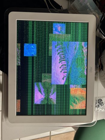
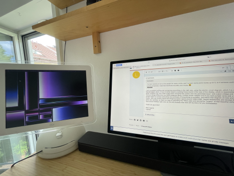
I’ve tried it a few times but everytime I get an image like the attached one. A bunch of noise all over. I‘ve tried shielding it a bit more but this is the best I can get.
I also use a screwed HDMI socket to avoid solder. The only wire that has a bit of solder on it is the purple one Connected to HDMI Pin 18, as I ripped of the connector accidentally.
The panel was working alright when I tried it before starting the conversion a couple of months ago.
Can it be something with the powersupply?
On my first attempts I was using the internal one with a too small converter, then I switched to an old 300W ATX powersupply before buying a proper one that will stay in it.
Any Idea would be highly appreciated.
That breakoutboard is awesome, I should have gotten it a couple of days ago
I‘ve attempted to do it myself these days as well but I‘m struggling a bit.
I’ve tried it a few times but everytime I get an image like the attached one. A bunch of noise all over. I‘ve tried shielding it a bit more but this is the best I can get.
I also use a screwed HDMI socket to avoid solder. The only wire that has a bit of solder on it is the purple one Connected to HDMI Pin 18, as I ripped of the connector accidentally.
The panel was working alright when I tried it before starting the conversion a couple of months ago.
Can it be something with the powersupply?
On my first attempts I was using the internal one with a too small converter, then I switched to an old 300W ATX powersupply before buying a proper one that will stay in it.
Any Idea would be highly appreciated.
Attachments
Hi, Theantal.
How is your setup right now? Are you using the dedicated breakout board?
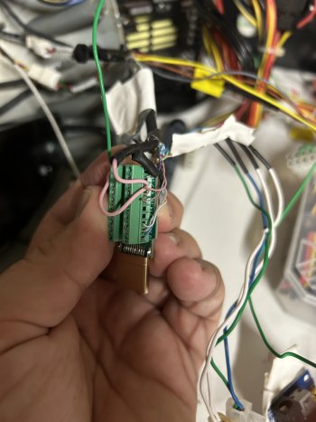
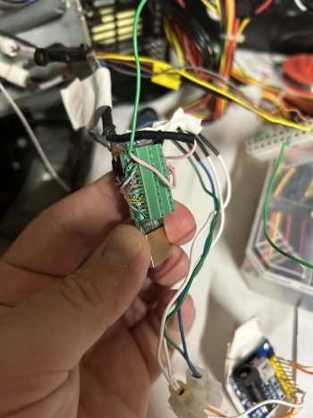
Can you take a photo that shows us how and which cables you have connected to the adapter board?
Assuming the display is working it could be as simple as a misplaced wire or two.
How is your setup right now? Are you using the dedicated breakout board?
Can you take a photo that shows us how and which cables you have connected to the adapter board?
Assuming the display is working it could be as simple as a misplaced wire or two.
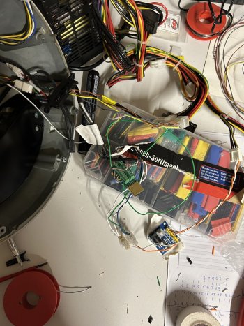
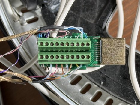
Here‘s my Setup, sorry looks somewhat yanky atm
I don‘t use the breakoutboard, but have attached most TMDS wires to the HDMI Plug directly.
Except for the 4 wires with 3.3V I had them attached to the ATX Powersupply directly, but suspected that that might be the source of noise, so I used a step down converter to convert the 3.3 V down from a different Powersupply with no success either. I don‘t have an oscilloscope at hand, so I can check if the PSU is noisy.
For some reason I have a strong feeling about noise, that it pics up something from somewhere, But I don‘t know for sure.
Checked the connection at the HDMI Port many times even switched them around but no success.
Its 20, 1, 2 …9 on the one side and 10-19 on the other
Should I try it with a new PSU?
I’ll be on a work trip all week so this will lay here for a while.
Any other suggestion?
Attachments
I am not so sure about using the ATX plug for powering the display... I think it should be alright but you will need another PSU in the end and I used a molex drive plug which provides 12v and 5v but let's assume the given voltages are good.
Things that I see right away:
I updated my connection table as I think there were some slight mistakes... please have a look.
(image removed)
Things that I see right away:
- Where is your 1K resistor between HDMI pin 18 and 19?
- I think that HDMI pin 18 needs 3.3 volts injected
- Still using the old connector to the inverter does make it hard to see which cables are going where - have you checked the right voltages
- HDMI 20 is ground? it only needs one connection afaik
I updated my connection table as I think there were some slight mistakes... please have a look.
(image removed)
Last edited:
Hi, yeah the HDMI Connector is quite hard to read and i'm sure about the connections on the inverter I'm pretty sure there is no issue there.
The resistor between 18&19 is in shrink tube, I put it in there, as I had the plug already assebled.
Are you sure about the 3.3 V on Pin 18? I measured 5V coming in from the attached HDMI Device.
I Measured Pin 20, its connected to the outer Metal of the HDMI Plug, so it is ground. Just wanted to make sure it has the right potential of the PSU.
I the orange black wire stuck a little bit at the outer shield of Plug, and it got pretty hot, so something leaked through there, thats the reason why I've added that extra ground.
I'll go and order a different Powersupply, will report back when I figured something out
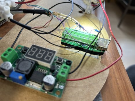
Hi again. I really haven't used my G4 display in a while but here is a close up from my working setup. It shoud look similar to yours. (the display really says 3.3v not 0.0).
If I find some time I'll disassemble my G4 again and take another photo to verify but it could take a while.
edit: the 5v are probably coming from the hdmi source as you connect it.

If I find some time I'll disassemble my G4 again and take another photo to verify but it could take a while.
edit: the 5v are probably coming from the hdmi source as you connect it.
Hello everyone,
I am trying to replicate the same thing with my 15" G4 iMac, but somehow am struggling.
When I plug in power and HDMI (first power then HDMI), I see a white screen (backlight) and I see the display as detected on my connected Macbook, however I don't see a picture on the iMac screen.
I have connected the cables as shown in the diagram attached.
What is a bit strange is that when I haven't plugged in HDMI the step-down shows 3.3V, but as soon as I plug HDMI in, the out-voltage rises to 4.3V which I can't decrease no matter how far I turn the screw.
Does anyone have an idea what the issue could be?
Is it ok that I connect everything to the same ground (the one from the PSU)?
Attachments
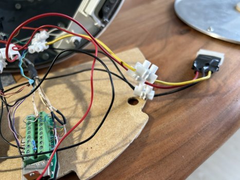
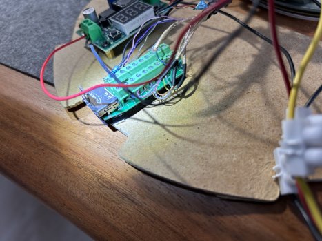
Hello there. I'm not that good at reading diagrams but due to the latest rise in interest here is my working iMac 15'' display disassembled for you convenience. Please refer to the photos.
As far as your questions go:
When screen power is turned on and hdmi is not powered or unplugged the display is greyish.
As you can see in the images I also have a common ground but I did use 12v as the input for the step-down converter.
If your step-down shows another voltage after connecting something to the HDMI power you must have mixed something up.
Attachments
-
 IMG_4740.JPG419.4 KB · Views: 142
 -
 IMG_4738.JPG440.7 KB · Views: 135
 -
 IMG_4739.JPG482.4 KB · Views: 134
 -
 IMG_4737.JPG509 KB · Views: 126
 -
 IMG_4736.JPG578.8 KB · Views: 133
 -
 IMG_4735.JPG815.8 KB · Views: 126
 -
 IMG_4734.JPG664.4 KB · Views: 132
 -
 IMG_4733.JPG662 KB · Views: 143
 -
 IMG_4733.JPG662 KB · Views: 137
Hi SantiCastX,
Thank you guys btw!
Best regards
Leander
I just succeeded building and connecting everything in the right way, using the electric circuit diagram, which I've shown Paardenkapper above. If your inverter board is working fine(a board in the case of the display, which is responsible for power supplies) you only need a step down converter(be careful with the permitted input- and output voltage and the minimal voltage difference), an HDMI-breakout Block, a Molex power adapter and if you want jumper wires and a little jumper board to connect everything nice and easy. If everything is available, just follow that diagram of mine and be careful. With the inverter board and shipping taxes I spent around 100€(109$). Maybe disassemble and storage the parts very carefully, so there is a way of rebuilding the TMDS cable and saving the "organs" of that beautiful computer. I have school holidays right now, so me and anybody else here will be there for you immediately!I've been keeping an eye on this project for quite a while, and I've been saving some money up for it, so if someone could list the components I need that would also be pretty nice, thanks
Thank you guys btw!
Best regards
Leander
Attachments
Looks interesting, but how do you use it, plug a hdmi into one end and the g4 monitor connector into the other, then what ?Really dumbing it down,
Unplug the TMDS cable and plug it into this:
HDMI to TMDS Breakout board by Stillwell Labs on Tindie
Breakout board for HDMI to TMDS
I'm having the same problem did you ever find a solution? Thanks in advance.Hello everyone,
I am trying to replicate the same thing with my 15" G4 iMac, but somehow am struggling.
When I plug in power and HDMI (first power then HDMI), I see a white screen (backlight) and I see the display as detected on my connected Macbook, however I don't see a picture on the iMac screen.
I have connected the cables as shown in the diagram attached.
What is a bit strange is that when I haven't plugged in HDMI the step-down shows 3.3V, but as soon as I plug HDMI in, the out-voltage rises to 4.3V which I can't decrease no matter how far I turn the screw.
Does anyone have an idea what the issue could be?
Is it ok that I connect everything to the same ground (the one from the PSU)?
Edit: NVM i figured it out thanks Landix for your awesome diagrams!
Last edited:
Hey all. Thanks for sticking with the thread and updating the diagrams etc.
great to hear that a few of you have made this work I am not one of them though!
it looks by the images that brown/black and red/black from the display are grounded, correct?
I’ve injected 3.3 to 18, green and blue, grounded 17, and am still only getting the gray screen. For those of you that got this working, what was the ‘aha’ that got it working? I’d really love to finally get this project complete but I am so stumped.
Hey all. Thanks for sticking with the thread and updating the diagrams etc.
great to hear that a few of you have made this work I am not one of them though!
it looks by the images that brown/black and red/black from the display are grounded, correct?
I’ve injected 3.3 to 18, green and blue, grounded 17, and am still only getting the gray screen. For those of you that got this working, what was the ‘aha’ that got it working? I’d really love to finally get this project complete but I am so stumped.
Do you have the 15 inch model? Please refer to the table I made above.
17 is ground
18 purple wire + one end of the resistor
If possible you could take some photos and post them here.
Yup, I've been following the posted charts and the revisions that have been made over time. 17 and 20, ground, blue and teal to 3.3v, 3.3v into 18 along with purple and resistor, resistor to 19. I'll try to clean up the wiring and take some pics. it's a bit of a patchwork as I've tried to get it all wired right.Do you have the 15 inch model? Please refer to the table I made above.
17 is ground
18 purple wire + one end of the resistor
If possible you could take some photos and post them here.
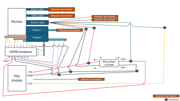
Hi all. As I'm currently at home with the flu and backpain I tried to visualize the connections again to make things even clearer. I think it should clarify which cable goes where and what voltage to apply.
This is the simplified version disregarding any voltage conversion.
Dotted lines are all GND and orange is +3.3v
(image removed)
This version is showing how to connect a stepdown converter.
We're using the 5V molex current and lower it to 3.3V
(image removed)
I hope this helps even more people. If you have any notes or remarks please reply so that I can correct the images.
Last edited:
Hi, not sure if anyone is still checking this. I"m trying to simplify this further, and not use a standard power supply.
Could I send USB power to a hub inside the iMac base, and use these USB to power adapters? One for each different power ammt?
Do I need the 1k resister?
What would I do about the grounds?
Has anyone used this? it worth the simplicity?
Could I send USB power to a hub inside the iMac base, and use these USB to power adapters? One for each different power ammt?
Do I need the 1k resister?
What would I do about the grounds?
Has anyone used this? it worth the simplicity?
You have to ask yourself whether you actually want some fun putting this together or have a perfect no frills solution. In my opinion the HDMI breakout is fairly simple - especially if you consider that I documented what to connect in detail above. It's up to you.
Regarding the power supply: I think most people will opt for a molex/drive power supply because it delivers 2A and 12 as well as 5V. I have seen some people use 5V instead of 3.3V and it somehow worked for them.
Regarding the power supply: I think most people will opt for a molex/drive power supply because it delivers 2A and 12 as well as 5V. I have seen some people use 5V instead of 3.3V and it somehow worked for them.
Hi, I think you need the molex adapter, because you need 12V and 5V. And if my memory works properly, USB can‘t offer 12V. I didn‘t use a resistor, but a step down converter, you can find links in this forum. Wish u luck!Hi, not sure if anyone is still checking this. I"m trying to simplify this further, and not use a standard power supply.
Could I send USB power to a hub inside the iMac base, and use these USB to power adapters? One for each different power ammt?
Do I need the 1k resister?
What would I do about the grounds?
Has anyone used this? it worth the simplicity?
Oh my goooooood, that would have been so helpful 😂. Just wanted to say, that u did a great job mate. Is it possible to pin this post to the top of this forum, so it‘s easier for the new ones to find?Hi all. As I'm currently at home with the flu and backpain I tried to visualize the connections again to make things even clearer. I think it should clarify which cable goes where and what voltage to apply.
This is the simplified version disregarding any voltage conversion.
Dotted lines are all GND and orange is +3.3v
View attachment 2438043
This version is showing how to connect a stepdown converter.
We're using the 5V molex current and lower it to 3.3V
View attachment 2438045
I hope this helps even more people. If you have any notes or remarks please reply so that I can correct the images.
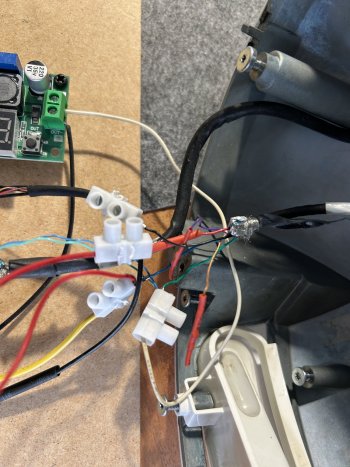
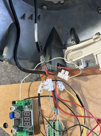
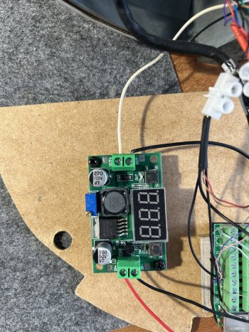
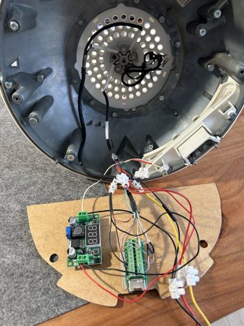
Ok, finally got a chance to revisit this.
I’m experiencing the gray screen, but also the output of the step down converter jumping from 3.3 to 4.3v once everything is powered up. I have confirmed everything to be connected as the wiring diagrams.
3.3v to green inverter
Gnd to black
5v to red
12v to blue
Gnd to 17 & 20
1k ohm between 18&19
3.3v to 18
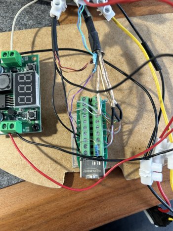
Breakout wired as pictured
Might lose my hair before this ends up working!
I’m experiencing the gray screen, but also the output of the step down converter jumping from 3.3 to 4.3v once everything is powered up. I have confirmed everything to be connected as the wiring diagrams.
3.3v to green inverter
Gnd to black
5v to red
12v to blue
Gnd to 17 & 20
1k ohm between 18&19
3.3v to 18
Breakout wired as pictured
Might lose my hair before this ends up working!
Attachments
At first glance I do not see an error in your wiring. Aside from the huge white wires you're using - don't you have thinner wires maybe?
Regarding the jump in voltage: the stepdown converter has an adjustable resistor with resistance R adjusted to X in Ohm.
R = U x I (voltage x ampere) and U = R x I
If the voltage jumps up it should mean that the power draw has increased.
I have read this somewhere before but it's usually down to using a multimeter and measuring your circuits.
I'd really start with replacing the fat white wires with thinner copper wiring and maybe look at your ground wiring.
Register on MacRumors! This sidebar will go away, and you'll see fewer ads.