Become a MacRumors Supporter for $50/year with no ads, ability to filter front page stories, and private forums.

USB3foriMac

macrumors 6502
Original poster
Apr 15, 2020
317
119
Singapore
Hi all, I'm looking for a schematic diagram of the 27" 2009-2011 models power supply, my model number is PA-2311-02A (LiteOn branded).
If you happen to have the one of model ADP-310AF, I appreciate this, too. I have repaired several standard switch mode supplies, but Apples is more complex, with PFC and resonant mode controller. It is the latter (NCP1396A) which does not get correct supply voltage on the primary side. It is hovering around 10V only, but since the supply is using the 1396A version, it should probably be more. As such, the control is not working correctly. My output is only 8V on the secondary.
The design is somewhat different from the 'typical application' in the data sheet. Can't locate where the supply for pin 12 is coming from (R8), and neither the equivalent to the Zener diode D3. Possibly as a result of low supply voltage, pin 11 does not deliver any voltage. With Vgs=0, M2 is never conducting. That's probably the reason why the secondary voltage is wrong.
Thanks in advance for helping.

Screen Shot 2020-06-27 at 2.46.14 AM.png
 

USB3foriMac

macrumors 6502
Original poster
Apr 15, 2020
317
119
Singapore
Found an application note from the maker of the chips. Their circuit design is nearly identical to the LiteOn model, except for the auxiliary voltage ("17V" in the application note), generated by another IC (NCP1027).
LiteOn uses discrete circuitry for that, and not having a circuit diagram makes tracing connections and identifying components a tedious task. But I hope I'll get there, this is also fun.
If anyone wants to contribute, please do so.
Screen Shot 2020-06-28 at 2.58.50 PM.png
 

Attachments

  • NCP1396 NCP1605 supply.pdf
    1.2 MB · Views: 4,326

USB3foriMac

macrumors 6502
Original poster
Apr 15, 2020
317
119
Singapore
I found the issue.
To add to the first post: if in standby, the voltage at those IC is indeed 10V. When PS_ON is bridged too GND, the supply awakes. Those IC on the primary side will run with approx. 17V.
My secondary output voltage was only 8V. There are two Op-Amps on the secondary side, AS324 and TSM104. The TSM104 is responsible for the voltage stabilization. One of the resistors in that circuit had a cold solder joint.
Now it is working correctly again.

Having studied the entire circuit, I have to say that this is a great 12V supply. It is designed for extremely low power dissipation and high efficiency. It features current sensing and temperature monitoring. In general, it is designed for long lifespan. Love it.
 

TwoH

macrumors 6502
May 19, 2019
464
333
Nice find, OP. Interesting to see - shame I don't have schematics for any of the PSU for iMac else I would've helped earlier.
 

drscoot

macrumors newbie
Feb 11, 2021
9
1
I just found your post, I have exact the same PSU from my imac2011 27". Also this power supply is dead. I have it out of the imac and tested, but all I can measure on the 16 pin connector is 0,94VDC at SMB_ACDC_SCL_RC (pin 7) and 0,85VDC at SMB_ACDC_SDA_RC (pin9). Even after short PS_ON to GND, no change.
I can't find the NCP1396A you mentioned. I dead some searching on YT & Google, but almost nothing to find about these PSU.
Can you share more diagnostic tips?
Would you consider making a repair video to post on Youtube? I think that would be helpfull to lot of people.
 

USB3foriMac

macrumors 6502
Original poster
Apr 15, 2020
317
119
Singapore
I've provided some guidance in thiss thrthread successfully. While it's not the same supply, the steps and checks are the same.
The 1605 and 1396 are the 2 IC on the solder side, bottom.
When measuring at the DC output, you can forget about the SMB pins. This is digital communication so your multimeter won't measure anything useful.
Check the DC out instead.
However, mostly the primary side power MOSFETs die, so you risk blowing your fuse when powering up.
You need to check those out first. Instructions in the thread mentioned above.

I don't have a YT account, but I'll consider creating one for this. Tips welcome...
 

drscoot

macrumors newbie
Feb 11, 2021
9
1
Well I had look at the linked thread about the newer iMac 21" with the housefuse that keeps jumpin.
But my LiteOn PSU is not blowing fuses, it is stone dead, no reaction at all.
I measured the fuse and bridge rectifier, but I'm not sure where T1/T3 are and what their pinlayout is, to do some more measuring.
Maybe you can some more instructions or photos about this Liteon PSU?
I found the chips 1396 and 1605,they are covered with some protective gum. Not sure on what pins I can measure here.
There are lots of video's on youtube explaining how to start with a channel. It is really easy, try a search on 'start a youtube channel' or similar.
 

USB3foriMac

macrumors 6502
Original poster
Apr 15, 2020
317
119
Singapore
But my LiteOn PSU is not blowing fuses, it is stone dead, no reaction at all.
You will have to check the primary part first. Likely the problem can be found here.
IMG_20200627_141639.jpg

WITHOUT POWER:
* Check the fuse F001, need to be ~0 Ohm
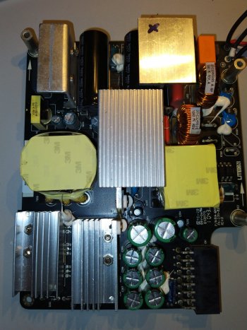
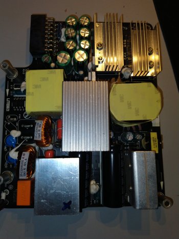
* Check the rectifier diodes with diode tester. It is under the heatsink next to the orange "CARLI" capacitor C001. Follow the notes above/in the other thread.
* Check Q1, Q2 and Q3 as per image below, which follows the naming of the schematic above. How to check, see other thread.

I measured the fuse and bridge rectifier, but I'm not sure where T1/T3 are and what their pinlayout is
Here are the notes that I took for myself, with designations of some critical parts. The designation of the parts follow the schematic above. T1 and T3 are Q1 and Q3 (naming mixed up, but it refers to the same part).
Don't forget Q2 which is pretty much across + and - of the 400V DC. In your case, Q2 should be ok, otherwise the fuse would blow. If fuse is blown (F1), definitely check Q2.

After you have done all that, check all the diodes. Don't forget the one that sits next to Q2 on the same heatsink. Use the diode tester on the multimeter. There should be ~0.3V in one direction and no connectivity in the other. If in doubt, check using Ohm function. If low ohmic in both directions, the diode is shorted. A short is the most frequent failure type. You will hardly see an open circuit.

IMG_20200627_141601 markup.jpg
thhis is

So let us know what you found.

If there is no problem on the primary, there might be a diode short on the secondary side. This is the most likely failure.
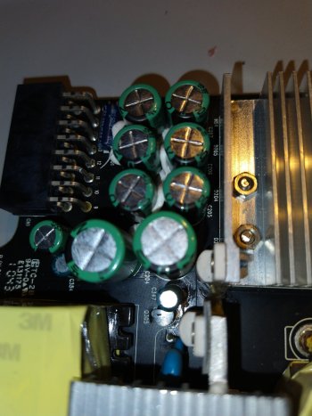
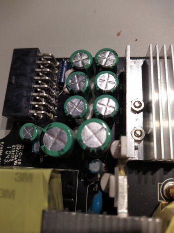
The diodes are double-diodes (Anode - common Kathode - Anode) and are located under the heatsink next to the bunch of green capacitors. Designation D200 to D205 on the PCB component side.

If you didn't find any issue so far, you can check WITH POWER. MAKE SURE YOU DON'T ELECTROCUTE YOURSELF. THIS IS HIGHLY DANGEROUS. DO NOT TOUCH ANYTHING DURING MEASUREMENT.

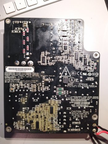
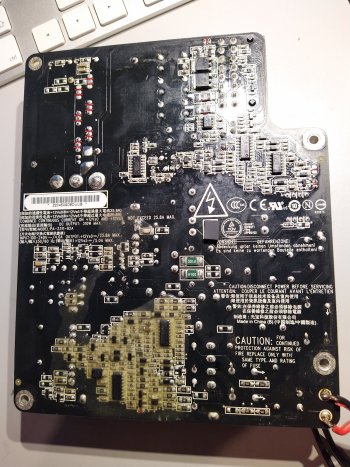
First, shorten PS_ON with GND. This means on the 16-pin DC output connector, shorten pin 6 with 5 or 7. (see image PCB side for pinning.)

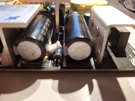
Check the high voltage (designated 400V) across the capacitor. For a 230V country, you will measure ~320VDC. If 110VAC, then ~155VDC. If this is present, that's good so far.
Check on the secondary side across any of the bunch of capacitors. If you have 12V, then your supply is working in principle and one of the output-enable FETs is not working. These are on the solder side, the two black square FETs P0603BDG next to the DC connector pins 11 to 14.
1614153183402.png

SWITCH POWER OFF. Check same as Q1/2/3.
 
  • Like
Reactions: StorePeter

drscoot

macrumors newbie
Feb 11, 2021
9
1
That's a lot of help, for me;
My measurements so far:

diodemode:
Bridgerectifier Red on + and Black on each of the ~ = 0,50V switch probes= OL. >OK
Bridgerectifier Black on - and Red on each of the ~ = 0,50V switch probes= OL. >OK
Note: in the other thread you said: value e.g. 300 to 700’ I suppose that is mV?
Can it be that in your photo of the solder side that you swapped the + and - symbols for the bridge? I measure the outer way around.
Q1 Red on S and Black on D = 0,50V, switch probes= OL >OK
Q2 Red on S and Black on D = 0,50V, switch probes= OL >OK
Q3 Red on S and Black on D = 0,50V, switch probes= OL >OK
D next Q2 0,4V and OL >OK
D301 0,4V and OL >OK
D302 0,4V and OL >OK
D13 0,4V and OL >OK

Ohmsmode:
F001 0Ohms >OK
Q1 Red on S and Black on D = OL, switch probes= 7MOhm >OK
Q2 Red on S and Black on D = OL, switch probes= 1MOhm >OK
Q3 Red on S and Black on D = OL, switch probes= 7MOhm >OK


D200 D201 D203 D204. I’m not able to measure these, in diode mode I get beep in each direction
In Ohmsmode I measure very short time about 5Ohms (just enough to see on DMM then rising to +100Ohms. Same story in other direction.
D202 not installed

Now going for AC230 live test:
230VAC after the fuse incoming
330VDC on each of the 2 big cap's, 330VDC is there even without enabling the PSU
but no 12VDC on the 6 small caps!
On the 17VDC point it looks like I have a fluctuating voltage 7-14VDC. 1sec up 1sec down....
 
Last edited:

USB3foriMac

macrumors 6502
Original poster
Apr 15, 2020
317
119
Singapore
Note: in the other thread you said: value e.g. 300 to 700’ I suppose that is mV?
Yes. It depends how your multimeter displays the forward voltage during diode test. So that's 0.3V to 0.7V.

Can it be that in your photo of the solder side that you swapped the + and - symbols for the bridge? I measure the outer way around.
+ and - on the bridge rectifier show the "output" of the rectifier. So at the "+" pin you will see positive voltage when you measure voltage when switched on. For a diode test, you measure from "~" to "+" for example. In the picture below, this would be the top left diode. To have this diode conducting using a multimeter, you need to apply the positive probe at "~" and the negative probe at "+". So nothing is reversed. The difference/confusion is due to the fact that your multimeter applied a voltage across the diode between "~" and "+" when in diode tester mode, whereas you measure a voltage between "+" and "-" when in multimeter mode. So ytwo entirely different things, both correct.
1614303456966.png


D200 D201 D203 D204. I’m not able to measure these, in diode mode I get beep in each direction
In Ohmsmode I measure very short time about 5Ohms (just enough to see on DMM then rising to +100Ohms. Same story in other direction.
D202 not installed
There is a huge capacitive load, you need to be patient. You see the "A1 K A2" printed on the component side.
So you put your positive probe on K, and the negative on A1, later A2. This would be the inverse direction and the diodes should not conduct. However,you would see a voltage starting from 0V rising up, above 1V and further. You are chargingn the capacitors. If that's the case, the diodes should not be short circuited. Do this for all diodes. Some are parallel, so the starting voltage will be where you left off during another measurement and not 0V.
the ohms measurement is also helpful, you can do that in all directions. If it remains at low ohm, there is a short. If it's ok, the ohms should keep on rising from 0 Ohm upwards, well above 20 ohms. If you are above 20 ohms there is no diode short, but a capacitor could still have a leak.
Can you take a good photo of the capacitors? If any capacitor is bulged, they are spoilt and must be replaced.

If the diodes are ok, your problem could be in the auxiliary power circuitry. Mine was ok, I did not further analyze this part of the circuit, see pic below.
Check the marked green parts, these are diodes.
The yellow marked are transistors. As I did not have a problem in this circuit, I have not tried to figure out what part numbers these are. The part number is coded in 3 letters, such as "KY4". The shape of the parts is called "SOT23". So you could search for "SOT23 transistor KY4" or "SMD marking KY4" or so.
What I suggest is use diode test to check whether any of them has a short circuit between any two pins. You might also measure one or two forward voltages, depending what parts these are (bipolar transistor or Mosfets). As long as there is no short they are probably ok. If you measure ohms, nothing should be close to 0 ohms. I know this is a bit vague, but a rough measurement should be sufficient.

IMG_20200627_142236.jpg


That's all for now, I don't have much time today to help further. Maybe you are lucky and found the problem already.
 

drscoot

macrumors newbie
Feb 11, 2021
9
1
Thanks for the respons, all such details are very helpfull. Do you have your PSU on the bench or can you tell all this info out of your head?
Caps were the first I looked at, nothing bulged or leaked. First I thought 1 of the 2 small Elco's has leaked (the one just above 3M marking on the yellow), took it out and measured it with my cap-meter but it was good. Suppose it was fluxmarking then. PCB is cleaned now.

D200 -D204: I was able to measure them just like you said, keeping in mind the caps are charging. Voltage and omhs are is rising. It looks they are all in parallel, I always see the value where I left the other. Looks OK to me.

SOT23 transistors
3th from left: 'WCH' followed by an even smaller text and 90° angled, '90' can't find it
2nd from left: KYC 6X > BZX84B33 or BZX84C33 Z-diode with 1 pin NC, pin 3 single sided =K
1st from left: S72 >2N7002 N-Channel Mosfet 1:G 2:S 3:D. 3 is single side, S/D measure OK

4th from left KY4 6X >BZX84-C15 Z-diode
5th WC8 60 > can't find it, I'm pretty sure it is correct WC8 ?
Not sure if I can measure z-diode in circuit? No short measured.
I'm wondering if, on the 17VDC point, if the fluctuating voltage 7-14VDC, is OK?
 

Attachments

  • IMG_20210226_222958_1.jpg
    IMG_20210226_222958_1.jpg
    705.7 KB · Views: 969
  • IMG_20210226_223013_1.jpg
    IMG_20210226_223013_1.jpg
    726.8 KB · Views: 861
  • IMG_20210226_223033.jpg
    IMG_20210226_223033.jpg
    513.8 KB · Views: 736
  • IMG_20210226_223052.jpg
    IMG_20210226_223052.jpg
    436 KB · Views: 629
  • IMG_20210226_223103.jpg
    IMG_20210226_223103.jpg
    526.7 KB · Views: 719
  • IMG_20210226_223138.jpg
    IMG_20210226_223138.jpg
    369.5 KB · Views: 589
  • IMG_20210226_223148.jpg
    IMG_20210226_223148.jpg
    383.6 KB · Views: 544
  • IMG_20210226_223201.jpg
    IMG_20210226_223201.jpg
    311.5 KB · Views: 684

USB3foriMac

macrumors 6502
Original poster
Apr 15, 2020
317
119
Singapore
I'm looking mostly at my old documentation. Also, I have a spare supply I am looking at now and then, in order to validate my statements.
The 17V is definitely wrong. This should be stable. Your supply is not properly starting up. Often a reason for that is a short on the secondary side, subsequently the primary shuts down again, or a part in the primary circuit itself. As a result, the NCP1396 IC detects a fault condition and shuts down.
I haven't analyzed the 17V generation circuit partially because the PCB tracks are not easy to follow. So you did some good job here. Z-diodes can't be checked with the multimeter as the Zener voltage is too high for the multimeter. Since diodes mostly short circuit, I would assume they are ok if they don't show a short circuit when measuring Ohm.
1614487473562.png

On the components, you are correct, some are diodes or Zener diodes. The components marked KYC (2fl), WCH (3fl) and KY4 (4fl) have pins 1 and 2 commoned via a PCB track. These would likely not be transistors but diodes.
My 1st from left reads 12W and is definitely a transistor. Pin 2 is connected to 0V.
Diode KY4 (4fl) also has pins 1&2 to 0V.

The fluctuation on the "+17V" is of course not ok. The voltage on this pin is stable 14.6V on mine.
What would help here is a circuit diagram, but I am certain the fault is not in this part of the circuit.
If you have a scope, you can check on this pin to see if the voltages pulses. This is likely what you see with your multimeter. As a result, you measure somewhat of an "average" or even "random" voltage due to the slow speed of the mulltimeter.
So likely this part of the circuit is correct, but it is controlled to switch off due to a fault condition detected by the NCP1396A IC.

There are a few more components in the so-called "resonance circuit" that could be faulty, or the Ic itself could be damaged. Testing of the IC will require a scope. The other components can be tested, but some require desoldering.

Check the diodes indicated "D" in this picture.
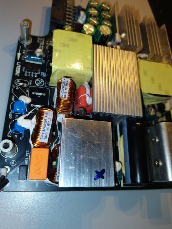
The two capacitors marked "C" need to be unsoldered and measured for actual capacitance. These are the two orange blobs glued together, between coil and heatsink.
1614490836648.png

IMG_20200627_142236 markup2.jpg

The value of these is pretty critical. the schematic above shows 33nF. Having two in parallel means each should be half of that.
I never unsoldered mine, so I do not know what LiteOn used here. It can be different from the 33nF from the generic schematic.
If this value drifts off, the resonance circuit (these caps plus the large inductor next to them with the yellow tape) won't work properly, and this will be detected. The inductor should be ok, unless you dropped the entire supply and the inductor ripped out of the PCB.

Those will probably be my last suggestions, unless you can get hands onto a scope, then we can continue a little bit more.
 

drscoot

macrumors newbie
Feb 11, 2021
9
1
Well I have an old scope here available, 2Ch 20Mhz with CRT. But not sure if I need an isolator transformer before taking any measurements on the 230V live-PSU?!?
But hold on, I think I found a shorted diode! The one at the right in your photo nearby the letters AT. I try to desolder this one.
The others diodes are OK, except the 2 together at the left, I see a normal forward voltage 0,5V but reverse I get 2V? Both are like this.
 

USB3foriMac

macrumors 6502
Original poster
Apr 15, 2020
317
119
Singapore
Well I have an old scope here available, 2Ch 20Mhz with CRT. But not sure if I need an isolator transformer before taking any measurements on the 230V live-PSU?!?
But hold on, I think I found a shorted diode! The one at the right in your photo nearby the letters AT. I try to desolder this one.
The others diodes are OK, except the 2 together at the left, I see a normal forward voltage 0,5V but reverse I get 2V? Both are like this.
If your scope is AC powered, your probe negative is likely grounded. So don't use it without isolating transformer. I Iuse a battery operated one to avoid such issues. But even then, use it without charger plugged in (for those who read this and want to follow).
The diode on 5he right is part of the resonance circuit and will be quite stressed. Wouldn't be surprising if it's spoilt.
The others, I'll check it out withy meter another day, ok? Too busy today and tomorrow.

Edit:
I checked the diodes on my board, same results for all three of them. The one on the right near "AT" appears to be short. Likely this diode is parallel to the inductor and is a free-running diode. Probably ok.
That leaves you with all diodes ok, it seems.
A scope would help to check operation of the ICs as well as the power MOSFETs.
Maybe time to make a video....
 
Last edited:

drscoot

macrumors newbie
Feb 11, 2021
9
1
I took one of the 2 orange Carli cap's out. It is marked:
CARLI 105K
MPH 450HF
100423A26
So 105K = 10nFx10000 = 1microF and I measured it as 960nF with ESR=0,62Ohm, K stands for 10%, that looks OK.
The 450 is 450VDC Halogen Free as I can make up from here on p5: http://www.powertipusa.com/dtell/upload/files/120607 MTF SERIES SPEC.pdf
It looks like these 2 are in parallel on the pcb.
The second cap measured 950nF ESR=0,78Ohm >OK
Hard to remove those 2, now trying to get them back in.

Yes my scope is powered by 230VAC and I'm missing the earth wire for the probe somehow.
 

USB3foriMac

macrumors 6502
Original poster
Apr 15, 2020
317
119
Singapore
Yes, 1uF, 2 in parallel makes it 2uF. 960nF per cap should be acceptable, at least it's within the tolerance. Quite different from the 33nF in the generic schematic.
PM me once you have a portable scope. In the meantime, maybe I find the time and skills to make a video. Just a bit busy recently and in the near future...
 

drscoot

macrumors newbie
Feb 11, 2021
9
1
I complete understand you're spending here a lot of time at. All the help and tips are greatly appreciated so far.
For me it is a learning phase and there is almost no info about these PSU's despite all the iMac videos available.
There is no hurry, I have another iMac27 for dialy use.

I did some research on measuring a switch mode PSU with a scope. As I understood it would be OK to use this mains connected scope on a 230V PSU, as long as I keep the earth lead of the probe connected to the ground point on the PSU.
But of course when you put the probe point and earth lead over one component or in a circuit, there is risk of shorten it badly!

On the other hand I saw the Hantek 2D72 which looks like a nice portable scope in addition to my old CRT scope, for about €150 with even a signal generator and DMM. 3x more than a new PSU, but that is not why we doing it for ;).
 

The_Croupier

macrumors 6502
Oct 11, 2018
419
284
Can you PSU gurus tell me what these digits are on the resistors?

516 or 915 I'm guessing the slight bulge on the bottom of the 2nd digit (1) is indicating that it I should be reading it as 915, so im looking for 9.1 MΩ resistors and some 0 Ω bridge resistors i guess.

Good PSU
IMG_20210323_221921.jpg

Bad PSU
IMG_20210323_221818.jpg
 

Nguyen Duc Hieu

macrumors 68040
Jul 5, 2020
3,001
995
Ho Chi Minh City, Vietnam
Can you PSU gurus tell me what these digits are on the resistors?

516 or 915 I'm guessing the slight bulge on the bottom of the 2nd digit (1) is indicating that it I should be reading it as 915, so im looking for 9.1 MΩ resistors and some 0 Ω bridge resistors i guess.

Can you tell us your multimeter reading off the R171 & R179 on the good and bad PSU?
 

The_Croupier

macrumors 6502
Oct 11, 2018
419
284
I'm not getting any reading from the resistors in that area, in fact most resistors on the primary are giving me nothing (
Secondary, nearly all resistors giving a value.

Looks like this might be to much for my limited knowledge to figure out...
 

USB3foriMac

macrumors 6502
Original poster
Apr 15, 2020
317
119
Singapore
Can you PSU gurus tell me what these digits are on the resistors?

516 or 915 I'm guessing the slight bulge on the bottom of the 2nd digit (1) is indicating that it I should be reading it as 915, so im looking for 9.1 MΩ resistors and some 0 Ω bridge resistors i guess.
Unfortunately, there are various codings, and you need to determine (best through measurement) which coding applies.
The usual coding is "xyz" (xyz being numbers) where the value is xy * 10^z. Example: 123 = 12 * 10^3 = 12,000 = 12k.

Your resistors are marked 915, and above coding applies. The value is 91 * 10^5 = 9,100,000 = 9.1M
These resistors have only a safety function, you can leave them alone. I do not have a ADP310AF here right now, but it looks as if they are going to ground. This is likely for EMC purposes, hence also the high values.

For the tiny tiny resistors Apple uses, there are different coding schemes involving a letter.

For 1% values:

smt_3digit.jpg


For 2%, 5%, 10%:

pth-and-smt-component-identification-and-understanding-40-638.jpg
 

The_Croupier

macrumors 6502
Oct 11, 2018
419
284
Unfortunately, there are various codings, and you need to determine (best through measurement) which coding applies.
The usual coding is "xyz" (xyz being numbers) where the value is xy * 10^z. Example: 123 = 12 * 10^3 = 12,000 = 12k.

Your resistors are marked 915, and above coding applies. The value is 91 * 10^5 = 9,100,000 = 9.1M

For the tiny tiny resistors Apple uses, there are different coding schemes involving a letter.

For 1% values:

View attachment 1748914

For 2%, 5%, 10%:

View attachment 1748915
Very useful information, thanks.
 

USB3foriMac

macrumors 6502
Original poster
Apr 15, 2020
317
119
Singapore
Can you PSU gurus tell me what these digits are on the resistors?

516 or 915 I'm guessing the slight bulge on the bottom of the 2nd digit (1) is indicating that it I should be reading it as 915, so im looking for 9.1 MΩ resistors and some 0 Ω bridge resistors i guess.

Good PSU
View attachment 1747949
Bad PSU
View attachment 1747950 As
Seems R171 is damaged and R179 is gone. Both are 0 Ohm.
These parts will likely not be critical and cause your problem. I believe your issue is elsewhere.

Have you checked your Mosfets and all diodes?
 
  • Like
Reactions: The_Croupier

drscoot

macrumors newbie
Feb 11, 2021
9
1
Apparently these resistors are not from the Lite On model PA-2311-02A PSU but for an ADP-310AF model of the Dominexus brand if I'm right. The layout is total different of min broken Lite On. Can't help with any measures here.

Anyway I have my battery operated scope now ready to further test out my dead PSU.
Any tips, on what are the important check points to probe, are more than welcome.
 

The_Croupier

macrumors 6502
Oct 11, 2018
419
284
Seems R171 is damaged and R179 is gone. Both are 0 Ohm.
These parts will likely not be critical and cause your problem. I believe your issue is elsewhere.

Have you checked your Mosfets and all diodes?
I'm away ATM but will check later
 
Register on MacRumors! This sidebar will go away, and you'll see fewer ads.