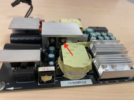
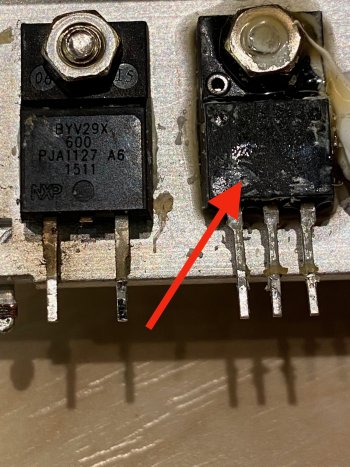
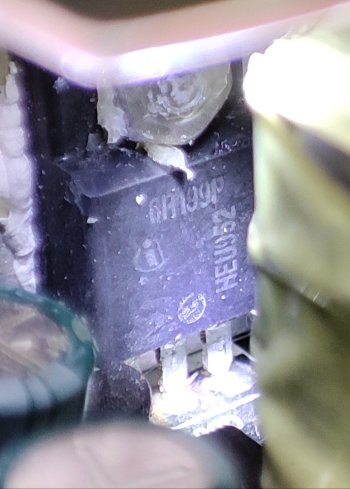
So I measured the "+17V" point vs GND (on the primary side), this is 14.62VDC, same whether PS_ONM is shorted to GND or open. That's probably correct, since the supply always delivers 12V as standby voltage.
So you can check that voltage for me.
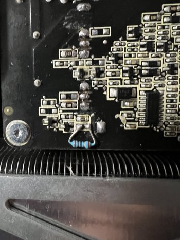
I also measured at the Optocopulers. You need to be careful not to short any pins during measurement. It is not dangerous for you since the voltage is small, but since they affect the 12V voltage stability, you could potentially drive up the voltage to a level where some components could get damaged. I wouldn't try.
A->B is "PC300", C->D is PC301. So you can also measure on the top side if you prefer.
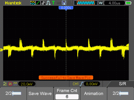
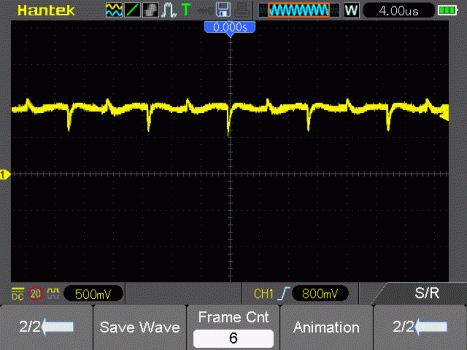
I check with a scope, and the voltage is basically stable when there is no load. From A (+) to B (-), I measure 1.07VDC. From C to D, I measure 0.88VDC.
View attachment 2112372
I also check with a scope, and you can see the voltage in attached gifs. The AC fraction on A->B is only 40mVpp, so that I had to couple AC. This waveform would be elevated by 1.07VDC.
For C->D, the AC fraction is around 500mV, so I could couple DC and still see the signal. The DC offset is 0.88V.
If the optocouplers are degraded, the signal would go to either a maximum or minimum, in order to try to adjust the voltage.
So measure these two signals carefully.
Also, when PS_ON is not grounded, check the voltage on supply connector pin 4 (versus GND).
With PS_ON grounded, check the same, plus a voltage at pins 15 respectively 13 to GND. On a good supply, these would all be 12V. If your PS_ON FET is defect, pin 4 would still be 12V, but the others might be any voltage (normally remain at 0V, but could be floating).


