You will have to check the primary part first. Likely the problem can be found here.
View attachment 1734429
WITHOUT POWER:
* Check the fuse F001, need to be ~0 Ohm
* Check the rectifier diodes with diode tester. It is under the heatsink next to the orange "CARLI" capacitor C001. Follow the notes above/in the other thread.
* Check Q1, Q2 and Q3 as per image below, which follows the naming of the schematic above. How to check, see other thread.
Here are the notes that I took for myself, with designations of some critical parts. The designation of the parts follow the schematic above. T1 and T3 are Q1 and Q3 (naming mixed up, but it refers to the same part).
Don't forget Q2 which is pretty much across + and - of the 400V DC. In your case, Q2 should be ok, otherwise the fuse would blow. If fuse is blown (F1), definitely check Q2.
After you have done all that, check all the diodes. Don't forget the one that sits next to Q2 on the same heatsink. Use the diode tester on the multimeter. There should be ~0.3V in one direction and no connectivity in the other. If in doubt, check using Ohm function. If low ohmic in both directions, the diode is shorted. A short is the most frequent failure type. You will hardly see an open circuit.
View attachment 1734449thhis is
So let us know what you found.
If there is no problem on the primary, there might be a diode short on the secondary side. This is the most likely failure.
The diodes are double-diodes (Anode - common Kathode - Anode) and are located under the heatsink next to the bunch of green capacitors. Designation D200 to D205 on the PCB component side.
If you didn't find any issue so far, you can check WITH POWER. MAKE SURE YOU DON'T ELECTROCUTE YOURSELF. THIS IS HIGHLY DANGEROUS. DO NOT TOUCH ANYTHING DURING MEASUREMENT.
First, shorten PS_ON with GND. This means on the 16-pin DC output connector, shorten pin 6 with 5 or 7. (see image PCB side for pinning.)
Check the high voltage (designated 400V) across the capacitor. For a 230V country, you will measure ~320VDC. If 110VAC, then ~155VDC. If this is present, that's good so far.
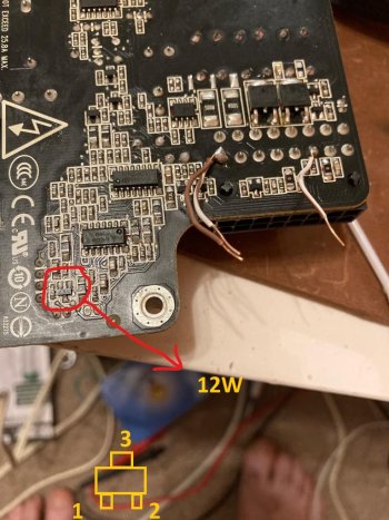
Check on the secondary side across any of the bunch of capacitors. If you have 12V, then your supply is working in principle and one of the output-enable FETs is not working. These are on the solder side, the two black square FETs P0603BDG next to the DC connector pins 11 to 14.
View attachment 1734463
SWITCH POWER OFF. Check same as Q1/2/3.


