Become a MacRumors Supporter for $50/year with no ads, ability to filter front page stories, and private forums.

MacTech68

macrumors 68020
Mar 16, 2008
2,393
211
Australia, Perth
I'm also trying to fix a 400K drive that has a motor problem. It can write disks, but such disks cannot then be read by other drives. Also, disks wrote by other drives cannot be read by this faulty unit. Do you guys think that this problem can be related to the Hall sensors or to the controller itself? Other components on the motor board appear to be fine. If I swap the motor board with another motor board from a working drive, then the unit works fine with the known good floppies.

I also have a question for mosaiko. I'm trying to repair the broken gears from 800K floppy drives too.
Can you give me a hint on how to do that? I tried doing a rubber mold and resin cast, but the final part was full of little bubbles and broke easily.
Can you give me directions, or can you sell me your replicas? Thank you.

It looks like the speed is set with the CX069A IC (if the circuit diagram above is correct). The speed seems to be set via a factory selected resistor.

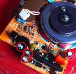
I'd be looking at the capacitors associated with that part of the circuit (marked with red circles below).

Of course, that's just a WILD guess, but if it can read and write it's own disk, I can't imagine anything else except speed as a cause. Jitter seems unlikely, otherwise it probably wouldn't be able to read it's own disks.

Does the drive do it's NORMAL speed changes when the head is at different radii from the hub?
 

Attachments

  • Speed Circuit Elect Caps.jpg
    Speed Circuit Elect Caps.jpg
    50.8 KB · Views: 298

maczo

macrumors newbie
Dec 25, 2014
28
4
Italy
Thank you very much for your help. :)

I've already checked the capacitors with my ESR meter and also verified capacitance (without desoldering though) but will eventually try to replace them with new caps.

I heard changes in speed but I'm not sure if they're related to radius. I should find a way to check this. Any suggestions?

I confirm the similarity of the following board schematic, on page 71: https://archive.org/download/bitsav...602/Sony_OA-D32_Microfloppy_Service_Nov83.pdf

(motor board part is BHC-2101A in that document, while BHC-2101C on my Mac floppy motor board).

On page 75 is a component listing. The CX069(A) IC that you suggested as a possible culprit is layed-out on page 77, though I can't find a detailed datasheet online.
 
Last edited:

MacTech68

macrumors 68020
Mar 16, 2008
2,393
211
Australia, Perth
I wish there was an easy way to check the speed. Swapping components from a known good motor board is prone to problems because the speed is fixed at the factory via the resistors across pin 1 and 8 of the CX069.

These drives will change their speed depending on the head's distance from the hub. IIRC there are 3 or 4 different speeds. This makes adjusting the speed WITHOUT a test rig near impossible.

The only thing I could suggest is creating a strobe disk (appropriate for your AC cycle - 50 or 60hz) and fixing it to the hub and comparing it to a known good drive. One of the speeds is likely to be 600rpm (though Apple and Sony might have selected anything).

Of course, I could be completely wrong and your faulty drive is NOT related to speed. The only other thing affected by swapping the motor board is track alignment but I thought the position of the motor board is fairly precise. Again, without an alignment rig and a proper test disk (worth several hundred dollars) it's NOT an easy thing to test.

EDIT: Here's a thought. Record the audio of the faulty drive and a good drive whilst formatting a disk. You might be able to use software to analyze the frequency of the sounds. That's without a CRO of course.
 
Last edited:

MacTech68

macrumors 68020
Mar 16, 2008
2,393
211
Australia, Perth
Yours is a very good idea (to use audio recording). I'm going to try that! :)

The RPMs are 5, and can be found here (lots of useful info too):
http://mirrors.apple2.org.za/Apple ...s/Apple 400k Floppy Disk Drive - 6990285A.pdf

From the schematics before, I don't understand why pin 6 of CX069A IC is never used. It is referred to as "output".

Some interesting reading there. I hadn't seen that technote before.

So from that, Apple is actually using the slower "speed 1" setting 394 to 590RPM (Page 33 and note at the bottom of Page 36).

Also, the speed is set via the host computer using the PWM signal and is monitored back via the Tach data signal. I suspect the Tach label is derived from SONY's "MINDEX" which is fed directly from one of the the hall effect sensors via an amp circuit. Interesting that many states of the drive are read via the RD signal when the 4bit input SEL,CA0,CA1,CA2 are set (page 18). It would be interesting to see where this PWM signal is introduced to the motor board. Is Apple NOT using the FG track?
 

mosaiko

macrumors member
Original poster
May 21, 2014
31
2
Italy - Bologna
I also have a question for mosaiko. I'm trying to repair the broken gears from 800K floppy drives too.
Can you give me a hint on how to do that? I tried doing a rubber mold and resin cast, but the final part was full of little bubbles and broke easily.
Can you give me directions, or can you sell me your replicas? Thank you.

Arrived too late :) good that you solve with the guy that print the gear with the 3D print. ;)
 

maczo

macrumors newbie
Dec 25, 2014
28
4
Italy
Thank you, mosaiko, let's hope them to be sturdy. I'll keep you updated. BTW, how did you do to make yours?

Interesting that many states of the drive are read via the RD signal when the 4bit input SEL,CA0,CA1,CA2 are set (page 18). It would be interesting to see where this PWM signal is introduced to the motor board. Is Apple NOT using the FG track?

I wrote a program to "query" the RD signal through the parallel port of a PC. I can move the head, start the motor and read the status signals, eject disks, but there's not enough data-rate using the LPT to actually read/write data to a floppy. Also I wasn't able to generate a suitable PWM signal (22 KHz with varying duty cycle) using LPT. But the 400Kb drive requires the PWM to be provided from the host computer, and the first Macintosh did that by routing a 22KHz signal from the sound generation circuits. Later Macintoshes did not (that's why you cannot connect a 400Kb floppy drive to them).
 

MacTech68

macrumors 68020
Mar 16, 2008
2,393
211
Australia, Perth
TI wrote a program to "query" the RD signal through the parallel port of a PC. I can move the head, start the motor and read the status signals, eject disks, but there's not enough data-rate using the LPT to actually read/write data to a floppy. Also I wasn't able to generate a suitable PWM signal (22 KHz with varying duty cycle) using LPT. But the 400Kb drive requires the PWM to be provided from the host computer, and the first Macintosh did that by routing a 22KHz signal from the sound generation circuits. Later Macintoshes did not (that's why you cannot connect a 400Kb floppy drive to them).

Wow. Care to share the program?

I wonder if you can generate a suitable waveform out of the PC's audio jack, or is it just beyond the reach of standard pc audio?
 

maczo

macrumors newbie
Dec 25, 2014
28
4
Italy
Why, thank you for asking. I will share the program. It runs under Linux. But first I must write some docs for it. Mostly the pinout for the Y cable that you must build to connect the floppy to the LPT and to an external PSU to provide +5V and +12V.

I wonder if you can generate a suitable waveform out of the PC's audio jack, or is it just beyond the reach of standard pc audio?

Guess it should be possible. Haven't tried yet.
Theorically, to generate a 22KHz squarewave PWM, you would need a sampling rate ten times faster (about 220KHz, from Nyquist–Shannon sampling theorem).
But there's a sentence in the documentation that I referenced which I don't quite understand (§3.2.12):
"One implementation of the speed control uses a PWM rate at 22 KHz, and gains extra resolution by "dithering" the pulse duty cycle such that each set of 10 successive pulses varies in duty cycle. This method increases the resolution by a factor of 10 but also results in decreasing the effective frequency of the control signal to 2.2 KHz."

What do you think of it?
 

MacTech68

macrumors 68020
Mar 16, 2008
2,393
211
Australia, Perth
Why, thank you for asking. I will share the program. It runs under Linux. But first I must write some docs for it. Mostly the pinout for the Y cable that you must build to connect the floppy to the LPT and to an external PSU to provide +5V and +12V.


Guess it should be possible. Haven't tried yet.
Theorically, to generate a 22KHz squarewave PWM, you would need a sampling rate ten times faster (about 220KHz, from Nyquist–Shannon sampling theorem).
But there's a sentence in the documentation that I referenced which I don't quite understand (§3.2.12):
"One implementation of the speed control uses a PWM rate at 22 KHz, and gains extra resolution by "dithering" the pulse duty cycle such that each set of 10 successive pulses varies in duty cycle. This method increases the resolution by a factor of 10 but also results in decreasing the effective frequency of the control signal to 2.2 KHz."

What do you think of it?

For me, I'd be breaking out the CRO on a working drive to examine what the PWM is actually doing. I think the documentation assumes an understanding that isn't quite clear within the documentation itself.

However, if there are 10 pluses of an "on state" per cycle, the resulting apparent waveform looks more like a 2.2kz signal when the receiving circuit experiences the rise and fall in flux. The duration of EACH of the ten pulses will be longer for higher drive RPM (higher duty cycle), whilst still essentially being 22,000 pulses per second. At least, that's what I make of it with my limited understanding of PWMs.

See:- http://en.wikipedia.org/wiki/Pulse-width_modulation
 

maczo

macrumors newbie
Dec 25, 2014
28
4
Italy
Thank you, your link was inspiring. Now I think that the situation is the following (IMO):

uFU8Gke.png


Wish I had an Oscilloscope to confirm that! :(

_________________

Back to the motor problem, the first audio recording tests are coming out pretty well! Unfortunately, there's no great difference in speed between the good and the faulty unit:

RPM Good Drive Faulty Drive
393,56 394,92 393,95
429,34 432,69 431,30
472,28 476,35 474,93
524,75 529,41 528,93
590,35 590,32 591,68

(these are average values during a floppy format)
 

maczo

macrumors newbie
Dec 25, 2014
28
4
Italy
Mosaiko, can you sell me any hall sensors? I couldn't figure out what the problem with my drive was, but I guess it's not a bad idea to have them as a spare, after all.
 

mosaiko

macrumors member
Original poster
May 21, 2014
31
2
Italy - Bologna
Mosaiko, can you sell me any hall sensors? I couldn't figure out what the problem with my drive was, but I guess it's not a bad idea to have them as a spare, after all.

Hi maczo,

From the end of the last year i was a little bit more on the restarting work .. ^_^ ; yes i can for sure, please send me a PM with your address.
If you already solved it its fine.
I'm near to restart my work on the other not working drive MFD-75W, maybe soon i post some other feedback for other repairs. :)
 
Last edited:

tevion5

macrumors 68000
Jul 12, 2011
1,967
1,603
Ireland
I'm also trying to fix a 400K drive that has a motor problem. It can write disks, but such disks cannot then be read by other drives. Also, disks wrote by other drives cannot be read by this faulty unit. Do you guys think that this problem can be related to the Hall sensors or to the controller itself? Other components on the motor board appear to be fine. If I swap the motor board with another motor board from a working drive, then the unit works fine with the known good floppies.

I also have a question for mosaiko. I'm trying to repair the broken gears from 800K floppy drives too.
Can you give me a hint on how to do that? I tried doing a rubber mold and resin cast, but the final part was full of little bubbles and broke easily.
Can you give me directions, or can you sell me your replicas? Thank you.

Sounds like an issue with rotation speed. That's what I'd be sure it is if it was a Disk II drive.
 

maczo

macrumors newbie
Dec 25, 2014
28
4
Italy
please send me a PM with your address.
If you already solved it its fine.
I'm near to restart my work on the other not working drive MFD-75W, maybe soon i post some other feedback for other repairs. :)

Thank you mosaiko! I already solved the problem long ago with that floppy drive. It was the Hall sensors that failed.

At first, I tried with no luck with the RPM measurement method (using audio recording, as described in earlier posts). It was not giving any hint toward the hall sensors being broken. But now I suppose that the controller was still able to keep the mean speed at a good rate, even if the rotation could be unbalanced by a broken sensor. Now that I think of it, I should have put more "sounding spots" on my test floppy disk.

As a last try, after checking that every other part on the motor board was good (and before trying to replace the motor controller itself) I replaced the hall sensors H1 and then H2 and the drive started working ok.

Since those sensors are really hard to find... (I'm not doing that for advertisement) I'm going to tell you people where I bought mine:
http://www.aliexpress.com/snapshot/6499659460.html
THS103A HALL SIP4 100% NEW ORIGINAL MARKING 3H 50PCS/LOT

Last but not least, after some months the drive began to not spin anymore when parked in certain specific spots, so I also replaced H3. Everything seems to be good now. Those sensors really seem to get broken easily.
 

mosaiko

macrumors member
Original poster
May 21, 2014
31
2
Italy - Bologna
Thank you mosaiko! I already solved the problem long ago with that floppy drive. It was the Hall sensors that failed.

At first, I tried with no luck with the RPM measurement method (using audio recording, as described in earlier posts). It was not giving any hint toward the hall sensors being broken. But now I suppose that the controller was still able to keep the mean speed at a good rate, even if the rotation could be unbalanced by a broken sensor. Now that I think of it, I should have put more "sounding spots" on my test floppy disk.

As a last try, after checking that every other part on the motor board was good (and before trying to replace the motor controller itself) I replaced the hall sensors H1 and then H2 and the drive started working ok.

Since those sensors are really hard to find... (I'm not doing that for advertisement) I'm going to tell you people where I bought mine:
http://www.aliexpress.com/snapshot/6499659460.html
THS103A HALL SIP4 100% NEW ORIGINAL MARKING 3H 50PCS/LOT

Last but not least, after some months the drive began to not spin anymore when parked in certain specific spots, so I also replaced H3. Everything seems to be good now. Those sensors really seem to get broken easily.

Nice to read your message maczo ^_^ ... and yes in the time you change H1 and H2.. good to change also H3, seems that the age do not give the chance to mix old survive and new one together :).
By the way i'm ending the research of a common problem that make complitely stop the SONY drive MFD-75W... i'm only waiting some components in the next week; probably also for these drive there is a really frequent problems in its electronic as well but different form the Hall sensor of the 400K drive; if i solve it i'll post here the parts for that drive too.
 

maczo

macrumors newbie
Dec 25, 2014
28
4
Italy
Hello Mosaiko, glad to hear you're still around too.
I'm curious about your problem with the MFD-75W drive. Never had any problem with mine apart from the aforementioned breakable gear in the eject mechanism. The only exception, in one of them, I found a broken transistor that made the drive appear dead.
 
  • Like
Reactions: mosaiko

mosaiko

macrumors member
Original poster
May 21, 2014
31
2
Italy - Bologna
yes, the same as mine; but i receive from a friend something like 15 drive MFD-75W broken... and some 51W and i also notice transistors fault as well. The funny part of this problem is that appear to be more or less the same in all of these drive; i'm waiting the parts to repair the electronic and check if it is effectively a "common" fault for them. The Gear problem happen in all of these drive as well and as you know it is the consequence of the bad grease that block the eject mechanism. A good trick to save these gear is take clean the mechanism with a needed cleaning job.

I'll end the "statistic" repairs soon next weeks.. then ill post a result, but also your feedback about transistor is confirming the same problem. lets see :)
 

maczo

macrumors newbie
Dec 25, 2014
28
4
Italy
The drive was the 2MB model. About the transistor... It's been a while. I think it was Q3 as, if I recall correctly, it had something to do with the ENABLE signal not being rooted correctly to the central controller IC.
 
  • Like
Reactions: MacTech68

MacTech68

macrumors 68020
Mar 16, 2008
2,393
211
Australia, Perth
Just for reference, if in future anybody needs the specs of the THS103A, I've managed to find and extract the relevant pages from a 1983 databook for all the Toshiba Hall Sensors. It may help to check equivalents once the current stock is depleted. Enjoy :)

Warning: File is approx 5MB in size and only contains 12 pages. It's the best I could do with the tools available. :(
 

Attachments

  • Toshiba Hall Sensors 1983.pdf.zip
    4.8 MB · Views: 410

mosaiko

macrumors member
Original poster
May 21, 2014
31
2
Italy - Bologna
Just for reference, if in future anybody needs the specs of the THS103A, I've managed to find and extract the relevant pages from a 1983 databook for all the Toshiba Hall Sensors. It may help to check equivalents once the current stock is depleted. Enjoy :)

Warning: File is approx 5MB in size and only contains 12 pages. It's the best I could do with the tools available. :(
nice doc :)
 

mosaiko

macrumors member
Original poster
May 21, 2014
31
2
Italy - Bologna
The drive was the 2MB model. About the transistor... It's been a while. I think it was Q3 as, if I recall correctly, it had something to do with the ENABLE signal not being rooted correctly to the central controller IC.
Statistic job for the 75W (2M) and also some 51W (800K) is been finished and i've to conclude that the winner is the Q4; all the none working ( floppy spin stopped) drive has it fused; a 20% also had the Q3 and a 10% the Q9. The change of the broken transistor repair the drive electronic, none of them has the SONY IC stepper control damaged.

Now, form the whole remain 3 Drive 75W where i presume the heads are gone, try to look these next weeks. ^_^
 
Last edited:
Register on MacRumors! This sidebar will go away, and you'll see fewer ads.