Become a MacRumors Supporter for $50/year with no ads, ability to filter front page stories, and private forums.
MacBook Pro Unibody - No Backlight - Logic Board Question
- Thread starter Dadioh
- Start date
- Sort by reaction score
You are using an out of date browser. It may not display this or other websites correctly.
You should upgrade or use an alternative browser.
You should upgrade or use an alternative browser.
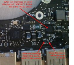
Yup. Pretty sure that is the fuse. To answer it beyond a shadow of a doubt, take you rmeter and measure resistance between the 2 legs shown below. It should be 300 kohm.
What's the resistance across the fuse showing?
So I went ahead and set my meter to 200 ohms. When I touch both sides of what we think is the fuse the meter does nothing stays at "1 ." If I touch the leads of the chip you said to check for 300kohm it stays the same as well. at "1 ."
Am I doing something wrong, please remember I know very little about electronics, if I can prove the part needs to be replaced I will have a pro do it. Thanks for the advice!
So that means the fuse is blown (i.e. "open" circuit). If you were to touch your 2 leads of your meter together it would show some low resistance. That is your reference point for what the fuse should show.
By setting the meter to 200ohms that means any resistance above 200 ohms shows an open circuit. So when you measured across those leads of the chip you need to set the range to 1Mohm or something higher than 300K. Does your meter have an auto ranging feature? You should use that if it has it.
But either way, your fuse is blown so you need to get it replaced. It is a 2 amp fuse in an 0402 package. You will want someone with good soldering skills and a microscope to do it.
Ok. So setting the meter to 20M and putting it on those leads I get "0.30". I am assuming that is good news
Ok. So setting the meter to 20M and putting it on those leads I get "0.30". I am assuming that is good newsSo I will order a fuse and find someone to replace it!
Yes. 0.3 Mega-ohms = 300 Kilo-ohms. So you are good to go. Get the fuse replaced and then tell us the good news
Yes. 0.3 Mega-ohms = 300 Kilo-ohms. So you are good to go. Get the fuse replaced and then tell us the good news
Ordered the fuse, now I got to find someone that can solder it in town. I will report back. Thanks for everything.
This works! I just fixed my 2008 15" MBP unibody's backlight. Just find that tiny little fuse (on my MPB fuse was beige with a WHITE dot located on same side as CPU/GPU so you have to take the logic board out), test it with a multimeter and if its blowing chances are that's the only problem.
I didn't even get a new fuse, I just took a soldering iron and made a connection between both sides, turning a broken fuse into a soldered connection, put my MBP back together and everything works like new. I may one day actually get a fuse and go back in and unsolder the connection and solder the new fuse back in but I don't see why I really need it. This fuse wouldn't have blown had I not unpluged the screen cable from the logic board with the battery still in my MBP (this happened when I was replacing a broken screen).
Thanks for this AMAZING thread everyone. And if anyone needs any help from me let me know, I'm willing to help. I'm so grateful for finding this thread
This works! I just fixed my 2008 15" MBP unibody's backlight. Just find that tiny little fuse (on my MPB fuse was beige with a WHITE dot located on same side as CPU/GPU so you have to take the logic board out), test it with a multimeter and if its blowing chances are that's the only problem.
I didn't even get a new fuse, I just took a soldering iron and made a connection between both sides, turning a broken fuse into a soldered connection, put my MBP back together and everything works like new. I may one day actually get a fuse and go back in and unsolder the connection and solder the new fuse back in but I don't see why I really need it. This fuse wouldn't have blown had I not unpluged the screen cable from the logic board with the battery still in my MBP (this happened when I was replacing a broken screen).
Thanks for this AMAZING thread everyone. And if anyone needs any help from me let me know, I'm willing to help. I'm so grateful for finding this thread
Congrats
I would really recommend getting a fuse on there. Although bridging the fuse "works" the purpose of a fuse is to protect more expensive and harder to fix parts. Given the number of people that spill on their Macbooks and the number of times this fuse blows you will be doing yourself a favor. Replacing one fuse vs. replacing many more parts that will fry if they are not protected.
By the way. I think the reason this fuse blows so often in a spill situation is that the WLED driver circuit is putting out over 27V (compared to most of the logic at 3.3V, 1.5V etc...). When a conductive liquid hits this circuit then really exciting things will happen if there is no fuse there.
My word of advice anyways....
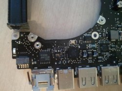
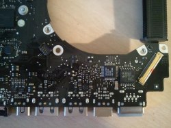
Dadioh! Same problem here. Late 2008 A1286 15.4 unibody. LED out from spill. Replaced LVDS cable, LCD display and even logic board. Still no luck. Can you look at my pics and tell me where the check points are for the components. I have access to a good multimeter and o-scope and am good at that portion of it. Bad at reading schematics though! Thanks!!!!
Danny
Danny
Attachments
I'm not exactly sure, but on your first pic on the far right side, half way down, looks like it. Can you post a more detailed pic of that area? Look for a component with 638Z marked on it with 6 legs, it's hard to see, but you can make it out with magnifyer and good light. The fuse should be near by with a white dot. Post the pic, but wait for dadioh to confirm, he's the man on this, I found mine with his detailed pics and explanations.
I found F9800. Its in the left picture, right next to L9701 (the large square inductor component on the upper right of the pic). I used the schematic posted earlier in the thread to find it. It is certainly open, so this should fix the problem. Will let you know when I get her working...
I'm not exactly sure, but on your first pic on the far right side, half way down, looks like it. Can you post a more detailed pic of that area? Look for a component with 638Z marked on it with 6 legs, it's hard to see, but you can make it out with magnifyer and good light. The fuse should be near by with a white dot. Post the pic, but wait for dadioh to confirm, he's the man on this, I found mine with his detailed pics and explanations.
Looks about right. Better high res pics would help. See my questions below.
Attachments
I found F9800. Its in the left picture, right next to L9701 (the large square inductor component on the upper right of the pic). I used the schematic posted earlier in the thread to find it. It is certainly open, so this should fix the problem. Will let you know when I get her working...
Oops. You posted while I was composing my questions. Sounds like you got it. Let us know how it goes. Quite a few success stories so far
Success! It was the blown fuse. I bypassed it for now until I can get one in. That thing is TINY, and took a lot of heat to get off. Blobbed solder across the connection and now have backlight. I don't recommend that as Dadioh has stated though. LOL. Thanks again for your help. That schematic was spot on for my machine too. New screen, 100 bucks, new LVDS cable 40 bucks, new logic board 500 bucks, most expensive soda ever! But the learning process was priceless. I now have a keyboard skin that I will NEVER take off...
Success! It was the blown fuse. I bypassed it for now until I can get one in. That thing is TINY, and took a lot of heat to get off. Blobbed solder across the connection and now have backlight. I don't recommend that as Dadioh has stated though. LOL. Thanks again for your help. That schematic was spot on for my machine too. New screen, 100 bucks, new LVDS cable 40 bucks, new logic board 500 bucks, most expensive soda ever! But the learning process was priceless. I now have a keyboard skin that I will NEVER take off...
Congrats
But I am confused. You bought a replacement logic board for $500 and it also had a blown fuse
Congrats
But I am confused. You bought a replacement logic board for $500 and it also had a blown fuse
Yes. I guess or else it blew after I installed it. I had a damaged keyboard connector (8 keys wouldn't work) and a few other damaged parts, (including the LVDS connector, or so I thought anyway) so I just went ahead and bought a new one. That fixed all my problems except the LED backlight. I figured the cable must be damaged too so I replaced that and then finally the screen. Then I found this thread!
Anyway, it's working great now. These macbooks are nice, and very slick, but VERY fragile inside. My advice to anyone working on one is to take your time, do much research, and be gentle with everything you touch....
Yup. Pretty sure that is the fuse. To answer it beyond a shadow of a doubt, take you rmeter and measure resistance between the 2 legs shown below. It should be 300 kohm.
What's the resistance across the fuse showing?
Dadioh, I read in your post to check ohms across the two legs of the component in your pic for a reading of 300 kohms. I replaced the fuse and now have continuity. What should the resistance be across the two legs shown on your pic after the fuse is replaced? Should it still be 300 kohm? Mine still reads 300 kohms. Thanks for your help, cherokee.
Dadioh, I read in your post to check ohms across the two legs of the component in your pic for a reading of 300 kohms. I replaced the fuse and now have continuity. What should the resistance be across the two legs shown on your pic after the fuse is replaced? Should it still be 300 kohm? Mine still reads 300 kohms. Thanks for your help, cherokee.
It should still be 300kohm. I only asked for that reading to be certain I was looking at the right device. Replacement of the fuse would not alter that reading. So with the fuse replaced you should be good to fire it up and bathe in the beauty of a working backlight.
So I ordered the fuses, and they were super small. I mean tiny. I ordered ones linked on this page. Anyway I wasnt able to find anyone that could solder that small. So we went ahead and blobbed some solder over the connection and turned it on. Well, that wasnt a good idea because smoke started coming from the machine. I turned it off and removed the solder and it still works like before, but i figure the journey towards having a blacklight has come to an end.  Not sure what burned up, cant seem to find anything even using a loop.
So I ordered the fuses, and they were super small. I mean tiny. I ordered ones linked on this page. Anyway I wasnt able to find anyone that could solder that small. So we went ahead and blobbed some solder over the connection and turned it on. Well, that wasnt a good idea because smoke started coming from the machine. I turned it off and removed the solder and it still works like before, but i figure the journey towards having a blacklight has come to an end.Not sure what burned up, cant seem to find anything even using a loop.
Yikes!
I have an idea for you however assuming an external display still works. I had a Macbook Pro unibody 2009 that had damaged circuit board so I could not repair the backlight. So what I did was to remove the whole LCD display and used the lower half of the Macbook as a media player attached to my TV via a miniDP to HDMI adapter. Running a freeware program called Plex which is quite a nice interface. And the MBP is still a thing of beauty mounted just below my wall mounted TV.
So there may still be light at the end of the tunnel for you (no pun intended).
Thanks to everyone for all the great info here... I'm having the same problem but on an older Macbook Pro (Early 2008 model A1260, LED backlight). This one had water spilled on it. It had been allowed to dry completely and when powered up the power light would come on but nothing else. When I opened it up the only visible damage I could find was a little corrosion on one of the parts on the Left I/O Board and I found that one of the RAM modules was bad. After a thorough cleaning and removing the bad memory the laptop powered up but the screen was dark. (You can see the image when you shine a light on and it works fine on an external monitor.)
There's a connector from the Left I/O Board to the LED driver board in the lid so I assumed that's where the power was coming from and most likely the problem. I ordered a replacement Left I/O Board off eBay and installed it, but no dice. Then I ordered a replacement LED driver board and replaced that. It still wasn't working but I did notice the backlight slightly flickering just for a second or so a couple of times, but it stopped doing that after a while and hasn't lit up at all since.
So I googled and found this thread and I was able to find the same components mentioned here on the Left I/O Board. I tested the fuse F9800 at 2000k setting and measured 00.0, so that looked good. And nearby is the component Q9806, but has the marking '530B' instead of what looks like '638Z' from the other pictures in this thread of the 17-inch unibody. Testing the two leads shown gave me 200k instead of 300k. Both the original board and the replacement board I bought measure the same so I'm assuming they're ok? Or maybe the original driver board was bad and caused the replacement I/O Board to fail in the same way?
Any ideas where to proceed from here? Does anyone have a schematic for this? Any thoughts greatly appreciated!
Thanks to everyone for all the great info here... I'm having the same problem but on an older Macbook Pro (Early 2008 model A1260, LED backlight). This one had water spilled on it. It had been allowed to dry completely and when powered up the power light would come on but nothing else. When I opened it up the only visible damage I could find was a little corrosion on one of the parts on the Left I/O Board and I found that one of the RAM modules was bad. After a thorough cleaning and removing the bad memory the laptop powered up but the screen was dark. (You can see the image when you shine a light on and it works fine on an external monitor.)
There's a connector from the Left I/O Board to the LED driver board in the lid so I assumed that's where the power was coming from and most likely the problem. I ordered a replacement Left I/O Board off eBay and installed it, but no dice. Then I ordered a replacement LED driver board and replaced that. It still wasn't working but I did notice the backlight slightly flickering just for a second or so a couple of times, but it stopped doing that after a while and hasn't lit up at all since.
So I googled and found this thread and I was able to find the same components mentioned here on the Left I/O Board. I tested the fuse F9800 at 2000k setting and measured 00.0, so that looked good. And nearby is the component Q9806, but has the marking '530B' instead of what looks like '638Z' from the other pictures in this thread of the 17-inch unibody. Testing the two leads shown gave me 200k instead of 300k. Both the original board and the replacement board I bought measure the same so I'm assuming they're ok? Or maybe the original driver board was bad and caused the replacement I/O Board to fail in the same way?
Any ideas where to proceed from here? Does anyone have a schematic for this? Any thoughts greatly appreciated!
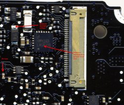
There should be a diode near the LVDS connector. On the cathode of that diode (marked with a white stripe) is the 27V that drives the LED's in the display. If you have approximately 27V there but no backlight then the issue is either the LVDS cable or the display. If there is no voltage then it is the WLED driver circuit. You want to be VERY careful probing on the board while it is running. One little slip and you will let the smoke out.
This is what the diode looks like on the 13" MBP unibody.
Attachments
I think I may have this same issue with a MBP17 (A1212). Any advice or photos of where this fuse may be on the motherboard? I removed my screen assembly and connected it to a same model MBP17 and the backlight worked...so I'm pretty sure I have eliminated the inverter, inverter cable and backlight itself.
Register on MacRumors! This sidebar will go away, and you'll see fewer ads.


