Hi all,
My 2010 27" iMac died (I killed it...) so I have switched to a different set-up involving a Mac Pro and two 20" aluminium Apple Cinema Displays which is working fairly well. Obviously these displays do not have a built-in webcam, so I have been using an old Logitech camera, but the 640x480 is very crappy and is pretty embarrassing on work calls.
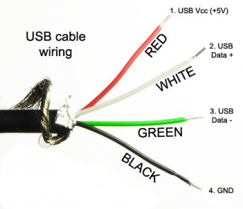
I have now stripped my dead iMac for parts, including the iSight camera. It struck me that this camera has a significantly higher 1.3MP 1280x1024 resolution - I don't suppose there is an (easy) way to turn this into an external USB camera? I have found this cable on eBay, it would this work? (I know the microphone is separate, but I don't think the mic works on my existing webcam anyway)
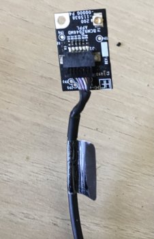
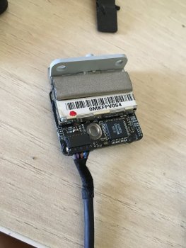
This is the camera:
.jpg")
Many thanks!
My 2010 27" iMac died (I killed it...) so I have switched to a different set-up involving a Mac Pro and two 20" aluminium Apple Cinema Displays which is working fairly well. Obviously these displays do not have a built-in webcam, so I have been using an old Logitech camera, but the 640x480 is very crappy and is pretty embarrassing on work calls.
I have now stripped my dead iMac for parts, including the iSight camera. It struck me that this camera has a significantly higher 1.3MP 1280x1024 resolution - I don't suppose there is an (easy) way to turn this into an external USB camera? I have found this cable on eBay, it would this work? (I know the microphone is separate, but I don't think the mic works on my existing webcam anyway)
This is the camera:
Many thanks!