Got a tip for us?
Let us know
Become a MacRumors Supporter for $50/year with no ads, ability to filter front page stories, and private forums.
DIY 5k Monitor - success :-)
- Thread starter fiatlux
- WikiPost WikiPost
- Start date
- Sort by reaction score
You are using an out of date browser. It may not display this or other websites correctly.
You should upgrade or use an alternative browser.
You should upgrade or use an alternative browser.
- Status
- The first post of this thread is a WikiPost and can be edited by anyone with the appropiate permissions. Your edits will be public.
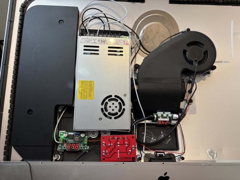
@Jack2010 The SA1 audio out connector is connected (4 wires) to the left and right red PCB (crossovers) and then each is connected to a speaker, with 4 wires for each speaker, 2 to each driver.
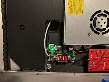
The green PCB segmented display (24.8) is reducing the 24 volts from the PSU to <12 volts to feed the PWM fan controller (which displays L.52), which controls the speed of the fan.
The green PCB segmented display (24.8) is reducing the 24 volts from the PSU to <12 volts to feed the PWM fan controller (which displays L.52), which controls the speed of the fan.
The green PCB with the segment display is not part of the audio connection. It is a step down voltage converter that I used to convert 24Vdc to 12Vdc to run the iMac case fan (I don't know if there is a suitable 12Vdc source on the SA1 and since I had an extra converter I simply used it).Thx for sharing and just be sure I understand it properly: SA1 is connected to this red PCB (crossover) and than is connected to green PCB with segment display (what is this?) that is than connected to speakers?
For the audio connection, only two steps:
1. SA1 is connected to the two red PCB crossovers (YLY-2088), one crossover for the right speaker and one for the left.
2. The crossovers are then connected directly to the speakers, two lines for the tweeter and two lines for the woofer.
(Note - I had to add extensions to the right speaker wires to reach the crossover)
Hope that helps!
@PaulD-UK - You have definitely been around a long time to put that together without having any other info!! 😀😁🤣@Jack2010 The SA1 audio out connector is connected (4 wires) to the left and right red PCB (crossovers) and then each is connected to a speaker, with 4 wires for each speaker, 2 to each driver.
The green PCB segmented display (24.8) is reducing the 24 volts from the PSU to <12 volts to feed the PWM fan controller (which displays L.52), which controls the speed of the fan.
The "L.52" is actually "25.7"... Specifically, 25.7 degrees C for the temperature sensor. It was easier to install the PWM board upside down for wiring purposes... LOL
SubDriver’s 27 inch 2017 iMac Conversion to a Standalone 5K Display
For my conversion, I ultimately chose a relatively non-complex end state. Below are some of the decision-making considerations I went through for my conversion.
“Big Picture” Considerations:
1. I ultimately chose a relatively non-complex end state – retain the functionality of the display, the speakers, and the iMac case fan.
2. I wanted to minimize the number of cords coming out the rear of the case, so this meant re-using the power plug connector and selecting a board that supported 5K/10-bit over USB-C.
3. I wanted to have options should I choose to upgrade or add components in the future (e.g., adding a USB webcam if I find I don’t like using the Continuity Camera functionality of my iPhone).
Detailed Plans and Considerations
Power Supply Selection – I was initially planning to try to re-use the iMac power supply but I also knew I wanted to use either the JRY--SA1 board or the R1811 board, both of which operate best with 24 Vdc (plus I wanted the USB C option). Ultimately, I elected to get a standalone 24 Vdc power supply. Options and considerations for how to power it is essentially a trade off as detailed below.
1. Use the original iMac 12 Vdc PSU and use a boost converter capable of handling at least 8-10 amps at 24 Vdc to provide power to the driver board.
2. Buy a new PSU to deliver 24Vdc and at least 8-10 amps to ensure I could achieve everything I wanted and leave some room for potential future growth.
Notes about the LRS-350-24 vs LRS-200-24 power supplies
1. Both are the same size (each will fit behind the display)
2. Both are essentially the same price (within ~$2US)
3. I wanted the flexibility of the additional power from the LRS-350 vs the LRS-200
4. I couldn’t find an LRS-300 or LRS-250 for a reasonable price… it is possible they may be getting discontinued because I could not find many sellers and the Mean Well website doesn’t list them as options (skips from LRS-200 to LRS-350)
5. The fan on my LRS-350 unit would come on within about a minute of powering up the display, which seemed early (setpoint is supposedly 50 deg C) – it possible my unit has a defective temperature sensor
6. The fan on the LRS-350 only has one speed and it is LOUD
7. Ultimately, since I was planning on re-using the iMac case fan I simply disconnected the LRS-350 fan
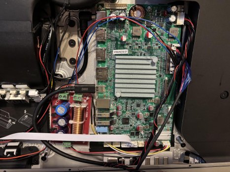
LCD Driver Board Selection – I quickly narrowed my options down to the R1811 and JRY-SA1 because they are the only boards that have USB C connectivity AND deliver 5K/60Hz/10bit across all video input sources. I selected the JRY-SA1 over the R1811 for the following reasons:
1. The SA1 is less expensive (~$195US vs ~$295US)
2. The SA1 doesn’t require a fan for cooling
3. Audio amplifier power wasn’t much of a concern
4. I don’t have much need to be diving deeply into the on screen menu options to manipulate display and other board settings – the R1811 settings menu is far superior to the SA1, but I don’t use it often enough to make it a meaningful difference for my use case. This also means I don’t need the IR capability of the R1811 to frequently manipulate the menu.
5. The USB 3.0 ports on the SA1 might allow for additional growth/capability that the USB 2.0 ports on the R1811 won’t.
Audio Considerations – Maintaining the functionality of the iMac speakers has definite benefits and drawbacks
1. For internal computer speakers, they are very capable and high quality with separate leads for the tweeters and woofers.
2. The speaker casings are LARGE and take up valuable space inside the iMac case.
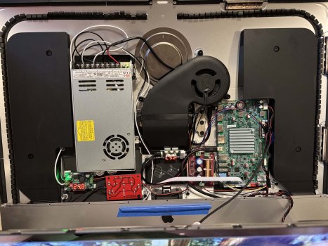
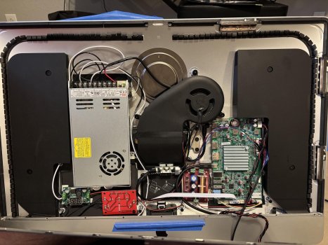
Mounting the Components
1. Layout your components ahead of time to simulate how and where you will mount each item in the iMac case. Care must be taken to prevent your components from contacting metal parts of the iMac case and causing a short.
2. To provide the ability to arrange the components in the locations I wanted, I removed several of the mounting posts using a set of pliers and snapping them off. This was easier than I initially thought it would be.
3. Where possible, I used the existing screw mounts to support the components. I used one of these for one of the crossover boards and also to help with the power supply.
4. For the power supply specifically:
5. Plastic standoff mounts and super glue do an excellent job of mounting the boards and holding them securely in place. Make sure you get super glue that is suitable for metal and plastic.
Heat Considerations
1. Depending on your use case, you may not need an exhaust fan for the iMac case.
2. If you are concerned about heat buildup, the only exhaust path for hot air are the vents in the center of the back side of the iMac case. Since these vents are not near the top of the case the amount of natural circulation will be limited. Thus, a fan of some sort should be used to pull the hot air out through the vents.
3. The original iMac fan is well suited for this by being located relatively high in the case and getting ducted directly to the vents. For the piece of ducting that directs air out the vents, I removed the copper heat sink tubing simply by bending it back and forth until it snapped – very easy to do. This preserves a properly fitting piece of duct at a critical location to ensure air from the fan is routed out of the iMac case.
4. The iMac fan operates on 12 Vdc and requires a PWM signal to control its speed. I recommend getting a PWM that has a temperature sensor included to allow you to set the fan to turn on and off at your desired temperatures while also varying the fan’s speed across an acceptable temperature range to balance cooling and noise (the iMac fan is VERY quiet are low speeds by the way)
5. Using the original iMac fan does use a significant amount of space. Other solutions are certainly possible.
Note: Using some of the components below will require soldering in some cases, but it is not overly complex.
1. My soldering skills are not good, but they were adequate for the amount of soldering for this conversion
2. It may be possible to do this conversion without soldering, but you will need to find some different components than some of those that I used (e.g., using wire nuts or screw type wire connectors on PCBs)

********* This section has not yet been accomplished **************************************
Future Modification Preview – I am going to attempt to re-use the 128GB Fusion Drive SSD from my iMac as detailed below. I will update the post after I get a chance to try it out.
Re-use of the iMac’s Fusion Drive SSD – My 2017 iMac used a 128GB “12+16” pin SSD for its fusion drive.
1. I didn’t want to simply pitch this valuable item but the 12+16 pin configuration is pretty much only used by Apple and I didn’t want to spend $50+ to purchase a suitable external enclosure to use it as an external drive.
2. I'm planning to use the following components to mount it internally and connect it to one of the USB A ports on the SA1 board.
Will let you all know how it goes….
***********************************************************************************
For my conversion, I ultimately chose a relatively non-complex end state. Below are some of the decision-making considerations I went through for my conversion.
“Big Picture” Considerations:
1. I ultimately chose a relatively non-complex end state – retain the functionality of the display, the speakers, and the iMac case fan.
2. I wanted to minimize the number of cords coming out the rear of the case, so this meant re-using the power plug connector and selecting a board that supported 5K/10-bit over USB-C.
3. I wanted to have options should I choose to upgrade or add components in the future (e.g., adding a USB webcam if I find I don’t like using the Continuity Camera functionality of my iPhone).
Detailed Plans and Considerations
Power Supply Selection – I was initially planning to try to re-use the iMac power supply but I also knew I wanted to use either the JRY--SA1 board or the R1811 board, both of which operate best with 24 Vdc (plus I wanted the USB C option). Ultimately, I elected to get a standalone 24 Vdc power supply. Options and considerations for how to power it is essentially a trade off as detailed below.
1. Use the original iMac 12 Vdc PSU and use a boost converter capable of handling at least 8-10 amps at 24 Vdc to provide power to the driver board.
a. The converters I could find are typically used in applications such as golf carts (example: Boost Converter) (~$20US)
b. If you don’t want the option of using the USB C port for power delivery, there are smaller converters that will support 5-6 amps at 24 Vdc
c. For boost converters to deliver the amps desired, converter input should be larger than the output current. For example, to output 3A you should input 5-6A, otherwise it will not achieve the effect you want. This means the amperage input from the iMac PSU would need to be ~14-15 amps to deliver an output of 8-10 amps. Although the iMac PSU is rated for that amount of power (12Vdc x 15A = 180Watts), it would mean the PSU would be consuming more power and generating a lot more heat than I wanted just to power the driver board.
d. I could not come up with a decent location to easily mount the converter because it is 1.3 inches (33mm) tall
e. I was worried about dissipating heat from both the PSU and the boost converter
2. Buy a new PSU to deliver 24Vdc and at least 8-10 amps to ensure I could achieve everything I wanted and leave some room for potential future growth.
a. The Mean Well LRS series of power supplies are well suited to provide the power needs and flexibility (e.g., multiple taps for power) I was looking for
b. However, they are LARGE and BARELY thin enough to fit in the iMac case with the display installed.
c. They also aren’t easily mounted inside the case
d. The fact others had done their conversions with these LRS power supplies ultimately gave me the confidence to go with the LRS-350-24
Notes about the LRS-350-24 vs LRS-200-24 power supplies
1. Both are the same size (each will fit behind the display)
2. Both are essentially the same price (within ~$2US)
3. I wanted the flexibility of the additional power from the LRS-350 vs the LRS-200
4. I couldn’t find an LRS-300 or LRS-250 for a reasonable price… it is possible they may be getting discontinued because I could not find many sellers and the Mean Well website doesn’t list them as options (skips from LRS-200 to LRS-350)
5. The fan on my LRS-350 unit would come on within about a minute of powering up the display, which seemed early (setpoint is supposedly 50 deg C) – it possible my unit has a defective temperature sensor
6. The fan on the LRS-350 only has one speed and it is LOUD
7. Ultimately, since I was planning on re-using the iMac case fan I simply disconnected the LRS-350 fan
LCD Driver Board Selection – I quickly narrowed my options down to the R1811 and JRY-SA1 because they are the only boards that have USB C connectivity AND deliver 5K/60Hz/10bit across all video input sources. I selected the JRY-SA1 over the R1811 for the following reasons:
1. The SA1 is less expensive (~$195US vs ~$295US)
2. The SA1 doesn’t require a fan for cooling
3. Audio amplifier power wasn’t much of a concern
4. I don’t have much need to be diving deeply into the on screen menu options to manipulate display and other board settings – the R1811 settings menu is far superior to the SA1, but I don’t use it often enough to make it a meaningful difference for my use case. This also means I don’t need the IR capability of the R1811 to frequently manipulate the menu.
5. The USB 3.0 ports on the SA1 might allow for additional growth/capability that the USB 2.0 ports on the R1811 won’t.
Audio Considerations – Maintaining the functionality of the iMac speakers has definite benefits and drawbacks
1. For internal computer speakers, they are very capable and high quality with separate leads for the tweeters and woofers.
a. However, this also necessitates using some form of crossovers from the driver board in order to split out the treble and bass signals appropriately for the tweeter and woofer.
b. The iMac speakers have a 4 ohm impedance – you need to ensure your crossovers will match this impedance value.
c. I recommend obtaining crossovers that have some means of adjustability (e.g., jumpers) to help you attain the best overall sound to suit your preferences.
d. Ensure the physical size of the crossovers you select will allow them to be mounted in your desired location – components on some boards are tall and will limit your mounting location options.
2. The speaker casings are LARGE and take up valuable space inside the iMac case.
Mounting the Components
1. Layout your components ahead of time to simulate how and where you will mount each item in the iMac case. Care must be taken to prevent your components from contacting metal parts of the iMac case and causing a short.
2. To provide the ability to arrange the components in the locations I wanted, I removed several of the mounting posts using a set of pliers and snapping them off. This was easier than I initially thought it would be.
3. Where possible, I used the existing screw mounts to support the components. I used one of these for one of the crossover boards and also to help with the power supply.
4. For the power supply specifically:
a. I used two of the mounts that I snapped off to support its weight at the bottom by super gluing mounts to the case and resting the power supply on them (you can see them between the crossover board and the power supply case).
b. I used 2 tie wraps which run through the upper portion of the side of the power supply enclosure and wrapped them around the screw post that was originally used as one of the hard drive supports.
5. Plastic standoff mounts and super glue do an excellent job of mounting the boards and holding them securely in place. Make sure you get super glue that is suitable for metal and plastic.
Heat Considerations
1. Depending on your use case, you may not need an exhaust fan for the iMac case.
2. If you are concerned about heat buildup, the only exhaust path for hot air are the vents in the center of the back side of the iMac case. Since these vents are not near the top of the case the amount of natural circulation will be limited. Thus, a fan of some sort should be used to pull the hot air out through the vents.
3. The original iMac fan is well suited for this by being located relatively high in the case and getting ducted directly to the vents. For the piece of ducting that directs air out the vents, I removed the copper heat sink tubing simply by bending it back and forth until it snapped – very easy to do. This preserves a properly fitting piece of duct at a critical location to ensure air from the fan is routed out of the iMac case.
4. The iMac fan operates on 12 Vdc and requires a PWM signal to control its speed. I recommend getting a PWM that has a temperature sensor included to allow you to set the fan to turn on and off at your desired temperatures while also varying the fan’s speed across an acceptable temperature range to balance cooling and noise (the iMac fan is VERY quiet are low speeds by the way)
5. Using the original iMac fan does use a significant amount of space. Other solutions are certainly possible.
Required Parts (Links below are the components I used, but others may also be suitable)Note: Using some of the components below will require soldering in some cases, but it is not overly complex.
1. My soldering skills are not good, but they were adequate for the amount of soldering for this conversion
2. It may be possible to do this conversion without soldering, but you will need to find some different components than some of those that I used (e.g., using wire nuts or screw type wire connectors on PCBs)
- LCD driver board – the main sources for these are StoneTaskin.com, eBay, and AliExpress. Ensure you know your specific display model and version before you purchase your board
- Power supply
- Step down voltage converter (to supply 12 Vdc to the PWM board for the iMac case fan)
- PWM board for the iMac fan – controls fan speed based on temperature
- Crossover boards for speaker functionality (these are large in size probably overkill given their 400W rating, but they were not expensive, they have jumpers that allow manipulating the sound output for both bass and treble, and the wiring connectors are easy – if space were a concern, I would probably try to find something smaller in size)
- 90 Degree DC Power Pigtails to connect the power supply to the LCD driver board (ensure you get the right internal size barrel for your board – 2.1 mm or 2.5 mm [most are 2.5mm AFAIK])
- Plastic standoff mounts with adhesive
- Super glue suitable for metal to improve the adhesion of the standoff mounts when mounting them to the iMac case
- Exhaust fan ducting – I bought this in order to fully preserve the integrity my iMac’s old motherboard for selling on eBay later
- Electrical tape / Kapton tape
********* This section has not yet been accomplished **************************************
Future Modification Preview – I am going to attempt to re-use the 128GB Fusion Drive SSD from my iMac as detailed below. I will update the post after I get a chance to try it out.
Re-use of the iMac’s Fusion Drive SSD – My 2017 iMac used a 128GB “12+16” pin SSD for its fusion drive.
1. I didn’t want to simply pitch this valuable item but the 12+16 pin configuration is pretty much only used by Apple and I didn’t want to spend $50+ to purchase a suitable external enclosure to use it as an external drive.
2. I'm planning to use the following components to mount it internally and connect it to one of the USB A ports on the SA1 board.
a. A 12+16 pin to NVME M.2 M-key converter (~$9US)
b. A NVME M.2 M-key to USB 3.0 converter (~$10US)
Will let you all know how it goes….
***********************************************************************************
Attachments
-
 iMac Case with posts removed.jpg385.8 KB · Views: 164
 -
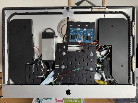
 PSU-Crossover-Converter-PWM-Fan.jpg513.3 KB · Views: 165
 -
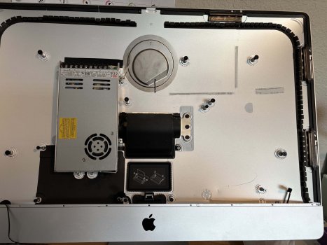 iMac with LRS PSU.jpg491.2 KB · Views: 169
 -
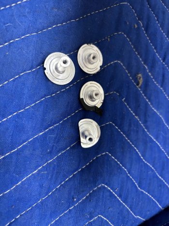 iMac posts after removal.jpg624 KB · Views: 176
 -
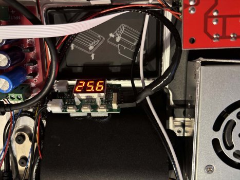 Final-Close-up PWM-On.jpg466.1 KB · Views: 149
 -
 Final-Close-up Converter-On.jpg531.3 KB · Views: 191
 -
 Final-1-on.jpg546.8 KB · Views: 203
 -
 Final-1.jpg550.9 KB · Views: 192
 -
 Final-Close-up Right.jpg662.6 KB · Views: 179
Last edited:
As an Amazon Associate, MacRumors earns a commission from qualifying purchases made through links in this post.
Great insights (especially that I am just ahead of similar build) and speaking of power supply requirements... don't you think 350W at 24V is a bit overkill for the actual needs? I mean they are selling this board with 5A PS, so 120W (assuming it's spec is real)... for my own project I was thinking about something in the range of 150-170W (6-7A) just to be on the safe side (90W "reserved" for USB-C PD when needed and 60-80W for the board, screen, USB peripherals, power losses, etc. which seems to be a lot already). What do you think?
@Jack2010 ”...for my own project I was thinking about something in the range of 150-170W (6-7A) just to be on the safe side (90W "reserved" for USB-C PD when needed and 60-80W for the board, screen, USB peripherals, power losses, etc. which seems to be a lot already). What do you think?”
That should be fine.
Other posters have shown that the amount of power available for laptop charging is increased with a higher power PSU, but your estimates seem OK.
No one has confirmed the exact input/output charging figures, so if you don’t need the highest charging rates it’s safe not to use too big a PSU.
Last edited:
My build is ready and working flawlessly but 2 MEMS microphones still record voices from speakers during video conference so other side hears their own voices. I did smallest hole I could and also insulate them by hot glue gun and also with some wool but still, echo on the other side is still there. I think only option is to buy USB camera with microphone.
If anyone finish conversion including speakers with working microphones without echo on the other side I would appreciate details.
If anyone finish conversion including speakers with working microphones without echo on the other side I would appreciate details.
Attachments
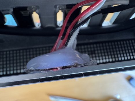

Quick and dirty picture of my quick and dirty solder job.I use the original button, it does not have any mystery, follow the clues of the button to the two cables, one is the common one and the other the ON/OFF and you connect to the cable that goes to the original button.")
The red wires are soldered to the two original wires connected to the power button (as the original wires were not long enough)
Mistakes I made (and will be correcting once I take the time to revisit the project):What are you changing in regards to the sound and what will you be doing with the mouse and keyboard?
I think you convinced me. What crossovers should I get?
- Hooked the sound up to the headphone out instead of using the onboard audio
- Used the wrong crossover (wrong impedance I think); I now got the ones recommendeb by PaulD-UK
- Didn't use additional capacitor and inductor; got these now too and have to solder them in-line
- One of the speakers is hooked up the wrong way: tweeter to crossover boards bass and vice versa as well as with inverted polarity. As I don't know now which one it is, I'll have to figure that out too; this is going to be sooo fun!
How is your screeen connected (HDMI, DP or USB-C) and to what computer( PC, MacBook, macMini, etc.)? Mine is connected over USB-C to a MacMini M4. I ordered the board end of March and would therefore assume that we have the same Firmware.I also have the SA1. My status light changes to red when it goes to sleep and I am able to wake the computer and have the screen automatically come back on (MBP). It takes a few seconds. So probably a firmware update is needed. I purchased mine in March.
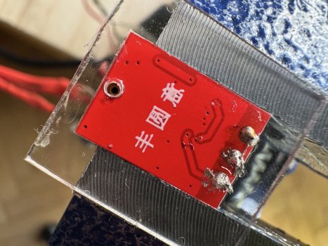
1 and 2 are already connected as are 3 and 4. Therefore: one wire from the power button goes to either 1 or 2, the other to either 3 or 4. My photo from the post above should help to clarify.Also, could you help me with the original power button setup? Which contact points should I solder the wires to? See the photo and let me know the numbers. ie. 1 and 4.
@SubDriver "Future Modification Preview – I am going to attempt to re-use the 128GB Fusion Drive SSD...
...I'm planning to... connect it to one of the USB A ports on the SA1 board."
As far as has been so far determined, the USB-A ports on the SA1 are only USB 3.x when you connect the USB-B input with it's own cable to a USB 3.x (or TB4) output port on the Mac.
If you are just running the SA1 using it's USB-C video input, then there is only enough bandwidth for the USB-A output ports on the SA1 to operate at USB 2 480Mbps speeds.
Whilst I'm not 100% sure of this, it remains to be determined in practice as to how much of the USB-C cable's bandwidth the SA1 is using - and how the SA1's USB-C and USB-A/B ports are interconnected through the onboard hub.
Link:
"USB-C with DP Alt mode has 2 modes:
And I think 5K/60 is using the similar bandwidth...
...I'm planning to... connect it to one of the USB A ports on the SA1 board."
As far as has been so far determined, the USB-A ports on the SA1 are only USB 3.x when you connect the USB-B input with it's own cable to a USB 3.x (or TB4) output port on the Mac.
If you are just running the SA1 using it's USB-C video input, then there is only enough bandwidth for the USB-A output ports on the SA1 to operate at USB 2 480Mbps speeds.
Whilst I'm not 100% sure of this, it remains to be determined in practice as to how much of the USB-C cable's bandwidth the SA1 is using - and how the SA1's USB-C and USB-A/B ports are interconnected through the onboard hub.
Link:
"USB-C with DP Alt mode has 2 modes:
- allocate 2 of the 4 total high speed wire pairs to a "half" DP connection, the other 2 wire pairs remain available for USB3 (so up to 10G)
- allocate all 4 wire pairs for a full DP connection, same total bandwidth as a regular DP port with the same speed (which for DP are RBR, HBR1, HBR2, HBR3 currently). Only have USB2 available simultaneously."
And I think 5K/60 is using the similar bandwidth...
Last edited:
Not that I know it for sure but I think there is a piece of software making sure there is no echo/ coupling.If anyone finish conversion including speakers with working microphones without echo on the other side I would appreciate details.
There is a need to filter some frequencies and so some sort of sound processing is needed in order to cut some frequencies to avoid coupling. As for the echo possibly some "sound management" app can be helpful in your case.
Without any of these you cen test on what speakers volume level the echo is gone by lowering it untill there is no echo effect. But I am afraid it will be very low/ quiet...
The internal USB webcam is connected to one of the USB-A ports or the board. I will be attaching a 4-port USB-A hub (USB 3) with ~20cm cable to the boards other USB-A port, lead that cable out through the RAM door and attach it (the hub) to the back of the screen (with double sided tape); not pretty but easy. Keyboard and Mouse connect there but I won't be using it for HDs or SSDs; these all go directly into the MacMini.What are you changing in regards to the sound and what will you be doing with the mouse and keyboard?
The monitor is connected to the Mac via USB C which should be plenty fast for image/sound (in) and webcam/keyboard/mouse (out). Only one cable between screen and macMini...
the back of the screen will not be very pretty:
- power going in through the original power cable/connection
- RAM-door is installed with a big rubber grommet:
- USB-C goes in
- OSD cables go out; OSD board is glued to back with double sided tape
- cable for USB-A hub goes out; hub is glued to back with double sided tape
- Mouse connects to keyboard; keyboard connects to hub. No, I don't have a BT keyboard/mouse combo (yet)
Also, am considering to 3D print Xarli's RAM door that allows for the installation of the OSD board inside the RAM door.
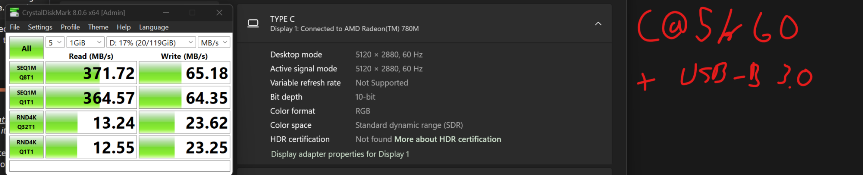
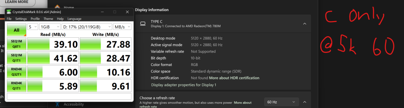
I confirm about usb bandwidth:@SubDriver "Future Modification Preview – I am going to attempt to re-use the 128GB Fusion Drive SSD...
...I'm planning to... connect it to one of the USB A ports on the SA1 board."
As far as has been so far determined, the USB-A ports on the SA1 are only USB 3.x when you connect the USB-B input with it's own cable to a USB 3.x (or TB4) output port on the Mac.
If you are just running the SA1 using it's USB-C video input, then there is only enough bandwidth for the USB-A output ports on the SA1 to operate at USB 2 480Mbps speeds.
Whilst I'm not 100% sure of this, it remains to be determined in practice as to how much of the USB-C cable's bandwidth the SA1 is using - and how the SA1's USB-C and USB-A/B ports are interconnected through the onboard hub.
Link:
"USB-C with DP Alt mode has 2 modes:
On the Chinese 4K/144Hz monitor that uses the SA1, the USB-B input port on the SA1 has to receive a signal for the USB-A USB 3.x ports to be active.
- allocate 2 of the 4 total high speed wire pairs to a "half" DP connection, the other 2 wire pairs remain available for USB3 (so up to 10G)
- allocate all 4 wire pairs for a full DP connection, same total bandwidth as a regular DP port with the same speed (which for DP are RBR, HBR1, HBR2, HBR3 currently). Only have USB2 available simultaneously."
And I think 5K/60 is using the similar bandwidth...
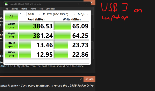
I used a USB 3.0 thumbdrive with crystal diskmark:
Attachments
It is overkill, but the only other LRS option available cheaply (at least in the US) was the LRS-200. I think the sweet spot would be an LRS-250 since that would get u 10+ amps at 24 volts and would likely be enough to cover powering the screen, power delivery over USB-C, and any other components that would need power. Unfortunately, MeanWell no longer produces an LRS-250 or LRS-300. So I went with the LRS-350 to ensure I had sufficient power to cover any future possible expansion of capabilities.Great insights (especially that I am just ahead of similar build) and speaking of power supply requirements... don't you think 350W at 24V is a bit overkill for the actual needs? I mean they are selling this board with 5A PS, so 120W (assuming it's spec is real)... for my own project I was thinking about something in the range of 150-170W (6-7A) just to be on the safe side (90W "reserved" for USB-C PD when needed and 60-80W for the board, screen, USB peripherals, power losses, etc. which seems to be a lot already). What do you think?
PaulD - I recall what you mention above about the USB-B vs USB-C ports. That is partly why I want to give it a try - would like to get some sort of definitive answer about the USB 3.0 capability of the SA1 for our conversion purposes.@SubDriver "Future Modification Preview – I am going to attempt to re-use the 128GB Fusion Drive SSD...
...I'm planning to... connect it to one of the USB A ports on the SA1 board."
As far as has been so far determined, the USB-A ports on the SA1 are only USB 3.x when you connect the USB-B input with it's own cable to a USB 3.x (or TB4) output port on the Mac.
If you are just running the SA1 using it's USB-C video input, then there is only enough bandwidth for the USB-A output ports on the SA1 to operate at USB 2 480Mbps speeds.
Whilst I'm not 100% sure of this, it remains to be determined in practice as to how much of the USB-C cable's bandwidth the SA1 is using - and how the SA1's USB-C and USB-A/B ports are interconnected through the onboard hub.
Link:
"USB-C with DP Alt mode has 2 modes:
On the Chinese 4K/144Hz monitor that uses the SA1, the USB-B input port on the SA1 has to receive a signal for the USB-A USB 3.x ports to be active.
- allocate 2 of the 4 total high speed wire pairs to a "half" DP connection, the other 2 wire pairs remain available for USB3 (so up to 10G)
- allocate all 4 wire pairs for a full DP connection, same total bandwidth as a regular DP port with the same speed (which for DP are RBR, HBR1, HBR2, HBR3 currently). Only have USB2 available simultaneously."
And I think 5K/60 is using the similar bandwidth...
Hoping to get time to test it out this weekend if my parts get delivered by then.
Thanks! Will let you know if I get different resultsI confirm about usb bandwidth:
I used a USB 3.0 thumbdrive with crystal diskmark:
Thanks for the hint. I never experienced such behavior.Not that I know it for sure but I think there is a piece of software making sure there is no echo/ coupling.
There is a need to filter some frequencies and so some sort of sound processing is needed in order to cut some frequencies to avoid coupling. As for the echo possibly some "sound management" app can be helpful in your case.
Without any of these you cen test on what speakers volume level the echo is gone by lowering it untill there is no echo effect. But I am afraid it will be very low/ quiet...
I just borrowed Dell Pro Webcam WB5023 (USB webcam) and the echo is still there. The other side can clearly hear own words after like 1s of saying them. Because I disconnected USB sound card with MEMS microphones, it's definitely not issue with them.
Could it be issue with speakers somehow? I am using 10uF audio capacitors (polypropylene) and 0.15 milliHenry air-cored inductors for both of them (@PaulD-UK I finally got them
) but I doubt it could result in this.EDIT: On the right side, yellow is USB sound card disconnected and on top internal camera disconnected.
Attachments
@jorycz That's the reason that people use headphones or AirPods when talking live to someone else with a computer link-up.
And YouTube creators use in-vision close microphones to make their voice as separate as possible from any background noise.
Apple can allow it with their laptops and phones because they use software to isolate the sound so no feedback between mic and speakers occurs.
I don't know any software app that can do the same thing, because the software has to be integrated with the hardware.
Connected to USB hub (you can see it on the right side in my photo) which is connected to USB2 port of R1811 driver board.Dell Pro Webcam WB5023: is it connected to te Mac or to the SA1?
Every cheap laptop can do that but I understand that it should have support on HW level so something is aware that particular sound mic is recording came from speakers and so "do not forward it" ...@jorycz That's the reason that people use headphones or AirPods when talking live to someone else with a computer link-up.
And YouTube creators use in-vision close microphones to make their voice as separate as possible from any background noise.
Apple can allow it with their laptops and phones because they use software to isolate the sound so no feedback between mic and speakers occurs.
I don't know any software app that can do the same thing, because the software has to be integrated with the hardware.
It seems to me that no one is using microphone and speakers after conversion for video conference like before in original iMac.
TBH I didn't think that it could be issue. I still can't accept the idea of using headphones during video calls at home
I just wanna add that I have been using the LRS-150-24 in both of my 5k conversions, they work just fine. Granted, my laptop only really reads max charging speed around 60w. I have a usb power tester, I can get more accurate readings soon.It is overkill, but the only other LRS option available cheaply (at least in the US) was the LRS-200. I think the sweet spot would be an LRS-250 since that would get u 10+ amps at 24 volts and would likely be enough to cover powering the screen, power delivery over USB-C, and any other components that would need power. Unfortunately, MeanWell no longer produces an LRS-250 or LRS-300. So I went with the LRS-350 to ensure I had sufficient power to cover any future possible expansion of capabilities.
Register on MacRumors! This sidebar will go away, and you'll see fewer ads.