Become a MacRumors Supporter for $50/year with no ads, ability to filter front page stories, and private forums.
Status
The first post of this thread is a WikiPost and can be edited by anyone with the appropiate permissions. Your edits will be public.
Haijing only list the T95MV/SG95MW_2UBTPH_U001 for 27" and 32" UHD screens, so they would have to be asked if there is 21" iMac 4096x2304 firmware available.

StoneTaskin list the CY.R9516 for the iMac 2015 4K, but no mention of the 2017+ SD (B1) panels:
  • 2015 - Apple P/N 661-02990, Display ID - LM215UH1 (SD)(A1)
And the CY.R9513 is listed for both 2015 and 2017+ panels.

Apparently the 2015 and 2017+ iMac 4K models have different eDP cable pin-counts?
 
Last edited:
They are 4K only. I thought you collect 4K boards as well. Reading the thread i noticed that many people discussed converted 4K iMacs here, so those boards could be useful. Sure you can remove those boards if you feel that they don't belong here.
@shijan You make a fair point. I added a 4K statement above the table and added some color and words to ensure it is easy to note those boards are 4K only.
 
@SubDriver @shijan It seems like the R9513 is the preferred choice for 21" 4K iMacs, so maybe that is the one that should be listed in the table (or both?).
StoneTaskin only mention LG's own monitor 21" 4K screen panel in their tested compatible list.
 
Hi! Last update of my iMAC 21.5 4K retina conversion. Epic failure so far! :)
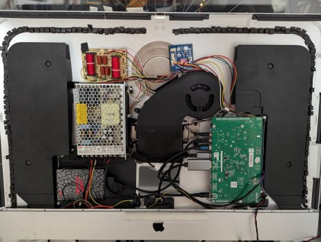
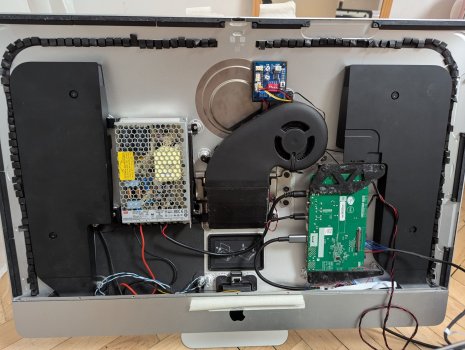
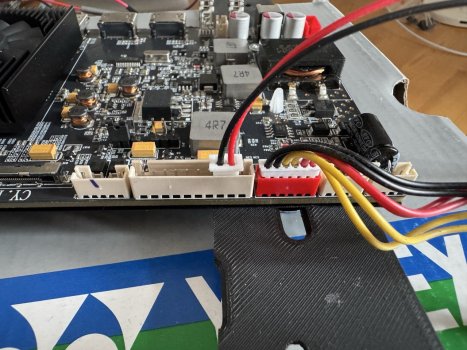
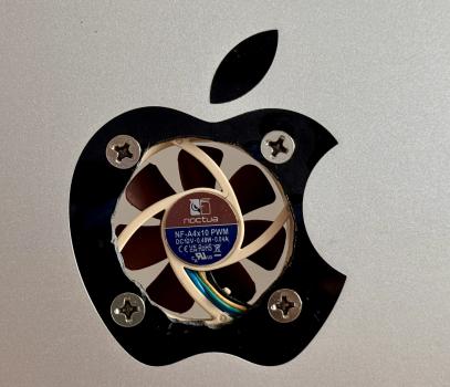
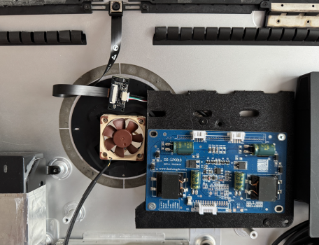
Have used the R9513 v5 board. 12v 60W powerboard. 12v PWM fan contoller, heatcontrolled.
1st board got in contact with casing and shorted. Got a second board. Added capacitor as highpass filter for tweaters.
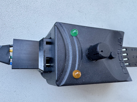
Tried to extend the LED, and IR sensor by desoldering from controlstrip. Burnt controlstrip. Got new board and strip.
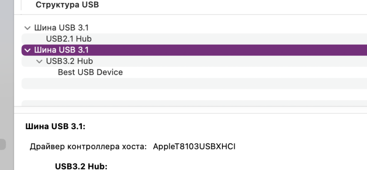
Got a webcam. Very long USB-A cable. Strangely enough 5wires. Cut the cable and shorted it. Camera stopped working.
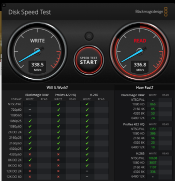
Installed a prefab. internal hub to connect camera and SSD harddrive.
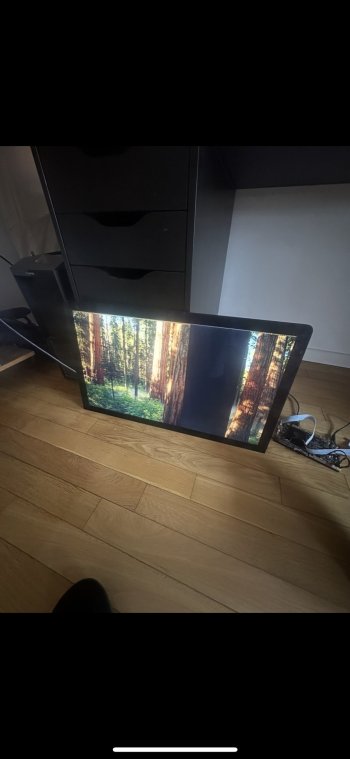
Installed new displayboard, padding the back of the casing with electric tape to not shortcircuit again. New controlstrip, soldered IR extension and soldered on cables from original powerswitch. Worked sort of....
Everytime i raised from chair the screen blanked. Removed the internal USB-hub and SSD. Problem solved. But the IR sensor only intermittently working. When holding hands on extensioncables it works, when removing, stop working. Better shielding? Covered the cables in aluminum foil. Bad idea. Screen went blank and board not working anymore :)
Now only getting "no connection" when starting up. No matter if DP or HDMI.
Unsure what happend with the extended IR sensor, but some sort of shortcircuit again.
Amazed how sensitive these things are!
Was quite upset for a while, but now have diseded for a final go, and to order a third board!

Will now skip internal hub for SSD.
Try only very short IR-sensor extension, to just get it out of the casing.

Question:
Any idea what have happened this time? Can the controlstrip shortcircuit the whole displayboard? (I guess it can...)
Does anyone know what type of IR sensor is fitted on the controlstrip?

Is this the record for conversionfailures (Ordering 3rd board :))?
 
@Mowgli10L Bad luck, sorry... 😶
I guess looking at Vishay's catalogue that the IR diode is something like a TSOP4438, or TSOP14638.
It seems to be a 'Mold' 6mm receiver at 38MHz, centre pin GND, and with an AGC of 2, 4 or 6. Maybe 6?

But you can get a spare Control Strip from StoneTaskin, which is a more certain solution...

Intermittent shut-downs, like getting up from a chair, is static electricity in bad unshielded cables, usually a HDMI cable, but could be anything else.
 
Last edited:
So i ordered JRY-W9RQUHD-FA1 from GIVIFENI Store for surprisingly low cost $102.82. Will let you know in about two weeks if it is fake or real deal.
By the way, i noticed that many boards on Ali don't use real board name and so it excluded from normal search. So you need to look for them manually in seller's catalog.

By the way this board costs $72 if order 1000 pieces https://www.globalsources.com/LCD-controller/ps5-controller-1201121201p.htm
Key Specifications/ Special Features:
JRY-W9RQUHD-FA1 board is a UHD display driver board with built-in MPRT dimming function and maximum resolution
support OD, MPRT, lock dimming , freesync , HDR, HDCP, EDID and so on ,
3840X2160/165Hz.
Support eDP screen interface signal output.
Supports multiple OSD languages to choose from.
Support online software updates on the motherboard.
Supports HDMI 2.0 and HDCP 2.3 versions.
Supports DP1.4 signal input.
Supports headphone and speaker functions.
Supports OD acceleration function.
Supports Freesync functionality.
Supports HDR function
 
Last edited:
I confirm about usb bandwidth:
I used a USB 3.0 thumbdrive with crystal diskmark:
@PaulD-UK I can confirm that my combination of adapters for the left over 128GB Fusion Drive SSD functions properly when connected directly to my Mac Studio and via a hub to the Mac Studio. I was worried that going through converters wouldn't allow it to function properly. The conversion does slow it down by about 50 MB/sec, (I get about 430 MB/sec with my external 1TB WD SSDs and I get about 380 MB/sec using the 12+16 pin to M.2 NVME converter connected to the NVME to USB 3.0 converter) - See pics below. Total cost for the 2 adapters was $18 US.
iMac SSD to M-Key NVME adapter
M-Key NVME to USB 3.0 adapter

Gonna test it out connected to the driver board next weekend when I open the iMac case.


SSD Adapter - Top.jpeg


SSD Adapter - Side.jpeg


Default 128GB SSD - Anker Hub.png
 
Last edited:
As an Amazon Associate, MacRumors earns a commission from qualifying purchases made through links in this post.
Hello. Update, JRY-W9RQUHD-aa1 replaced with JRY-W9RQUHD-SA1.
Used displayport, USB B, USB sata + SSD cable.
Used a crossover at a low price on AliExpress, the sound is not very good. The sound with the equalizer is fine for now, maybe later I will order Red crossovers.
For connection, I used the following connectors: Speakers - zh1.5 6pin, power button - 1.25 2pin.
Printed mounts for all boards. The board buttons are brought out to the USB connectors.
The main requirement was that all connectors and the case are available in their original condition.
USB power disappears when the monitor is turned off, this is a minus when using a connected SSD ((((.
It remains to design the SSD mount and install the VESA mount, and the monitor will work together with the MAC MINI M4.
case Imac 27 2013, display 2019(E1).
 

Attachments

  • PXL_20250602_184451420.jpg
    PXL_20250602_184451420.jpg
    456.8 KB · Views: 13
  • Снимок экрана 2025-06-02 в 21.49.30.png
    Снимок экрана 2025-06-02 в 21.49.30.png
    70.8 KB · Views: 12
  • Снимок экрана 2025-06-02 в 21.48.54.png
    Снимок экрана 2025-06-02 в 21.48.54.png
    907.4 KB · Views: 12
  • PXL_20250523_055721453.jpg
    PXL_20250523_055721453.jpg
    180.8 KB · Views: 8
  • PXL_20250523_055713587.jpg
    PXL_20250523_055713587.jpg
    152.5 KB · Views: 7
  • PXL_20250520_190821508.jpg
    PXL_20250520_190821508.jpg
    441.6 KB · Views: 9
Last edited:
@gul1ver "Use crossover low price AliExpress, sound not perfect."
The inductors are too big, so they are reducing your mid frequency audio.

Try keeping the high frequency capacitors for the treble as they are, but short circuit the inductors.
That may make the sound better?
 
Last edited:
  • Like
Reactions: gul1ver
Anyone know if there is 12V on R1811 driver board that goes off with board (off even when sleeping)? I want that for second low RPM fan I installed and now I'm using "DC Jack" connector with 12V but that is powered all the time when AC power is connected regardless of driver board state. It is powered even when I turn off board by power off button.
 

Attachments

  • 12v all time.jpeg
    12v all time.jpeg
    351.1 KB · Views: 6
@jorycz
The old R1811 V3 board takes a switched 12V source from the 5 pin PH socket to the left in your picture.
From Right to Left in your pic the voltage is +++–– on each pin.

I don't think the connector is on the correct pins in this stock photo, but I've tested there is switched 12V there.
It's Left to Right +++–– in this picture, and it looks like it's on pins 2 and 3, which are both +ve.
The red and black wires are also reversed...
It's the backlight driver circuit, so not a good idea to take too much power from this socket. 😉

 
Last edited:
Thanks @PaulD-UK ! I will try it tomorrow. I improved Apple logo a bit for better air flow and I hope that 40mA will be OK.
 

Attachments

  • 1748897816455.png
    1748897816455.png
    4.4 MB · Views: 10
  • 1748897894059.png
    1748897894059.png
    4.8 MB · Views: 9
  • Like
Reactions: PaulD-UK
I bought also NA-FC1 controller which can make this Noctua fan pretty quiet. BTW it seems that it is actually PWM generator in case only +ve and GND is connected.
 

Attachments

  • 1748902919967.png
    1748902919967.png
    4.3 MB · Views: 6
Register on MacRumors! This sidebar will go away, and you'll see fewer ads.