I actually never tried any of those buttons. I just tried them and all 4 buttons do bring up something (ie one brings up the main R1811‘s menu). None of the other 3 seem to bring up a control for volume. I’m wondering if there is some setting in the R1811’s menu that I needed to have set?Are the buttons on the control board still available to use manually? Can you adjust the volume/mute using them? If they don't work the problem could be in the wiring between the control board and main board.
Got a tip for us?
Let us know
Become a MacRumors Supporter for $50/year with no ads, ability to filter front page stories, and private forums.
DIY 5k Monitor - success :-)
- Thread starter fiatlux
- WikiPost WikiPost
- Start date
- Sort by reaction score
You are using an out of date browser. It may not display this or other websites correctly.
You should upgrade or use an alternative browser.
You should upgrade or use an alternative browser.
- Status
- The first post of this thread is a WikiPost and can be edited by anyone with the appropiate permissions. Your edits will be public.
Excellent.re: Using an iMac 27 main PSU to power a 12V adapter board - JRY-W9CUHD-AA1/R9A18/T18/T19
@stefan786 @USB3foriMac
Ok so I've done a test on a Delta PSU from a 2013 iMac 27":
Basically as soon as I plugged it in it worked.
I used it to power 12v car headlamp bulbs, one 60w and another 55w - so a total load of 115w (12v 9.5A).
It powered both of them at a full 12v without any fiddling with the logic board connection pins.
So it seems to be not as complicated as 2011 and earlier PSUs.")
I'm also having problems with the sound on the R9A18 board. I have it hooked up to the iMac speakers through the crossover network boards, and at first it worked great. I'm controlling it through the MonitorControl app, which correctly identifies it as iMac 5K, as does the sound output setting in System Settings on my Studio Mac. The monitor keypad also shows it's working. Sometimes it works fine, other times not a peep out of the speakers. A re-boot seems to correct it, for awhile. I don't know where to look next.
Last edited:
Thanks for the confirmation, I have 3 displays now running with the internal PSU for weeks and had no issues so far.re: Using an iMac 27 main PSU to power a 12V adapter board - JRY-W9CUHD-AA1/R9A18/T18/T19
@stefan786 @USB3foriMac
Ok so I've done a test on a Delta PSU from a 2013 iMac 27":
Basically as soon as I plugged it in it worked.
I used it to power 12v car headlamp bulbs, one 60w and another 55w - so a total load of 115w (12v 9.5A).
It powered both of them at a full 12v without any fiddling with the logic board connection pins.
So it seems to be not as complicated as 2011 and earlier PSUs.
Now the next step would be using the original power button instead of the one on the small JRY controller board. Anyone have any ideas how that might be achieved?
Quote @GAFster72 "I'm also having problems with the sound on the R9A18 board...Sometimes it works fine, other times not a peep out of the speakers."
I also have this happen occasionally. But in my case the Mac's Audio Output selection has reverted to 'External Headphones' instead of to the DIY monitor via DP, 'G1-27' with my R1811, 'iMac Pro' with more recent boards.
I also have this happen occasionally. But in my case the Mac's Audio Output selection has reverted to 'External Headphones' instead of to the DIY monitor via DP, 'G1-27' with my R1811, 'iMac Pro' with more recent boards.
Quote: @stefan786 "Now the next step would be using the original power button instead of the one on the small JRY controller board."
If you connect the iMac’s original power button wires to the JRY Control Strip power button connections then the iMac button will switch on/off the JRY board.
These links from earlier in this thread discuss doing that.
Here's a pic of the R1811/R9A18 Control Strip modification.
Or you can connect the iMac's power switch wires to the correct wires in the flat cable between the JRY and the controller strip.

If you want the iMac power switch to also control the iMac PSU - with the iMac power button plugged into the PSU as normal, then you are going to provide a more complicated circuit, using an isolation relay (powered by the PSU output's 12v) to make an isolated switch make a momentary connection to turn on the JRY board.
This is more complicated than it sounds...
If you connect the iMac’s original power button wires to the JRY Control Strip power button connections then the iMac button will switch on/off the JRY board.
These links from earlier in this thread discuss doing that.
Here's a pic of the R1811/R9A18 Control Strip modification.
Or you can connect the iMac's power switch wires to the correct wires in the flat cable between the JRY and the controller strip.
If you want the iMac power switch to also control the iMac PSU - with the iMac power button plugged into the PSU as normal, then you are going to provide a more complicated circuit, using an isolation relay (powered by the PSU output's 12v) to make an isolated switch make a momentary connection to turn on the JRY board.
This is more complicated than it sounds...
Last edited:
I just did the basics: bought the R1811 V4 main driver board along with a crossover kit that allowed me to keep/use the iMac’s internal speakers.
I might still try and add a webcam (in the same spot as the iMac’s internal webcam) and internal microphones. There are a few posts in this thread where people have successfully done this. However, the steps are not really clear to me on how to wire all of this up. So, Might just stop here and use an external USB Webcam and Microphone instead. Still debating this one.
However, I had excellent results with the help of some folks on this thread! A highly recommended project!
I am using R1811 v4 board with MacbookPro 16 (2019 - Intel) Radeon 5300M
Interesting finding: The monitor is running at 59.88Hz by default. This results that AMD graphics is running at higher VRAM clock (1472 MHz) and is causing noise and heat. By changing Refresh Rate to 60Hz (with SwichResX) AMD graphics is running now with 190 MHz VRAM clock.
Power consumption difference is approx. 15W. (90W vs 75W)
I need to check later on if my M1 is also consuming more power.
Last edited:
Another iMac turned into a 5K Monitor using the R9A18 board
Please let me share my take on converting an old iMac into a high-resolution computer monitor.
Background
A few months ago I have been offered a nonfunctional iMac 27" by a friend. The machine, a late 2015 model A1419, would chime and initiate the boot process but never succeed and produce tons of kernel panic messages instead. All attempts to fix the problem were in vain. Ultimately I abandoned the idea of resurrecting an outdated Intel-based Mac and focussed on its most valuable component, the gorgeous 5K display (LG LM270QQ1).
Objectives
o Secondary display for a MacBook, hence no need for speakers and camera
o Input via Thunderbolt/USB-C interface
o Quiet operation, no fan noise
o No separate power brick, reuse the original power supply instead
o IR-Sensor hidden somewhere on the front side of the monitor for convenient use
o Clean look, no cables dangling from the back, no control buttons placed outside case
o No drilling of holes in iMac casing, no hot glueing of components
Converter-driver board evaluation
As I wanted to connect the display via a single Thunderbolt/USB-C cable, I initially favored the R1811 board over the R9A18 that must be driven from either two DisplayPort or two HDMI ports operating in parallel, if it is to support 5K resolution at a frame rate of 60 Hz. Another major difference is that the R1811 comes with a fan whereas the R9A18 just features a heat sink of decent size. After reading several user complaints about fan noise, I opted for a more adequate solution: Use a video splitter as front-end to the R9A18 in order to distribute the input stream across two internal DisplayPort 1.2 connections. An OWC `Thunderbolt 3 to Dual DisplayPort Adapter' was chosen for the purpose.
Power supply
Why use a separate power brick when there is a power supply in working condition? In the A1419 model, the built-in unit (Delta Electronics ADP-300AF) delivers a single regulated 12.1 V voltage and all other supply voltages get derived from there on the mainboard. The current rating of 25 A is amply sufficient for the 5 to 7 A drawn by the R9A18. Testing with 12 V light bulbs from car headlights revealed the power supply is always on as long as the iMac stays connected to the mains. A word of caution: Beware of the 230 V AC in the mains circuit and of the 390 V DC that build up across some capacitors! While I observed that the DC voltages dissipate within a minute or so after separating the power supply from the mains, I insist you check yourself before touching anything.
Manual controls
The R9A18 comes with a small PCB carrying five button switches, a bicolor status LED and an infrared (IR) receiver. The buttons serve to select the input source and to adjust display resolution, brightness, color saturation, etc. In order to preserve the sleek look of the iMac, I wanted to place the buttons in the existing USB slots measuring 4.7 by 12.5 mm each. This made it necessary to design a new control strip to accommodate four switches of rectangular shape plus a red and a green LED. A prototyping board with a pitch of 1/10" served as a basis. The fifth button is meant to turn the display on and off, so it came natural to lay a short cable to the iMac's original power button. The control strip connects to the R9A18 board via a ribbon cable and is being firmly pressed to the back of the iMac enclosure by two tailored pieces of cork. So this is not just a recycling monitor, it is also built from renewable materials ;-)
Another option for adjusting display settings is with a small IR remote control shipped together with the R9A18 board. As placing the IR sensor on the rear side of the monitor along with the button switches would not be very convenient, I removed the original iSight camera mounted at the top of the panel to make room for installing the IR receiver there.
Mechanical construction
Since the video splitter is to accept the Thunderbolt cable, it was placed such that its USB-C port can be reached from below through the open RAM door. If need be, an elastic device, referred to as `ClingOn Screw-in Cable Stabilizer' by OWC, can be used to secure the connection. The splitter box has no provisions for chassis mounting, however, so I prepared a twisted aluminium profile and a bracket to hold it in place. The two 50 cm DisplayPort cables connecting to the R9A18 driver board are rather thick and rigid which imposed restrictions on component placement and cabling. To allow the air to circulate care should nevertheless be taken to arrange the fins of the heat sink vertically, a piece of advice that has not been followed in all cases.
Throughout the construction process, I kept the hard disk mounting brackets in place and even inserted screws into most of the mounting studs no longer in use. Their lengths were adjusted such as to indicate the maximum height available for the new components and cables. Luckily, all threads were found to be metric.
Cabling
Originally, the power supply unit used to feed the A1419 mainboard via a 12-pin connector with 6 lines serving for power and 6 for current return (ground). I identified the correct Molex counterpart (micro-fit connector, pitch 3 mm), purchased 12 pre-crimped pigtails and manufactured four tree-like cables that connect to a 5.5/2.5 mm concentric plug fitting into the socket on the R9A18 board. The LCD panel receives data encoded in V-by-One HS signaling format via a delicate linear connector featuring a contact pitch of a mere 0.5 mm. The rather limited length of the cable requires attention during panel mounting and removal. Another particularity of the R9A18 board is that the two 4-pin backlight connectors are interchangeable while the outermost red wire must align with the outermost gray wire at the other end of the cable.
Let me conclude by expressing my gratitude to the unknown designers of the R9A18 circuits and to Mr Stone Chen of StoneTaskin who patiently provided me with technical details of the various converter-driver boards on the market.

In operation before sealing of LCD panel

Waiting for LCD panel to be mounted

Back view
Please let me share my take on converting an old iMac into a high-resolution computer monitor.
Background
A few months ago I have been offered a nonfunctional iMac 27" by a friend. The machine, a late 2015 model A1419, would chime and initiate the boot process but never succeed and produce tons of kernel panic messages instead. All attempts to fix the problem were in vain. Ultimately I abandoned the idea of resurrecting an outdated Intel-based Mac and focussed on its most valuable component, the gorgeous 5K display (LG LM270QQ1).
Objectives
o Secondary display for a MacBook, hence no need for speakers and camera
o Input via Thunderbolt/USB-C interface
o Quiet operation, no fan noise
o No separate power brick, reuse the original power supply instead
o IR-Sensor hidden somewhere on the front side of the monitor for convenient use
o Clean look, no cables dangling from the back, no control buttons placed outside case
o No drilling of holes in iMac casing, no hot glueing of components
Converter-driver board evaluation
As I wanted to connect the display via a single Thunderbolt/USB-C cable, I initially favored the R1811 board over the R9A18 that must be driven from either two DisplayPort or two HDMI ports operating in parallel, if it is to support 5K resolution at a frame rate of 60 Hz. Another major difference is that the R1811 comes with a fan whereas the R9A18 just features a heat sink of decent size. After reading several user complaints about fan noise, I opted for a more adequate solution: Use a video splitter as front-end to the R9A18 in order to distribute the input stream across two internal DisplayPort 1.2 connections. An OWC `Thunderbolt 3 to Dual DisplayPort Adapter' was chosen for the purpose.
Power supply
Why use a separate power brick when there is a power supply in working condition? In the A1419 model, the built-in unit (Delta Electronics ADP-300AF) delivers a single regulated 12.1 V voltage and all other supply voltages get derived from there on the mainboard. The current rating of 25 A is amply sufficient for the 5 to 7 A drawn by the R9A18. Testing with 12 V light bulbs from car headlights revealed the power supply is always on as long as the iMac stays connected to the mains. A word of caution: Beware of the 230 V AC in the mains circuit and of the 390 V DC that build up across some capacitors! While I observed that the DC voltages dissipate within a minute or so after separating the power supply from the mains, I insist you check yourself before touching anything.
Manual controls
The R9A18 comes with a small PCB carrying five button switches, a bicolor status LED and an infrared (IR) receiver. The buttons serve to select the input source and to adjust display resolution, brightness, color saturation, etc. In order to preserve the sleek look of the iMac, I wanted to place the buttons in the existing USB slots measuring 4.7 by 12.5 mm each. This made it necessary to design a new control strip to accommodate four switches of rectangular shape plus a red and a green LED. A prototyping board with a pitch of 1/10" served as a basis. The fifth button is meant to turn the display on and off, so it came natural to lay a short cable to the iMac's original power button. The control strip connects to the R9A18 board via a ribbon cable and is being firmly pressed to the back of the iMac enclosure by two tailored pieces of cork. So this is not just a recycling monitor, it is also built from renewable materials ;-)
Another option for adjusting display settings is with a small IR remote control shipped together with the R9A18 board. As placing the IR sensor on the rear side of the monitor along with the button switches would not be very convenient, I removed the original iSight camera mounted at the top of the panel to make room for installing the IR receiver there.
Mechanical construction
Since the video splitter is to accept the Thunderbolt cable, it was placed such that its USB-C port can be reached from below through the open RAM door. If need be, an elastic device, referred to as `ClingOn Screw-in Cable Stabilizer' by OWC, can be used to secure the connection. The splitter box has no provisions for chassis mounting, however, so I prepared a twisted aluminium profile and a bracket to hold it in place. The two 50 cm DisplayPort cables connecting to the R9A18 driver board are rather thick and rigid which imposed restrictions on component placement and cabling. To allow the air to circulate care should nevertheless be taken to arrange the fins of the heat sink vertically, a piece of advice that has not been followed in all cases.
Throughout the construction process, I kept the hard disk mounting brackets in place and even inserted screws into most of the mounting studs no longer in use. Their lengths were adjusted such as to indicate the maximum height available for the new components and cables. Luckily, all threads were found to be metric.
Cabling
Originally, the power supply unit used to feed the A1419 mainboard via a 12-pin connector with 6 lines serving for power and 6 for current return (ground). I identified the correct Molex counterpart (micro-fit connector, pitch 3 mm), purchased 12 pre-crimped pigtails and manufactured four tree-like cables that connect to a 5.5/2.5 mm concentric plug fitting into the socket on the R9A18 board. The LCD panel receives data encoded in V-by-One HS signaling format via a delicate linear connector featuring a contact pitch of a mere 0.5 mm. The rather limited length of the cable requires attention during panel mounting and removal. Another particularity of the R9A18 board is that the two 4-pin backlight connectors are interchangeable while the outermost red wire must align with the outermost gray wire at the other end of the cable.
Let me conclude by expressing my gratitude to the unknown designers of the R9A18 circuits and to Mr Stone Chen of StoneTaskin who patiently provided me with technical details of the various converter-driver boards on the market.
In operation before sealing of LCD panel
Waiting for LCD panel to be mounted
Back view
@Kaeslin @PaulD-UK
Hi both, thanks for your inputs above, overall and specifically on the original PSU.
Do I understand it worked for you out of the box, without any wire connection require whatsoever?
I’ve got mine today. And while I see ~220 on the input and some components, there’s no 12V on the out.
I tried without and with the original power button, clicking it as well.
Wattmeter suggest the PSU still draws about 1 W but that’s pretty much it.
I’m guessing whether I’m missing something or the PSU is faulty itself.
Attachments
Correct. Check whether your PSU is indeed the same as mine (Delta Electronics ADP-300AF). Also, you may want to attach a small load such as a 12 V incandescent bulb, I am not sure how the PSU behaves with the output open.Do I understand it worked for you out of the box, without any wire connection require whatsoever?
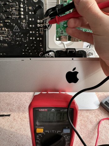
Provided you are thoroughly familiar with electrical safety rules – and only then – you may want to check the voltages across the two large electrolytic capacitors on the PSU board. The presence of approx. 390 V would suggest the problem is downstream of the intermediate circuit, the absence that current flow is cut somewhere upstream. I vaguely believe there is a fuse in the mains input circuitry but have no circuit diagram to verify.And while I see ~220 on the input and some components, there’s no 12V on the out. ... Wattmeter suggest the PSU still draws about 1 W but that’s pretty much it. I’m guessing whether I’m missing something or the PSU is faulty itself.
Thanks for your help.Correct. Check whether your PSU is indeed the same as mine (Delta Electronics ADP-300AF). Also, you may want to attach a small load such as a 12 V incandescent bulb, I am not sure how the PSU behaves with the output open.
Provided you are thoroughly familiar with electrical safety rules – and only then – you may want to check the voltages across the two large electrolytic capacitors on the PSU board. The presence of approx. 390 V would suggest the problem is downstream of the intermediate circuit, the absence that current flow is cut somewhere upstream. I vaguely believe there is a fuse in the mains input circuitry but have no circuit diagram to verify.
I suspect the PSU now.
The model is as written “ADP-AF300 AF T”.
I ran a test connecting a 12V fan (best I found at hand) and it showed no power being delivered.
I carefully checked components on the board, including the PET ones.
None, except for the marked one showed any voltage.
The marked ones showed ~238V as in my current power outlet at the moment.
Do you have any further ideas by chance?
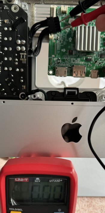
Could you please clarify what you mean by the acronym "PET" and where we are supposed to see marked components? And what do you know about the medical history of your iMac before you opened it? Did it show signs of life or remain completely dark and silent? By the way, I believe the fuse I mentioned before is a small brick-shaped component located next to the mains connector on the PCB. It cannot be accessed without removing the PSU from the iMac casing.I carefully checked components on the board, including the PET ones. None, except for the marked one showed any voltage.
The marked ones showed ~238V as in my current power outlet at the moment. Do you have any further ideas by chance?
Apologies, I was meant to attach the photo.Could you please clarify what you mean by the acronym "PET" and where we are supposed to see marked components? And what do you know about the medical history of your iMac before you opened it? Did it show signs of life or remain completely dark and silent? By the way, I believe the fuse I mentioned before is a small brick-shaped component located next to the mains connector on the PCB. It cannot be accessed without removing the PSU from the iMac casing.
By PET, I meant the PET capacitors (large batters) in the middle of the PCB. They’d occasionally show some voltage.
In red, where I saw some voltage.
The surrounding components didn’t have it.
I’ve got this PSU from China, so there’s much that I know about it. Rather than that I was promised it’s working.
Unfortunately, I couldn’t find any available in my country.
That you for the hint about the fuse.
Removing the PSU wouldn’t be a problem as I put it there in the first place
I’ll try to check if it’s alive.

I've got the same model PSU, Delta ADP-300AF T, from a 2013 27" iMac.
I have connected it to the 240v mains, and immediately (without touching any other connector)
I get 12v on the output plug, with no output load.
If yours doesn't do that it looks like it's broken :-(
The fuse is brown, next to the 120/240v input socket.
Edit: The top two pins (on the back of the PSU board) are negative and the bottom two pins are positive. On the 12 pin plug the top six pins are –ve and the bottom six +ve.
Last edited:
Thanks both!
Had to spend some time chatting with the seller, spend some time soldering.
Well, I can call myself now a certified PSU repairs shop
Had to resolder a few components (I did it badly, to be honest. I’m not good enough with the small components). But it worked after all, hey.
@PaulD-UK did I get you right it’s much, much better to connect the iMac button to the control board, not to the PSU?
Hi, good you could fix your PSU. 👍
I don’t think the iMac power switch does anything with the PSU. I think the original iMac logic board is needed to control the PSU.
So if you want to switch off the PSU in a DIY monitor you have to fit a new 120/240v switch in the power source.
The iMac switch will work fine for the new video board.
Last edited:
Hi, good you could fix you PSU. 👍
I don’t think the iMac power switch does anything with the PSU. I think the original iMac logic board is needed to control the PSU.
So if you want to switch off the PSU in a DIY monitor you have to fit a new 120/240v switch in the power source.
The iMac switch will work fine for the new video board.
Thank you
Confirmed with the tester, 12V are present doesn’t matter how many times I pressed the power button connected to the PSU.
UPD: example of my connection directly to the JRY board. Confirmed working.
I do not encourage soldering, using connectors would be a better way. But it’s good enough for me.

Last edited:
Question: has anyone been able to find 12V on the JRY board that can be controlled via the power button?
I’d like to connect the fan via Noctua controller.
However, I could not find any pins on the board that will meet the criteria.
I could use the in pins but obviously the wouldn’t be controlled via power button.
Or 5V on the IR pins that wouldn’t be enough for the Mac fan.
Thanks in advance.
I’d like to connect the fan via Noctua controller.
However, I could not find any pins on the board that will meet the criteria.
I could use the in pins but obviously the wouldn’t be controlled via power button.
Or 5V on the IR pins that wouldn’t be enough for the Mac fan.
Thanks in advance.
Hi, unlike the R1811, I don't think there is a source of simple 12v power from the JRY board.
Only the USB PD supply out of the USB-C port - which isn't a good idea to fiddle with without proper expertise.
There may be 12v on the DC_In/Gnd pins on the 10 pin alternative power-in socket at the top of the board, next to the eDP connecter.
But if there is this may not be switched? You would need to test that to find out if you could use that...
A better source of 5v is from the USB socket next to the HDMI port - the power pins are clearly marked.
This also would need to be investigated if it is switched off in standby mode.
The iMac's original fan will work if you feed 5v to its 2 power wires. It will stop rotating at less than about 4.5v, but will run well at 5v. However it will be quite noisy run this way.
A better (quieter) solution is to use a 4 wire PWM controller, like this post from the iMac forum.
Here a step-up voltage converter is also used.
Converter: https://crjelectronics.com/products/4041
PWM controller: https://noctua.at/en/na-fc1
A cheaper step-up voltage converter and PWM controller from AliExpress etc would be suitable.
Whether the JRY's USB socket can supply enough power would have to be tested...
But you wouldn't need to run the fan at more than 25-30% full speed. probably less, and a properly spec'd USB A port should supply 5V 500mA which should be enough to run the fan at the speed you would need.
If you run the iMac fan at more than ~2.5w you would risk overloading the JRY USB socket, so test carefully...
I found I didn't need to use a 27" iMac fan, as it is much too powerful.
So I fitted the fan from an A1418 21" iMac, which is totally inaudible at the ~25% speed I run it at. Link.
I should not use the IR power, as its power rating will be less.
Last edited:
Paul, could you check if the USB pins on your board show any signs of voltage?Hi, unlike the R1811, I don't think there is a source of simple 12v power from the JRY board.
Only the USB PD supply out of the USB-C port - which isn't a good idea to fiddle with without proper expertise.
There may be 12v on the DC_In/Gnd pins on the 10 pin alternative power-in socket at the top of the board, next to the eDP connecter.
But if there is this may not be switched? You would need to test that to find out if you could use that...
A better source of 5v is from the USB socket next to the HDMI port - the power pins are clearly marked.
This also would need to be investigated if it is switched off in standby mode.
The iMac's original fan will work if you feed 5v to its 2 power wires. It will stop rotating at less than about 4.5v, but will run well at 5v. However it will be quite noisy run this way.
A better (quieter) solution is to use a 4 wire PWM controller, like this post from the iMac forum.
Here a step-up voltage converter is also used.
Converter: https://crjelectronics.com/products/4041
PWM controller: https://noctua.at/en/na-fc1
A cheaper step-up voltage converter and PWM controller from AliExpress etc would be suitable.
Whether the JRY's USB socket can supply enough power would have to be tested...
But you wouldn't need to run the fan at more than 25-30% full speed. probably less, and a properly spec'd USB A port should supply 5V 500mA which should be enough to run the fan at the speed you would need.
If you run the iMac fan at more than ~2.5w you would risk overloading the JRY USB socket, so test carefully...
I found I didn't need to use a 27" iMac fan, as it is much too powerful.
So I fitted the fan from an A1418 21" iMac, which is totally inaudible at the ~25% speed I run it at. Link.
I should not use the IR power, as its power rating will be less.
The 4 unused pins on mine don’t show any signs. The pins of the functional usb-A ports do, however.
Also, advice to everyone else: IR pins provide voltage even if the board is turned off. Which is quite logic but I didn’t think about it advance.
I can also confirm that the iMac 27 fan with the Noctua controller works nicely from the 5V.
I tend to solder the pins to the one of one of the usb ports. I think it should be fine, as it draws very little of power.
—-
I’d also mention that the camera installation per Aiwi’s guide failed for me. I didn’t realise that my screen (2020 model) has the mounting point directly on it. While I ordered a bracket as Aiwi used.
I’ll try to cut the mounts on the display next weekend. As they don’t seem to be detachable and the camera currently doesn’t fit, being too thick for the display to close.
—-
Personal impression about the MEMS mic per Aiwi’s guide: too sensitive.
I’ve got one failed mic and I decided to use only one. Maybe that is the reason.
But the Mic picks up too easily any background noise, even being outside of the case.
Which makes it fairly unusable, as the other party on Zoom hears too many undesired sounds.
However, a generic USB mic turned out even worse. It’s not sensitive enough while in the case. So you can’t be heard.
For now, I’d drop this idea of having a built-in mic.
Presumably there is no charging over USB-C if you attach a laptop as Power Delivery requires 20v?Power supply
Why use a separate power brick when there is a power supply in working condition? In the A1419 model, the built-in unit (Delta Electronics ADP-300AF) delivers a single regulated 12.1 V voltage and all other supply voltages get derived from there on the mainboard. The current rating of 25 A is amply sufficient for the 5 to 7 A drawn by the R9A18. Testing with 12 V light bulbs from car headlights revealed the power supply is always on as long as the iMac stays connected to the mains. A word of caution: Beware of the 230 V AC in the mains circuit and of the 390 V DC that build up across some capacitors! While I observed that the DC voltages dissipate within a minute or so after separating the power supply from the mains, I insist you check yourself before touching anything.
Right. Power Delivery was not a priority for me as I plan to charge via MagSafe which does not occupy any USB-C port.Presumably there is no charging over USB-C if you attach a laptop as Power Delivery requires 20v?
Although your question refers to a poster who has used the internal iMac 12V 300W supply with an RA918, I can confirm that the JRY board advertises itself as a 27W charger (I assume 9.0V@3A) when powered by an external 12V supply (in my case a 72W 12V@6A supply) and connected via a single USB-C cable to a Macbook Pro M1.Presumably there is no charging over USB-C if you attach a laptop as Power Delivery requires 20v?
Register on MacRumors! This sidebar will go away, and you'll see fewer ads.