Become a MacRumors Supporter for $50/year with no ads, ability to filter front page stories, and private forums.

rockyhill

macrumors regular
Dec 24, 2016
214
67
Miami Fl, United States
@anotherelise

I changed the loading the arrays of property values to just loading arrays with start and end values for each property.
Unfortunately the arrays were taking up too much memory and I was occasionally seeing erratic behavior with my
setup. I also changed the max and min values for most of them by either +1 or -1 so that picture wouldn't reset.

I pushed the changes a little while ago, try it out when you have some time.

Hopefully this weekend I can get two more init captures
 
  • Like
Reactions: anotherelise

oshimai

macrumors member
Apr 7, 2020
53
31
Europe
@oshimai

Hmm one second is a bit too long especially if the fine monitor adjustments depend on the loop but
pulsein has a third parameter which is a timeout value given in microseconds. The loop currently
has a delay of 10 millseconds so maybe the timeout for pulsein can be 10000 microseconds.
This will give it the dual purpose of detecting VSYNC pulses and serve as the loops timeout.

If there are no changes for say 5 seconds the monitor shuts off.

Yeah I know about that parameter. 10000 Microseconds won't work since the pulses are a little over that. Also when they occur is dependent on the refresh rate. This is tricky to get right universally.

Maybe the version with interrupts is better after all?

Code:
#include <Wire.h>

#define LED 22

// You can't just use ANY pin!
// See https://www.arduino.cc/reference/en/language/functions/external-interrupts/attachinterrupt/
// Section "Interrupt Numbers"
#define VSYNC 2
volatile unsigned long LAST_VSYNC = 0;

// boilerplate stuff
void requestEvent() {
  const byte edid[128] = {
    0x00, 0xff, 0xff, 0xff, 0xff, 0xff, 0xff, 0x00, 0x06, 0x10, 0x05, 0x9d,
    0x01, 0x01, 0x01, 0x01, 0x00, 0x08, 0x01, 0x01, 0x08, 0x1b, 0x14, 0x96,
    0xe8, 0x66, 0xe9, 0x9c, 0x57, 0x4c, 0x96, 0x26, 0x10, 0x48, 0x4c, 0x00,
    0x02, 0x00, 0x01, 0x01, 0x01, 0x01, 0x01, 0x01, 0x01, 0x01, 0x01, 0x01,
    0x01, 0x01, 0x01, 0x01, 0x01, 0x01, 0x88, 0x13, 0x80, 0xc0, 0x20, 0xe0,
    0x22, 0x10, 0x10, 0x40, 0x13, 0x00, 0x0e, 0xc8, 0x10, 0x00, 0x00, 0x1e,
    0x60, 0x18, 0x20, 0xf0, 0x30, 0x58, 0x20, 0x20, 0x10, 0x50, 0x13, 0x00,
    0x0e, 0xc8, 0x10, 0x00, 0x00, 0x1e, 0x00, 0x00, 0x00, 0xfd, 0x00, 0x4b,
    0x75, 0x3c, 0x3c, 0x08, 0x00, 0x0a, 0x20, 0x20, 0x20, 0x20, 0x20, 0x20,
    0x00, 0x00, 0x00, 0xfc, 0x00, 0x69, 0x4d, 0x61, 0x63, 0x0a, 0x20, 0x20,
    0x20, 0x20, 0x20, 0x20, 0x20, 0x20, 0x00, 0xc9
  };

  Wire.write(edid, 128);
}

void receiveData(int byteCount) {
  while (Wire.available())
    Wire.read();
}
// end boilerplate

void setup() {
  Wire.begin(0x50);
  Wire.onRequest(requestEvent);
  Wire.onReceive(receiveData);

  pinMode(LED, OUTPUT);

  pinMode(VSYNC, INPUT);
  attachInterrupt(digitalPinToInterrupt(VSYNC), vsync_interrupt_proc, CHANGE);
}

void loop() {
  noInterrupts();
  unsigned long tmp = LAST_VSYNC;
  interrupts();

  if (tmp != 0 && millis() - tmp < 5000)
    digitalWrite(LED, HIGH);
  else
    digitalWrite(LED, LOW);
}

void vsync_interrupt_proc()
{
  LAST_VSYNC = millis();
}

that aside.

I just finished building the CD drive. There's some China company selling refurbished slot in multi drives that are "Mac Mini compatible" on Amazon. https://www.amazon.co.uk/dp/B075CGTGT7

The only reason I mention them is that if the drive is crap, you can just send it back to Amazon. If you go the eBay route to get a suitable drive, you're out of luck if it's garbage. What kind of drive you get seems to be random. I got a "HL-DT-ST DVDRAM GA10F USB Device". There's just enough space for the drive along with a mSATA to USB adapter to fit comfortably. Also, that plastic mold that @Spanky Deluxe mentioned is awesome. It helps keep the drive in place inside the original Apple cage without drilling new screw holes.

And another thing for the software TODO list, a service that ejects CDs when you shut down the computer. Pain in the ass on Windows, but on Linux I assume this would just be an init script that calls the "eject" command on stop.


May I ask what people are using as an amplifier for the speakers? Is an PAM8403 enough? It has dedicated mute and shutdown pins which would work really nicely together with the headphone sense. The Arduino should be able to handle the required glue logic easily.
 

rockyhill

macrumors regular
Dec 24, 2016
214
67
Miami Fl, United States
Yeah I know about that parameter. 10000 Microseconds won't work since the pulses are a little over that. Also when they occur is dependent on the refresh rate. This is tricky to get right universally.

Maybe the version with interrupts is better after all?

Code:
#include <Wire.h>

#define LED 22

// You can't just use ANY pin!
// See https://www.arduino.cc/reference/en/language/functions/external-interrupts/attachinterrupt/
// Section "Interrupt Numbers"
#define VSYNC 2
volatile unsigned long LAST_VSYNC = 0;

// boilerplate stuff
void requestEvent() {
  const byte edid[128] = {
    0x00, 0xff, 0xff, 0xff, 0xff, 0xff, 0xff, 0x00, 0x06, 0x10, 0x05, 0x9d,
    0x01, 0x01, 0x01, 0x01, 0x00, 0x08, 0x01, 0x01, 0x08, 0x1b, 0x14, 0x96,
    0xe8, 0x66, 0xe9, 0x9c, 0x57, 0x4c, 0x96, 0x26, 0x10, 0x48, 0x4c, 0x00,
    0x02, 0x00, 0x01, 0x01, 0x01, 0x01, 0x01, 0x01, 0x01, 0x01, 0x01, 0x01,
    0x01, 0x01, 0x01, 0x01, 0x01, 0x01, 0x88, 0x13, 0x80, 0xc0, 0x20, 0xe0,
    0x22, 0x10, 0x10, 0x40, 0x13, 0x00, 0x0e, 0xc8, 0x10, 0x00, 0x00, 0x1e,
    0x60, 0x18, 0x20, 0xf0, 0x30, 0x58, 0x20, 0x20, 0x10, 0x50, 0x13, 0x00,
    0x0e, 0xc8, 0x10, 0x00, 0x00, 0x1e, 0x00, 0x00, 0x00, 0xfd, 0x00, 0x4b,
    0x75, 0x3c, 0x3c, 0x08, 0x00, 0x0a, 0x20, 0x20, 0x20, 0x20, 0x20, 0x20,
    0x00, 0x00, 0x00, 0xfc, 0x00, 0x69, 0x4d, 0x61, 0x63, 0x0a, 0x20, 0x20,
    0x20, 0x20, 0x20, 0x20, 0x20, 0x20, 0x00, 0xc9
  };

  Wire.write(edid, 128);
}

void receiveData(int byteCount) {
  while (Wire.available())
    Wire.read();
}
// end boilerplate

void setup() {
  Wire.begin(0x50);
  Wire.onRequest(requestEvent);
  Wire.onReceive(receiveData);

  pinMode(LED, OUTPUT);

  pinMode(VSYNC, INPUT);
  attachInterrupt(digitalPinToInterrupt(VSYNC), vsync_interrupt_proc, CHANGE);
}

void loop() {
  noInterrupts();
  unsigned long tmp = LAST_VSYNC;
  interrupts();

  if (tmp != 0 && millis() - tmp < 5000)
    digitalWrite(LED, HIGH);
  else
    digitalWrite(LED, LOW);
}

void vsync_interrupt_proc()
{
  LAST_VSYNC = millis();
}

that aside.

I just finished building the CD drive. There's some China company selling refurbished slot in multi drives that are "Mac Mini compatible" on Amazon. https://www.amazon.co.uk/dp/B075CGTGT7

The only reason I mention them is that if the drive is crap, you can just send it back to Amazon. If you go the eBay route to get a suitable drive, you're out of luck if it's garbage. What kind of drive you get seems to be random. I got a "HL-DT-ST DVDRAM GA10F USB Device". There's just enough space for the drive along with a mSATA to USB adapter to fit comfortably. Also, that plastic mold that @Spanky Deluxe mentioned is awesome. It helps keep the drive in place inside the original Apple cage without drilling new screw holes.

And another thing for the software TODO list, a service that ejects CDs when you shut down the computer. Pain in the ass on Windows, but on Linux I assume this would just be an init script that calls the "eject" command on stop.


May I ask what people are using as an amplifier for the speakers? Is an PAM8403 enough? It has dedicated mute and shutdown pins which would work really nicely together with the headphone sense. The Arduino should be able to handle the required glue logic easily.

@oshimai


When I get a chance I'll test out the interrupt method and hopefully we could get something going because this idea of yours is
a very good option to glue the machine to the CRT . Consequently the arduino could also eject a disk via the VSYNC method if it can't be done with the computer.

I bought a slimline usb to slimline sata adapter with an eject button for interfacing to the arduino.
https://www.amazon.com/gp/product/B00NASXRHM/ref=ppx_yo_dt_b_asin_title_o03_s00?ie=UTF8&psc=1

I believe System V had what are called kill scripts that you place inside /etc/init.d and as long as it was executable and the filename started with a "k" it would run when shutting down. I'm not sure how to do that with systemd other with than a daemon but I'll search around.

I've already received the moldable plastic recommended by spanky but I haven't used it, I'm not quite there yet.


I ordered a batch of 5 PAM8403 chips and tested them. They are dirt cheap and they pack a lot more power than
I expected. I have a video testing the amp but there is interference from the computer because I tested it before I
received the ground loop isolator .

Which PAM8403 board did you see? The one I have doesn't come with mute and shutdown breakout.


rockyhill

macrumors regular
Dec 24, 2016
214
67
Miami Fl, United States
@oshimai

I got the VSYNC detect to work! It might need some more massaging but it seems good.
I'll see if I can update the PCB design soonish. Thanks for the recommendation, great addition!

check out the video.


Here is a picture of the jumper
VSYNC_jumper.jpg
 
Last edited:
  • Like
Reactions: oshimai

oshimai

macrumors member
Apr 7, 2020
53
31
Europe
@oshimai

I got the VSYNC detect to work! It might need some more massaging but it seems good.
I'll see if I can update the PCB design soonish. Thanks for the recommendation, great addition!

Awesome. Now I can put "Extensive Embedded Controller Development Experience" on my CV (that was my first Arduino project).

Dumb joke aside, I'm glad I was able to give back something.

@oshimaiI ordered a batch of 5 PAM8403 chips and tested them. They are dirt cheap and they pack a lot more power than I expected. I have a video testing the amp but there is interference from the computer because I tested it before I received the ground loop isolator .

Which PAM8403 board did you see? The one I have doesn't come with mute and shutdown breakout.

Whatever the cheapest one on Amazon was. Foxnovo High Power Audio Amplifier or something like that. I'll get it some time next week. It's a red board and you should be able to find it pretty much anywhere.

Looks like this. I think SW is mute.

d.jpg
 

oshimai

macrumors member
Apr 7, 2020
53
31
Europe
Headphone sense is working. Use analogRead(). Any value over 100 means headphone plugged in.

For people in the future who are attempting this, USE ROCKYHILL'S PCBS

I do all of this with jumper wires and it is a giant pain in the ass.
foto_no_exif.jpg

Yes that's a GB Pocket running Tetris as a sound generator.
 

rockyhill

macrumors regular
Dec 24, 2016
214
67
Miami Fl, United States
Awesome. Now I can put "Extensive Embedded Controller Development Experience" on my CV (that was my first Arduino project).

Dumb joke aside, I'm glad I was able to give back something.


Whatever the cheapest one on Amazon was. Foxnovo High Power Audio Amplifier or something like that. I'll get it some time next week. It's a red board and you should be able to find it pretty much anywhere.

Looks like this. I think SW is mute.

View attachment 906435

You should definitely put that on your resume.
 

rockyhill

macrumors regular
Dec 24, 2016
214
67
Miami Fl, United States
Awesome. Now I can put "Extensive Embedded Controller Development Experience" on my CV (that was my first Arduino project).

Dumb joke aside, I'm glad I was able to give back something.


Whatever the cheapest one on Amazon was. Foxnovo High Power Audio Amplifier or something like that. I'll get it some time next week. It's a red board and you should be able to find it pretty much anywhere.

Looks like this. I think SW is mute.

View attachment 906435

I updated the PCB with a VSYNC detect line and uploaded it to the repo.
 

oshimai

macrumors member
Apr 7, 2020
53
31
Europe
The amplifier board arrived super quickly, but the sound is quiet and garbled.
Getting 0.029V DC on the outputs. Something is very screwed up.

I'm worried about damaging the speakers.
 

oshimai

macrumors member
Apr 7, 2020
53
31
Europe
Do you think you have a defective board? Can you test it with another pair of speakers?

Looks like a defective board.

To avoid damaging the iMac speakers I cut a USB cable in half and tried to feed the PAM8403 5V via that, so I could do all testing away from the Mac. After a few seconds, the chip got so hot that I burnt my finger when touching it. That's with only power connected. Something must have shorted out inside the chip. Now I have a tiny space heater. :(

F*ck it. I'm a software engineer, not an electronic engineer. I'll try this next, it looks a lot more idiot-proof.
 
  • Like
Reactions: rockyhill

rockyhill

macrumors regular
Dec 24, 2016
214
67
Miami Fl, United States
Looks like a defective board.

To avoid damaging the iMac speakers I cut a USB cable in half and tried to feed the PAM8403 5V via that, so I could do all testing away from the Mac. After a few seconds, the chip got so hot that I burnt my finger when touching it. That's with only power connected. Something must have shorted out inside the chip. Now I have a tiny space heater. :(

F*ck it. I'm a software engineer, not an electronic engineer. I'll try this next, it looks a lot more idiot-proof.

Sometimes you get what you pay for and with these boards I've read it isn't uncommon. But hey, it was dirt cheap.
Those boards definitely look like a safer bet.

It has dual inputs?
[automerge]1587178137[/automerge]
@rockyhill Would you do an i2c capture of your iMac booting up? I want to start getting into what the values that we read back from the ivad are and it'd help to have more than just my capture.

@anotherelise

As promised, I've included another raw capture of an initialization along with a capture of when the logic board blanks the screen
and a capture of when it wakes it.

They are all in the raw_data folder
The three files are .
"imac_ivad_init_2_rocky_hill.csv"
"imac_g3_ivad_blanking_capture.csv"
"imac_g3_ivad_waking_capture.csv"

I carefully removed the bottom of my "new" iMac and soldered wires onto the logic board to monitor the i2c lines. I didn't have to remove any other part of the case "whew!" . I reassembled it and now I have wires sticking out of it for future captures.

Here's are some pics.

20200417_174036.jpg
20200417_172037.jpg
20200417_202333.jpg
 
Last edited:

oshimai

macrumors member
Apr 7, 2020
53
31
Europe
I went with this for the amplifier instead. https://www.adafruit.com/product/987
To be powered by the J22 AC pins with a small rectifier/voltage converter.
Fingers crossed that it works better. It will arrive soon.


I hate to bring the dreaded EDID discussion back up again since I thought that was complete once I got the Apple EDID out of the logic board via the /sys colder.

First an observation about edid-decode: the version shipping with Debian/Devuan is old and has bugs that flag valid EDIDs as invalid. I grabbed a more recent version from https://github.com/timvideos/edid-decode/. The official repository seems to be https://git.linuxtv.org/edid-decode.git/ but there it somehow turned from a single C file into some object oriented multi-file C++ monster so just I left it alone.

The timvideos copy compiles with standard gcc.

It parses the Apple EDID as

Code:
root@devuan:~# ./edid-decode EDID
EDID version: 1.1
Manufacturer: APP Model 9d05 Serial Number 16843009
Analog display, Input voltage level: 0.7/0.3 V
Sync: Separate
Maximum image size: 27 cm x 20 cm
Gamma: 2.50
DPMS levels: Standby Suspend Off
RGB color display
Display x,y Chromaticity:
  Red:   0.6103, 0.3417
  Green: 0.2978, 0.5878
  Blue:  0.1513, 0.0644
  White: 0.2832, 0.2978
Established timings supported:
  1024x768@75Hz 4:3 HorFreq: 60000 Hz Clock: 78.750 MHz
Standard timings supported:
Detailed mode: Clock 50.000 MHz, 270 mm x 200 mm
                640  656  720  832 hborder 0
                480  481  484  514 vborder 0
               +hsync +vsync
               VertFreq: 116 Hz, HorFreq: 60096 Hz
Detailed mode: Clock 62.400 MHz, 270 mm x 200 mm
                800  816  896 1040 hborder 0
                600  601  604  632 vborder 0
               +hsync +vsync
               VertFreq: 94 Hz, HorFreq: 60000 Hz
Monitor ranges (GTF): 75-117Hz V, 60-60kHz H, max dotclock 80MHz
Monitor name: iMac
Checksum: 0xc9 (valid)

So all those reported non-conformance errors were none.

One thing that sucks is that it states "Standard timings supported" as none. Instead you get one established timing and two detailed modes. Great, but left as-is, a Windows PC will refuse to show a picture on the screen at any resolution other than 1024x768@75. Sucks for old games.

I found a program called "AW EDID Editor" (Windows only) and recreated the Apple EDID as an EDID 1.4 compliant version that adds 640x480 and 800x600 to the list of standard timings. That causes them to show up in the display control panel.

Note: try to open the Apple EDID with it and it crashes immediately. Only by slowly hex editing the Apple EDID bits into a blank template created by that program, I'm now at:

Code:
root@devuan:~# ./edid-decode a.bin
EDID version: 1.4
Manufacturer: APP Model 9d05 Serial Number 16843009
Analog display, Input voltage level: 0.7/0.3 V
Blank level equals black level
Sync: Separate
Maximum image size: 27 cm x 20 cm
Gamma: 2.50
DPMS levels: Standby Suspend Off
RGB color display
Display x,y Chromaticity:
  Red:   0.6103, 0.3417
  Green: 0.2978, 0.5878
  Blue:  0.1513, 0.0644
  White: 0.2832, 0.2978
Established timings supported:
  1024x768@75Hz 4:3 HorFreq: 60000 Hz Clock: 78.750 MHz
Standard timings supported:
  640x480@117Hz 4:3
  800x600@95Hz 4:3
Detailed mode: Clock 50.000 MHz, 270 mm x 200 mm
                640  656  720  832 hborder 0
                480  481  484  514 vborder 0
               +hsync +vsync
               VertFreq: 116 Hz, HorFreq: 60096 Hz
Detailed mode: Clock 62.400 MHz, 270 mm x 200 mm
                800  816  896 1040 hborder 0
                600  601  604  632 vborder 0
               +hsync +vsync
               VertFreq: 94 Hz, HorFreq: 60000 Hz
Monitor ranges (GTF): 75-117Hz V, 60-60kHz H, max dotclock 80MHz
Monitor name: iMac G3
Checksum: 0x3d (valid)
root@devuan:~#


Note the changed version and additional standard timings listed.
I changed the monitor name so it doesn't clash with the original EDID.

There's still a problem though. During the Windows boot process, you currently get a blank screen. It appears Windows reeeeeeeeeeally wants to use 1024x768@60 and if it's not supported, the screen just turns off completely (no VSYNC). I don't buy into the whole "dOn't InSTaLl wInDoWS on AN appLE COmpuTeR. thaT's Not whAT it WAS bUilT FOR" thing, so hopefully that problem can be fixed with some more EDID tinkering. I'll post an update later.
 

rockyhill

macrumors regular
Dec 24, 2016
214
67
Miami Fl, United States
I went with this for the amplifier instead. https://www.adafruit.com/product/987
To be powered by the J22 AC pins with a small rectifier/voltage converter.
Fingers crossed that it works better. It will arrive soon.


I hate to bring the dreaded EDID discussion back up again since I thought that was complete once I got the Apple EDID out of the logic board via the /sys colder.

First an observation about edid-decode: the version shipping with Debian/Devuan is old and has bugs that flag valid EDIDs as invalid. I grabbed a more recent version from https://github.com/timvideos/edid-decode/. The official repository seems to be https://git.linuxtv.org/edid-decode.git/ but there it somehow turned from a single C file into some object oriented multi-file C++ monster so just I left it alone.

The timvideos copy compiles with standard gcc.

It parses the Apple EDID as

Code:
root@devuan:~# ./edid-decode EDID
EDID version: 1.1
Manufacturer: APP Model 9d05 Serial Number 16843009
Analog display, Input voltage level: 0.7/0.3 V
Sync: Separate
Maximum image size: 27 cm x 20 cm
Gamma: 2.50
DPMS levels: Standby Suspend Off
RGB color display
Display x,y Chromaticity:
  Red:   0.6103, 0.3417
  Green: 0.2978, 0.5878
  Blue:  0.1513, 0.0644
  White: 0.2832, 0.2978
Established timings supported:
  1024x768@75Hz 4:3 HorFreq: 60000 Hz Clock: 78.750 MHz
Standard timings supported:
Detailed mode: Clock 50.000 MHz, 270 mm x 200 mm
                640  656  720  832 hborder 0
                480  481  484  514 vborder 0
               +hsync +vsync
               VertFreq: 116 Hz, HorFreq: 60096 Hz
Detailed mode: Clock 62.400 MHz, 270 mm x 200 mm
                800  816  896 1040 hborder 0
                600  601  604  632 vborder 0
               +hsync +vsync
               VertFreq: 94 Hz, HorFreq: 60000 Hz
Monitor ranges (GTF): 75-117Hz V, 60-60kHz H, max dotclock 80MHz
Monitor name: iMac
Checksum: 0xc9 (valid)

So all those reported non-conformance errors were none.

One thing that sucks is that it states "Standard timings supported" as none. Instead you get one established timing and two detailed modes. Great, but left as-is, a Windows PC will refuse to show a picture on the screen at any resolution other than 1024x768@75. Sucks for old games.

I found a program called "AW EDID Editor" (Windows only) and recreated the Apple EDID as an EDID 1.4 compliant version that adds 640x480 and 800x600 to the list of standard timings. That causes them to show up in the display control panel.

Note: try to open the Apple EDID with it and it crashes immediately. Only by slowly hex editing the Apple EDID bits into a blank template created by that program, I'm now at:

Code:
root@devuan:~# ./edid-decode a.bin
EDID version: 1.4
Manufacturer: APP Model 9d05 Serial Number 16843009
Analog display, Input voltage level: 0.7/0.3 V
Blank level equals black level
Sync: Separate
Maximum image size: 27 cm x 20 cm
Gamma: 2.50
DPMS levels: Standby Suspend Off
RGB color display
Display x,y Chromaticity:
  Red:   0.6103, 0.3417
  Green: 0.2978, 0.5878
  Blue:  0.1513, 0.0644
  White: 0.2832, 0.2978
Established timings supported:
  1024x768@75Hz 4:3 HorFreq: 60000 Hz Clock: 78.750 MHz
Standard timings supported:
  640x480@117Hz 4:3
  800x600@95Hz 4:3
Detailed mode: Clock 50.000 MHz, 270 mm x 200 mm
                640  656  720  832 hborder 0
                480  481  484  514 vborder 0
               +hsync +vsync
               VertFreq: 116 Hz, HorFreq: 60096 Hz
Detailed mode: Clock 62.400 MHz, 270 mm x 200 mm
                800  816  896 1040 hborder 0
                600  601  604  632 vborder 0
               +hsync +vsync
               VertFreq: 94 Hz, HorFreq: 60000 Hz
Monitor ranges (GTF): 75-117Hz V, 60-60kHz H, max dotclock 80MHz
Monitor name: iMac G3
Checksum: 0x3d (valid)
root@devuan:~#


Note the changed version and additional standard timings listed.
I changed the monitor name so it doesn't clash with the original EDID.


There's still a problem though. During the Windows boot process, you currently get a blank screen. It appears Windows reeeeeeeeeeally wants to use 1024x768@60 and if it's not supported, the screen just turns off completely (no VSYNC). I don't buy into the whole "dOn't InSTaLl wInDoWS on AN appLE COmpuTeR. thaT's Not whAT it WAS bUilT FOR" thing, so hopefully that problem can be fixed with some more EDID tinkering. I'll post an update later.


Are you already displaying stuff on your CRT? If so, please show it in action! I'm really curios to see the mod working
on the other side of the pond.

Are you transmitting the EDID with an arduino? If you are, then the BIOS should just pick it up and you'll see
the computer POST. I've tried it on several computers with a VGA out.

Does the pc you're using have a VGA connector or are you using an HDMI to VGA converter?
An HDMI to VGA converter can cause EDID transmission issues.

I actually used the same EDID program to create the first EDID! It works well under wine. I tested the original EDID I created with Windows 10 and it works well, supporting 1024x768 @ 75hz and 800x600 @95hz.

I haven't tried the default one(the one you provided) with windows 10 but I'm sure it'll work because it works with my linux computer.

I think 1024x768 @ 75hz is the only standard resolution and refresh rate this is capable of however.


That amp you bought looks promising but I recommend you purchase a ground loop isolator. I had soooooooooo much
interference with every single amp I tried. the isolator eliminates it all.
 

rockyhill

macrumors regular
Dec 24, 2016
214
67
Miami Fl, United States
There's still a problem though. During the Windows boot process, you currently get a blank screen. It appears Windows reeeeeeeeeeally wants to use 1024x768@60 and if it's not supported, the screen just turns off completely (no VSYNC). I don't buy into the whole "dOn't InSTaLl wInDoWS on AN appLE COmpuTeR. thaT's Not whAT it WAS bUilT FOR" thing, so hopefully that problem can be fixed with some more EDID tinkering. I'll post an update later.


I just popped into the attic and pulled out my Win10 box and tried it with the EDID you provided and it was flawless.
I was able to use all three supported resolutions. I can post a video if you want to see what it looks like.
let me know.
 

oshimai

macrumors member
Apr 7, 2020
53
31
Europe
I didn't really want to show off my jumper wire mess, but if you insist. :/


Everything works except the audio portion at the moment.

The BIOS POSTs so quickly you don't see anything, but that part always worked, even without an EDID. Then Windows boots which the CRT currently can't handle until I find a workaround and once Windows is up the CRT turns back on with the proper resultion and shows the desktop.

I luckily have a dedicated VGA connector. The HDMI port is only being used to clone the display so I don't have to use Windows upside down until I finish up the project. I don't want to turn the iMac around until I've finished the audio bits, done some cable management and secured all the jumper wires in place.


Let me retest the original Apple EDID with Win7. Maybe I messed up something before and came to wrong conclusions.
 
  • Like
Reactions: rockyhill

oshimai

macrumors member
Apr 7, 2020
53
31
Europe
What SBC are you using, I haven't settled on one yet but yours looks fantastic.

BTW here are the supported resolutions the EDID offers to windows 10 and they all work!

The PC is a Gigabyte BRIX GB-BACE-3160 but I think they don't sell it anymore. I had it sitting around unused and didn't want to sink too much money into this project. I soldered wires onto the power button and drive that with one of the relays on the relay board.

To do this properly you could use any PC/104 board though.

Example: https://advdownload.advantech.com/p...sheet/PCM-3365_DS(02.06.17)20170213144206.pdf

They are perfect since they have no connectors directly on the board, just pins that you hook up the supplied cables to. You just connect what you need. For example this project doesn't really need a DE-15 VGA connector, you can just wire up the pins directly. It also means you can populate the side panel on the iMac with USB, LAN, etc. without having to get super creative. They're usually also passively cooled.

You could even keep the Apple down converter board and use it as the power source. :p

That Windows 10 display mode list made me go "WTF?!".
With the Apple EDID I get this on Win7:
1024 X 768 75 Hz

With my edits to bring it up to EDID 1.4 I can get to this:
640 X 480 117 Hz
800 X 600 95 Hz
1024 X 768 75 Hz

I used this tool to compare: https://www.nirsoft.net/utils/monitor_info_view.html

This is on Intel Graphics from the above GB-BACE-3160. I think what resolutions show up may be dependent on the video controller in the PC that's driving the CRT, and maybe also the version of Windows. I'll try with Win10 later.
 

rockyhill

macrumors regular
Dec 24, 2016
214
67
Miami Fl, United States
The PC is a Gigabyte BRIX GB-BACE-3160 but I think they don't sell it anymore. I had it sitting around unused and didn't want to sink too much money into this project. I soldered wires onto the power button and drive that with one of the relays on the relay board.

To do this properly you could use any PC/104 board though.

Example: https://advdownload.advantech.com/productfile/PIS/PCM-3365/Product - Datasheet/PCM-3365_DS(02.06.17)20170213144206.pdf

They are perfect since they have no connectors directly on the board, just pins that you hook up the supplied cables to. You just connect what you need. For example this project doesn't really need a DE-15 VGA connector, you can just wire up the pins directly. It also means you can populate the side panel on the iMac with USB, LAN, etc. without having to get super creative. They're usually also passively cooled.

You could even keep the Apple down converter board and use it as the power source. :p

That Windows 10 display mode list made me go "WTF?!".
With the Apple EDID I get this on Win7:
1024 X 768 75 Hz

With my edits to bring it up to EDID 1.4 I can get to this:
640 X 480 117 Hz
800 X 600 95 Hz
1024 X 768 75 Hz

I used this tool to compare: https://www.nirsoft.net/utils/monitor_info_view.html

This is on Intel Graphics from the above GB-BACE-3160. I think what resolutions show up may be dependent on the video controller in the PC that's driving the CRT, and maybe also the version of Windows. I'll try with Win10 later.

Looks l'm going to have to get a pc104 board off of ebay or something, completely forgot about that form factor, it's perfect for this!
That tool looks really good to have around too. So do you think you can make an EDID with extended data in it? Maybe one that
can be passed through an HDMI to VGA adapter for easy configuration?

I think you're right, the offered resolutions depend on the video card.....
 

oshimai

macrumors member
Apr 7, 2020
53
31
Europe
I'll put up an updated EDID when I post all of the code I've been working on.

Wait, I just realized you were testing with a rectifier/voltage converter. Can't wait to
hear about the results!

Not having much luck on the hardware side. :(
- First AC/DC converter board was DOA, but the second one worked
- The Adafruit amp had huge amounts of static, turns out my soldering was garbage; redoing it fixed it
- Then the speakers decided now would be the perfect time to disintegrate (foam rot)

I picked at the foam a bit using a screwdriver to see if the amp blew the speakers or if they just decided to die and it seems to be the latter. The foam I picked at just turned into lots of little flakes. When I push the speaker coils back a bit and hold them in their intended position by hand, I get clear, loud sound (using the GameBoy as a sound generator atm) without noise. When I let go, it just goes really quiet and sounds weird, and either the left or right speaker coil comes out really far.

I don't know a lot about the specifics of how speakers work exactly, but I guess that foam was once supposed to hold the coils (the part that moves back and forth and makes sound waves) in position so they don't come out too far. I hope that's correct?

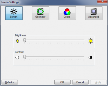
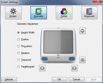
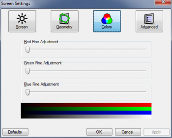
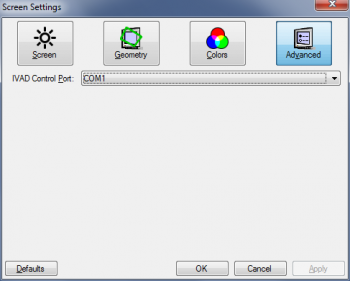
On the software side, I realized that the Arduino EEPROM is only good for 100k or so write cycles so I'm trying to get a wear leveling library working before I wire up the GUI to load from/write to it. My Windows GUI is done.
 

Attachments

  • Capture.PNG
    Capture.PNG
    24.3 KB · Views: 85
  • Capture1.PNG
    Capture1.PNG
    55.5 KB · Views: 120
  • Capture2.PNG
    Capture2.PNG
    28.1 KB · Views: 104
  • Capture3.PNG
    Capture3.PNG
    23.3 KB · Views: 82

rockyhill

macrumors regular
Dec 24, 2016
214
67
Miami Fl, United States
Then the speakers decided now would be the perfect time to disintegrate (foam rot)

Yeah, the foam does keep the coils from popping out and they move the air to produce the sound.
At this age, I think it's pretty safe to assume that they all suffer from foam rot. I had to replace mine, luckily I found
replacement speakers that were a perfect fit. Not too expensive either. I'm sure you've seen the videos
but here is one I made with a link to the speakers I bought under it.

Ebay speakers


On the software side, I realized that the Arduino EEPROM is only good for 100k or so write cycles so I'm trying to get a wear leveling library working before I wire up the GUI to load from/write to it. My Windows GUI is done.

First off, the GUI looks fantastic! I would love to use it. Are you sure it can't run with mono? regarding the writes to the
arduino, I don't think you have to worry about that if you include a save button and write to the EEPROM when you're done
with the configuration. Alternatively, if you don't want to have a save button, you send the save command when exitng or moving
away from the GUI.

Are you tested the C# serial library yet?

Looks great!
 
Register on MacRumors! This sidebar will go away, and you'll see fewer ads.