Become a MacRumors Supporter for $50/year with no ads, ability to filter front page stories, and private forums.

rockyhill

macrumors regular
Dec 24, 2016
214
67
Miami Fl, United States
I agree with you here this should be simple to build. Get the board printed, add the connectors, add the resistors and chips and be ready to rock.

-Audio

I looked at my mini solder project amp and found it needs a power supply i dont own so i went onto the bay and found a really small 5v 3w stereo amp and should arrive monday/tuesday (Stupid China). Looking at the board pinouts i should be able to power it from J7 3 and 4 and use J22 4,9 and 10 for the audio input H1 to test the audio. you can use the front 3.5mm mic port for input direct to speakers and have a really cool looking Jukebox with lovely harman kardon sound.

H1 and H2 can be wired to the analog audio port on a Mobo if you go that route. then you would need either a secondary internal audio header to connect the amp to or a 3.5mm from the motherboard external IO back into the amp inside the case but thats ugly. The RPi option is to get an HDMI to VGA + Audio adapter and hide it inside the case or just use the audio out and wire to the amp.

I cant be much help with the screen at this point other than testing and reporting back to you because you're pretty much in the refining stage. But i can and will get the audio sorted and work a way to integrate this with your board

I think I understand what you're saying, basically one could use one jack for headphones and the other jack
as a mic input. I really like that, that's definitely more practical than the dual headphone setup.

So the J22 adapter board could have an HD AC97 comliant header like the one below.

https://www.intel.com/content/www/u...000005512/boards-and-kits/desktop-boards.html

In parallel we could also add dual 3.5mm jacks for those who don't have the 10 pin header.

You got me thinking about the built in mic and what we could do with it. With what you're proposing, instead of having dual headphones, we can now have dual microphones.

There happens to be a raspberry pi Hat that has dual mics and one audio out.
We would just need an amp for the front speakers and your 5v 3W amps sounds like it will
fit the bill.

https://respeaker.io/2_mic_array/

We could basically turn and iMac into a modern computer and a smart speaker!

By the way, I ordered replacement speakers from the bay for the iMac..... Just arrived after several weeks,
so I feel your frustration with China! I plan on cracking the little cases open and replacing them
tonight. They look like drop in replacements which will be nice!

I'll report back and let you know how it goes.
 

DrJekyll_XYZ

macrumors member
Feb 12, 2020
34
0
I think I understand what you're saying, basically one could use one jack for headphones and the other jack
as a mic input. I really like that, that's definitely more practical than the dual headphone setup.

So the J22 adapter board could have an HD AC97 comliant header like the one below.

https://www.intel.com/content/www/u...000005512/boards-and-kits/desktop-boards.html

In parallel we could also add dual 3.5mm jacks for those who don't have the 10 pin header.

You got me thinking about the built in mic and what we could do with it. With what you're proposing, instead of having dual headphones, we can now have dual microphones.

There happens to be a raspberry pi Hat that has dual mics and one audio out.
We would just need an amp for the front speakers and your 5v 3W amps sounds like it will
fit the bill.

https://respeaker.io/2_mic_array/

We could basically turn and iMac into a modern computer and a smart speaker!

By the way, I ordered replacement speakers from the bay for the iMac..... Just arrived after several weeks,
so I feel your frustration with China! I plan on cracking the little cases open and replacing them
tonight. They look like drop in replacements which will be nice!

I'll report back and let you know how it goes.

If you put a mobo in and use the HD AC97 header that has both input and output. you can wire them to the ports on the front. Im not sure how to wire the sense so that the mobo would detect that you plugged in headphones and disable the audio to the speaker amplifier.

You could simply add a bluetooth module to the amplifier and use your phone or a usb bluetooth dongle or built BT in then you wouldnt even need the ports at the front except to wire into the HD AC97 header with sense allowing the system to detect the new input/output.

Simply connecting the speakers to an amp and giving the option for 3.5mm connection opens a lot of doors for how people can connect whatever device theyre planning on cramming inside.

I found a schematic of the amp. it uses the PAM8403 amp chip:

5vAmpSchematic.PNG

[automerge]1582908903[/automerge]
Most modern PC's have both of these. Wire the inbuilt mic to the AC97 header for simplicity and compatibility. Then the ports on the front to the HDA connector and you may be able to get some decent quality from modern devices.

1582908673028.png
 
Last edited:

rockyhill

macrumors regular
Dec 24, 2016
214
67
Miami Fl, United States
If you put a mobo in and use the HD AC97 header that has both input and output. you can wire them to the ports on the front. Im not sure how to wire the sense so that the mobo would detect that you plugged in headphones and disable the audio to the speaker amplifier.

You could simply add a bluetooth module to the amplifier and use your phone or a usb bluetooth dongle or built BT in then you wouldnt even need the ports at the front except to wire into the HD AC97 header with sense allowing the system to detect the new input/output.

Simply connecting the speakers to an amp and giving the option for 3.5mm connection opens a lot of doors for how people can connect whatever device theyre planning on cramming inside.

I found a schematic of the amp. it uses the PAM8403 amp chip:

View attachment 896578
[automerge]1582908903[/automerge]
Most modern PC's have both of these. Wire the inbuilt mic to the AC97 header for simplicity and compatibility. Then the ports on the front to the HDA connector and you may be able to get some decent quality from modern devices.

View attachment 896580


I really really like the amp you chose because It looks simple enough to put directly on
the pcb for J22 itself. I can't wait to hear how it sounds!

You said it was pretty inexpensive as well?

I agree, a 3.5mm adapter would be easier for everyone to use so I'll focus on that 1st.


Here is a video where I'm testing the new speakers. I was pleasantly surprised! The amp I'm using isn't
the one I plan to use, it's too bulky.


DrJekyll_XYZ

macrumors member
Feb 12, 2020
34
0
I really really like the amp you chose because It looks simple enough to put directly on
the pcb for J22 itself. I can't wait to hear how it sounds!

You said it was pretty inexpensive as well?

I agree, a 3.5mm adapter would be easier for everyone to use so I'll focus on that 1st.


Here is a video where I'm testing the new speakers. I was pleasantly surprised! The amp I'm using isn't
the one I plan to use, it's too bulky.


Yeah 2 complete boards for £1.95 might be able to get them cheaper. If you add some traces to the pcb for the amp board I'm sure these would easily solder into the board.

I've got a couple of Arduino Uno clones coming tomorrow. If I get all my aquarium water changes done tomorrow I should have time Sunday to at least make a start.

Is there a checklist of things to complete on your GitHub?
 

rockyhill

macrumors regular
Dec 24, 2016
214
67
Miami Fl, United States
Yeah 2 complete boards for £1.95 might be able to get them cheaper. If you add some traces to the pcb for the amp board I'm sure these would easily solder into the board.

I've got a couple of Arduino Uno clones coming tomorrow. If I get all my aquarium water changes done tomorrow I should have time Sunday to at least make a start.

Is there a checklist of things to complete on your GitHub?

I don't have a checklist but I should make one. I'll put one together probably after I get back from a trip
I need to make next week.

I just listened to some examples of music and sounds played with the pam8403 and it sound I liked what I heard.

I also noticed that there are a couple boards out there with different layouts. Which do you think is the popular/standard one?
 

DrJekyll_XYZ

macrumors member
Feb 12, 2020
34
0
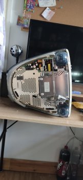
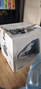
Made a start, made a mess. Can't leave projects out atm. Got the mobo out looks like I'm running the 400Mhz model. Got the mobo out the system looks like someone has been in before me and made a bit of a mess with broken clips inside.
 

Attachments

  • IMG_20200301_152154.jpg
    IMG_20200301_152154.jpg
    254.6 KB · Views: 114
  • IMG_20200301_152204.jpg
    IMG_20200301_152204.jpg
    273.7 KB · Views: 108
  • IMG_20200301_152217.jpg
    IMG_20200301_152217.jpg
    228.5 KB · Views: 98

rockyhill

macrumors regular
Dec 24, 2016
214
67
Miami Fl, United States
Does anyone have a slot loader that still boots? Mine do not so I can't do what I need.

Here is my problem. In order to correctly configure the video resolution, the video source, my regular computer,
requests an EDID from a connected monitor, in this case the iMac G3.
The EDID holds the parameters that tell the source how to correctly display video on the connected monitor.
To date, I've been using EDID's that I've manually created or created by using a modeline grabbed from the internet.

I think the issues I'm having in trying to get both the init sequence and EDID configuration on a single chip
are due to a poorly constructed EDID, specifically the part describing 1024x768 @ 75Hz.
I think that if I had the original Apple EDID things would work allowing me to build the adapter board using only a single atmega 328p .

So, does anyone have a working slot loader(a tray loader might work as well.) that can be used to extract the EDID?
I'm not sure how one could do that booting into OSX but I know it's possible because it's
been done before. It was shared with me and I hand copied the hex code and it worked.
eMac EDID HEX code

The other way one could do it is to burn an ubuntu image onto a CD and boot a live image on the iMac, no need to install.
After that it's a simple matter of running a couple of commands and one could copy the original EDID info.
get the iso
lubuntu 16.04 for powerpc macs

install edid tools and use them (in memory not on HD unless you want to)
Using "get-edid"

Fingers crossed.

Thanks in advance.
[automerge]1583078137[/automerge]
Made a start, made a mess. Can't leave projects out atm. Got the mobo out looks like I'm running the 400Mhz model. Got the mobo out the system looks like someone has been in before me and made a bit of a mess with broken clips inside.

Excited to see your progress! I hope your inner bezel doesn't shatter like mine did they are so brittle.
Good luck!
 

DrJekyll_XYZ

macrumors member
Feb 12, 2020
34
0
Made a start, made a mess. Can't leave projects out atm. Got the mobo out looks like I'm running the 400Mhz model. Got the mobo out the system looks like someone has been in before me and made a bit of a mess with broken clips inside.

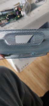
There's a space on the rear of the mesh for a VGA connector on my iMac, great place to put an external VGA connector.

Maybe it's best just to leave a header so it can be connected later for audio?

Also check out IDC 20 connectors and headers. Might match the J20 connector
[automerge]1583096317[/automerge]
Also my system works but I'll have to put the motherboard back in to get the edid. If nobody has done it by the time I can get round to it I'll connect it back up
 

rockyhill

macrumors regular
Dec 24, 2016
214
67
Miami Fl, United States
There's a space on the rear of the mesh for a VGA connector on my iMac, great place to put an external VGA connector.

Maybe it's best just to leave a header so it can be connected later for audio?

Also check out IDC 20 connectors and headers. Might match the J20 connector
[automerge]1583096317[/automerge]
Also my system works but I'll have to put the motherboard back in to get the edid. If nobody has done it by the time I can get round to it I'll connect it back up

Do you mean have a VGA connector coming out of the back to use as an input or to have as an output for a second monitor?
As an input we could do something like a female to female board where one has the option of connecting the J20 board to it with a short VGA cable if the computer is going to be external.

As an audio out would be nice as well, a clean way of connecting external speakers perhaps?

IDC connectors seem to be the right pitch so they should mate. I ordered a pair of 2-walled connectors 20 and 26 pin.
They did mate and I did make them fit eventually but the plastic wall broke... maybe a bare header is the best bet. I have a
handful of raspberry pi headers left over that are a good match and they are made to be trimmed to size. I'll try with
those since I already have them.

I had some time so I made some more changes to the board to make it fit a little better. It turns out a rectangular board
will not fit. If you can get the edid and I can make it work with one chip that would make things much nicer.

I'm pretty busy the next couple of weeks but I hope to buckle down and decide on a final design for rev1 and order them by the 12th or so.


Screenshot from 2020-03-01 22-57-55.png


Screenshot from 2020-03-01 22-57-28.png
Screenshot from 2020-03-01 22-56-52.png
 

DrJekyll_XYZ

macrumors member
Feb 12, 2020
34
0
Do you mean have a VGA connector coming out of the back to use as an input or to have as an output for a second monitor?
As an input we could do something like a female to female board where one has the option of connecting the J20 board to it with a short VGA cable if the computer is going to be external.

As an audio out would be nice as well, a clean way of connecting external speakers perhaps?

IDC connectors seem to be the right pitch so they should mate. I ordered a pair of 2-walled connectors 20 and 26 pin.
They did mate and I did make them fit eventually but the plastic wall broke... maybe a bare header is the best bet. I have a
handful of raspberry pi headers left over that are a good match and they are made to be trimmed to size. I'll try with
those since I already have them.

I had some time so I made some more changes to the board to make it fit a little better. It turns out a rectangular board
will not fit. If you can get the edid and I can make it work with one chip that would make things much nicer.

I'm pretty busy the next couple of weeks but I hope to buckle down and decide on a final design for rev1 and order them by the 12th or so.


View attachment 897001


View attachment 897002 View attachment 897003

It was used for VGA output and sits behind a plastic panel on the DV g3 models, it literally sits at the back most point if the RF shielding at the end of the mobo. I'll take some better pictures maybe find some mounting holes near the rear.

That's looking very very nice my friend. Very professional.

I'll get the edid.
 

DrJekyll_XYZ

macrumors member
Feb 12, 2020
34
0
So I put the board back in took some pictures of the VGA for reference. Burnt lubuntu to a dvd (mines a dvd tom version) got it to boot to yaboot but couldn't get into usable Linux. Tried a copy of mintppc and got it installed and it just broke, the apt command didn't work, no interface no nothing. Realised I can do a pendrive so did mintppc and no success... There goes 4 hours of OS installs (old mac is slow)... I put lubuntu onto a pendrive and I will try again tonight.

IMG_20200304_191611.jpg
IMG_20200304_192408.jpg
IMG_20200304_215113.jpg


Pain In the rear
 

rockyhill

macrumors regular
Dec 24, 2016
214
67
Miami Fl, United States
Yes, Linux installs can be a tremendous pain in the rear! I think I saw a video where one guy installed xubuntu.....
Thanks for trying and thanks for the pics!

I think you'll get it to boot.

I see there is a mounting hole next to the adapter, I've never noticed. This is a perfect place to mount some sort of adapter board(s). Have several types for HDMI out/in or VGA out/in or audio out/in.
 

crozone

macrumors newbie
Feb 24, 2020
5
0
Australia
I got Lubuntu 16.04 booting by burning lubuntu-16.04-desktop-powerpc.iso with ImgBurn, and then running the recommended install. The installer is a pain to get working if you use the manual partitioning approach, I couldn't figure out how to get it to set up the OpenFirmware boot partition correctly. I opted to just let it do its thing with the hands off recommended install, and then manually cleaned up the partitions after.

Note, if you have an OS 9 install, the Linux partitioning utilities will kill the hidden "Apple_Driver" partitions which OS 9 requires to boot. You'll need to boot into an OS 9 install disk and load up Disk Utility. Then from the top menu bar, select "Update Drivers" or similar. It'll rewrite the OS 9 driver partitions and fix OS 9.
 

rockyhill

macrumors regular
Dec 24, 2016
214
67
Miami Fl, United States
I finally ordered a batch of three rev-1 video-on/off boards..... I hope it works.

Anyhow I added a link to the shared project on the github for this.

https://github.com/qbancoffee/imac_g3_ivad_board_init

Scroll down and click on the link and you can see it. I plan on adding the other boards as I make them.
Rev-1's almost have issues so lets see.

Fingers crossed........
[automerge]1583453308[/automerge]
Oh Yeah, this is how they should look when built, except the boards will be purple.
Screenshot from 2020-03-05 19-05-20.png
Screenshot from 2020-03-05 19-05-42.png
Screenshot from 2020-03-05 19-06-13.png
 
Last edited:

rockyhill

macrumors regular
Dec 24, 2016
214
67
Miami Fl, United States
It was used for VGA output and sits behind a plastic panel on the DV g3 models, it literally sits at the back most point if the RF shielding at the end of the mobo. I'll take some better pictures maybe find some mounting holes near the rear.

That's looking very very nice my friend. Very professional.

I'll get the edid.


Thanks! I hope it works the first time around though. Although I am hoping to eventually get rid of one of the chips.
[automerge]1583479226[/automerge]
Looks fantastic!

Thanks!
 

DrJekyll_XYZ

macrumors member
Feb 12, 2020
34
0
IMG_20200306_093505.jpg
IMG_20200306_092832.jpg


So I have got myself prepared for some more attempts... No messing around.

Also rummaged in the hard drive bin at work this morning and found a 40gb Ultra ATA HDD, the errors I've been getting and the sounds it's been making is making me think HDD errors lots of SDA issues. If not no worries free upgrade.

It shouldn't be this hard to install Linux... I get it to attempt to boot but it just freezes when I try to run a live session... May go full install route.

I got Lubuntu 16.04 booting by burning lubuntu-16.04-desktop-powerpc.iso with ImgBurn, and then running the recommended install. The installer is a pain to get working if you use the manual partitioning approach, I couldn't figure out how to get it to set up the OpenFirmware boot partition correctly. I opted to just let it do its thing with the hands off recommended install, and then manually cleaned up the partitions after.

Note, if you have an OS 9 install, the Linux partitioning utilities will kill the hidden "Apple_Driver" partitions which OS 9 requires to boot. You'll need to boot into an OS 9 install disk and load up Disk Utility. Then from the top menu bar, select "Update Drivers" or similar. It'll rewrite the OS 9 driver partitions and fix OS 9.

Are you saying install Linux automatically then when it's done use the OS 9 disk to repair the driver partition with the apple drivers and that makes it work?
 

rockyhill

macrumors regular
Dec 24, 2016
214
67
Miami Fl, United States
Okay got Linux on yay... Bad news, no edid... View attachment 897866

That's terrible news but all is not lost. I think the iVad board uses address 0x53 instead of 0x50.
I can't help you for the next several days but this might be a "simple" matter of downloading the source
, changing the address , recompiling , installing and then trying again.

first you have to enable sources in ubuntu in the update software dialog and refresh.
then type the following

sudo apt-get purge read-edid
apt-get source read-edid
sudo apt-get build-dep read-edid
cd read-edid-3.0.2 (or whatever version you downloaded )
cd get-edid
nano i2c.c (you can use any text editor your comfortable with im using nano but I think lubuntu has leafpad)

find the line that has 0x50 and change it to 0x53 and save (ctrl-x in nano)

cd ..
mkdir build
cd build
cmake ../
make
sudo make install


you should have a modified version of red-edid that looks on 0x53

good luck
 

Spanky Deluxe

macrumors demi-god
Mar 17, 2005
5,285
1,789
London, UK
Really nice to see the progress going on in here lately. I'm performing an iMac mod at the moment myself - something I've been planning to do for about ten years since I picked up a gorgeous Ruby iMac at a car boot sale. I've decided to get rid of the CRT for my one although I'm planning on making use of the existing speakers and mic if possible so the info in here will still be invaluable. My project should be much simpler, in theory as it's just using the iMac G3 as a case really and there's *loads* of room for something like that.

I took a nice step forward today with fitting the LCD. It's a test fit for now but I think it'll likely be ok as it is. Photo of it in place attached. Nothing is screwed and all the plastic is just resting there and there's lots more to do.

It's powered by a 2012 i7 Mac Mini. I'm not planning on modding the mini in any way as I want it to be upgradeable easily with newer minis down the line. This does mean that I can't use the power button and will need to set it to auto start up after power loss and position it in such a way that if I need to power it on manually, I can insert a long pokey thing in the right way to hit the power button. I plan to connect as much stuff as possible to the original side panel (just hot gluing extension cables) and will try to connect up the speakers, microphone and headphone jacks too. I've got a blu-ray drive that I'm hoping will fit in the original optical bay too. I'll probably connect the front power button to the display controller's power switch (don't mind soldering onto that) and the little mini buttons on the original side panel to the input select button on that board because I'd like to get it all configured in such a way that I can also use the display as a display for something else e.g. some other retro hardware like maybe my old GameCube or an Amiga. I'll likely use the VGA connector on the back for that (SCART->VGA) but that's a little down the road yet. First things first will be to get this all put together. I don't have a huge amount of time to spend on this project so I'm prioritising 'getting it done well enough' over 'getting it done perfectly'!
 

Attachments

  • IMG_2761.jpeg
    IMG_2761.jpeg
    441.6 KB · Views: 250

DrJekyll_XYZ

macrumors member
Feb 12, 2020
34
0
Really nice to see the progress going on in here lately. I'm performing an iMac mod at the moment myself - something I've been planning to do for about ten years since I picked up a gorgeous Ruby iMac at a car boot sale. I've decided to get rid of the CRT for my one although I'm planning on making use of the existing speakers and mic if possible so the info in here will still be invaluable. My project should be much simpler, in theory as it's just using the iMac G3 as a case really and there's *loads* of room for something like that.

I took a nice step forward today with fitting the LCD. It's a test fit for now but I think it'll likely be ok as it is. Photo of it in place attached. Nothing is screwed and all the plastic is just resting there and there's lots more to do.

It's powered by a 2012 i7 Mac Mini. I'm not planning on modding the mini in any way as I want it to be upgradeable easily with newer minis down the line. This does mean that I can't use the power button and will need to set it to auto start up after power loss and position it in such a way that if I need to power it on manually, I can insert a long pokey thing in the right way to hit the power button. I plan to connect as much stuff as possible to the original side panel (just hot gluing extension cables) and will try to connect up the speakers, microphone and headphone jacks too. I've got a blu-ray drive that I'm hoping will fit in the original optical bay too. I'll probably connect the front power button to the display controller's power switch (don't mind soldering onto that) and the little mini buttons on the original side panel to the input select button on that board because I'd like to get it all configured in such a way that I can also use the display as a display for something else e.g. some other retro hardware like maybe my old GameCube or an Amiga. I'll likely use the VGA connector on the back for that (SCART->VGA) but that's a little down the road yet. First things first will be to get this all put together. I don't have a huge amount of time to spend on this project so I'm prioritising 'getting it done well enough' over 'getting it done perfectly'!

Sacrilege!!!!

Seriously though I think wiring up the ports is a great idea all the pinout is available on rockyhills GitHub loads of info on there, should help you isolate which connectors you need for what port.

It looks good with that LCD wish you luck
 

DrJekyll_XYZ

macrumors member
Feb 12, 2020
34
0
That's terrible news but all is not lost. I think the iVad board uses address 0x53 instead of 0x50.
I can't help you for the next several days but this might be a "simple" matter of downloading the source
, changing the address , recompiling , installing and then trying again.

first you have to enable sources in ubuntu in the update software dialog and refresh.
then type the following

sudo apt-get purge read-edid
apt-get source read-edid
sudo apt-get build-dep read-edid
cd read-edid-3.0.2 (or whatever version you downloaded )
cd get-edid
nano i2c.c (you can use any text editor your comfortable with im using nano but I think lubuntu has leafpad)

find the line that has 0x50 and change it to 0x53 and save (ctrl-x in nano)

cd ..
mkdir build
cd build
cmake ../
make
sudo make install


you should have a modified version of red-edid that looks on 0x53

good luck

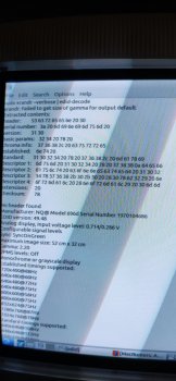
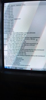
No dice with that. Nothing on 50 51 52 53 or 54
...

I tried xrandr instead and got something but not sure how useable it is...

It's not letting me upload from the iMac...
 

Attachments

  • IMG_20200310_001642.jpg
    IMG_20200310_001642.jpg
    456.3 KB · Views: 105
  • IMG_20200310_001659.jpg
    IMG_20200310_001659.jpg
    493.2 KB · Views: 122

rockyhill

macrumors regular
Dec 24, 2016
214
67
Miami Fl, United States
No dice with that. Nothing on 50 51 52 53 or 54
...

I tried xrandr instead and got something but not sure how useable it is...

It's not letting me upload from the iMac...

I didn't think about using xrandr , that's a good idea! I did a quick google search after seeing your post and it looks like you can issue
Code:
xrandr --props

and you'll get edid info.
[automerge]1583800416[/automerge]
Really nice to see the progress going on in here lately. I'm performing an iMac mod at the moment myself - something I've been planning to do for about ten years since I picked up a gorgeous Ruby iMac at a car boot sale. I've decided to get rid of the CRT for my one although I'm planning on making use of the existing speakers and mic if possible so the info in here will still be invaluable. My project should be much simpler, in theory as it's just using the iMac G3 as a case really and there's *loads* of room for something like that.

I took a nice step forward today with fitting the LCD. It's a test fit for now but I think it'll likely be ok as it is. Photo of it in place attached. Nothing is screwed and all the plastic is just resting there and there's lots more to do.

It's powered by a 2012 i7 Mac Mini. I'm not planning on modding the mini in any way as I want it to be upgradeable easily with newer minis down the line. This does mean that I can't use the power button and will need to set it to auto start up after power loss and position it in such a way that if I need to power it on manually, I can insert a long pokey thing in the right way to hit the power button. I plan to connect as much stuff as possible to the original side panel (just hot gluing extension cables) and will try to connect up the speakers, microphone and headphone jacks too. I've got a blu-ray drive that I'm hoping will fit in the original optical bay too. I'll probably connect the front power button to the display controller's power switch (don't mind soldering onto that) and the little mini buttons on the original side panel to the input select button on that board because I'd like to get it all configured in such a way that I can also use the display as a display for something else e.g. some other retro hardware like maybe my old GameCube or an Amiga. I'll likely use the VGA connector on the back for that (SCART->VGA) but that's a little down the road yet. First things first will be to get this all put together. I don't have a huge amount of time to spend on this project so I'm prioritising 'getting it done well enough' over 'getting it done perfectly'!


I'm a CRT fan but I have admit that it looks really nice!
[automerge]1583800757[/automerge]
No dice with that. Nothing on 50 51 52 53 or 54
...

I tried xrandr instead and got something but not sure how useable it is...

It's not letting me upload from the iMac...
Actually

Code:
xrandr --verbose

Like you already used should get it all.
Send it to a text file and post that. I'll dig through it and grab the edid info.

Code:
xrandr --verbose > edid.txt
[automerge]1583801059[/automerge]
No dice with that. Nothing on 50 51 52 53 or 54
...

I tried xrandr instead and got something but not sure how useable it is...

It's not letting me upload from the iMac...
Actually

Code:
xrandr --verbose

Like you already used should get it all.
Send it to a text file and post that. I'll dig through it and grab the edid info.

Code:
xrandr --verbose > edid.txt
[automerge]1583801189[/automerge]
No dice with that. Nothing on 50 51 52 53 or 54
...

I tried xrandr instead and got something but not sure how useable it is...

It's not letting me upload from the iMac...

Sorry, I missed the part that you can't upload from the iMac .. that is odd. Maybe there is a minimum version requirement for the
web browser on macrumors?
 
Last edited:

Spanky Deluxe

macrumors demi-god
Mar 17, 2005
5,285
1,789
London, UK
Rockyhill, your pinout diagrams were a real help today! In short order, I managed to jerry rig the front switch, power led and both side panel switches to my display panel driver board. Furthermore, while doing so, I happened to notice a header on the board that said 'speakers'. I looked up the manual for the board and in it it said "Audio Output: 2×1W(8Ω)", which didn't sound like a line out to me so I connected the audio pins of the speakers from the main iMac socket and hey presto, they work! Turns out I don't need to worry about the audio amplifiers I ordered after all! I do need to find a workaround for changing HDMI audio, I think I can do something with Soundflower. The one thing I didn't have much luck with today was the microphone. I just tried wiring the black+red+white to the corresponding cables of a 3.5mm stereo cable but alas, nothing. It might be that the red wire is actually +5V or something seeing as most mono microphones don't require three cables.
 
Register on MacRumors! This sidebar will go away, and you'll see fewer ads.