Become a MacRumors Supporter for $50/year with no ads, ability to filter front page stories, and private forums.

rockyhill

macrumors regular
Dec 24, 2016
214
67
Miami Fl, United States
Rockyhill, your pinout diagrams were a real help today! In short order, I managed to jerry rig the front switch, power led and both side panel switches to my display panel driver board. Furthermore, while doing so, I happened to notice a header on the board that said 'speakers'. I looked up the manual for the board and in it it said "Audio Output: 2×1W(8Ω)", which didn't sound like a line out to me so I connected the audio pins of the speakers from the main iMac socket and hey presto, they work! Turns out I don't need to worry about the audio amplifiers I ordered after all! I do need to find a workaround for changing HDMI audio, I think I can do something with Soundflower. The one thing I didn't have much luck with today was the microphone. I just tried wiring the black+red+white to the corresponding cables of a 3.5mm stereo cable but alas, nothing. It might be that the red wire is actually +5V or something seeing as most mono microphones don't require three cables.

I'm glad they helped!

I haven't updated the pinouts yet but I did some more probing and I followed the 3 wires to the mic. Turns out that you only need the
red and white wires, the black is just shielding. I imagine you need the shielding since it wraps around the CRT.
In my case when I finally wire up the mic, I'll connect the black wire to ground.

Do you have pics/video of your progress? I would love to see/hear it.

Good luck with the mic, it sound like you'll get it soon.
 

Spanky Deluxe

macrumors demi-god
Mar 17, 2005
5,285
1,789
London, UK
I'm glad they helped!

I haven't updated the pinouts yet but I did some more probing and I followed the 3 wires to the mic. Turns out that you only need the
red and white wires, the black is just shielding. I imagine you need the shielding since it wraps around the CRT.
In my case when I finally wire up the mic, I'll connect the black wire to ground.

Do you have pics/video of your progress? I would love to see/hear it.

Good luck with the mic, it sound like you'll get it soon.

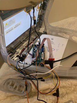
It's *very* ghetto right now. Here's the insides as it is. Nothing apart from the screen is mounted yet!

I tried the mic pins a few different ways but couldn't get anything. It might be that I need to get a usb sound capture device with a mic in as I think the input on the mac is a line in, which might mean it's not sensitive enough.

Still to do: Mount *everything*, install a kettle lead socket connected to a uk multiway socket inside, take out the old optical drive and completely disassemble it, using it as a frame for my new optical drive, fix the mic and then mount short extension cables to the side panel and lastly, clean and polish the plastics lots as it's quite scuffed. Most of what I need to do is simple mounting (plastic mould stuff), bit of hot glue and a very small amount of soldering. It's just the mic and the optical drive which will be a bit of a pain (in theory). Using it as an external display for other devices will come later.
 

Attachments

  • IMG_2765.jpeg
    IMG_2765.jpeg
    463.3 KB · Views: 146

rockyhill

macrumors regular
Dec 24, 2016
214
67
Miami Fl, United States
It's *very* ghetto right now. Here's the insides as it is. Nothing apart from the screen is mounted yet!

I tried the mic pins a few different ways but couldn't get anything. It might be that I need to get a usb sound capture device with a mic in as I think the input on the mac is a line in, which might mean it's not sensitive enough.

Still to do: Mount *everything*, install a kettle lead socket connected to a uk multiway socket inside, take out the old optical drive and completely disassemble it, using it as a frame for my new optical drive, fix the mic and then mount short extension cables to the side panel and lastly, clean and polish the plastics lots as it's quite scuffed. Most of what I need to do is simple mounting (plastic mould stuff), bit of hot glue and a very small amount of soldering. It's just the mic and the optical drive which will be a bit of a pain (in theory). Using it as an external display for other devices will come later.

Looks great, I recently bought a similar board for a display I had laying around but it wasn't compatible.
So you're going to mount an optical drive? The mac mini will be open then?
 

DrJekyll_XYZ

macrumors member
Feb 12, 2020
34
0
Good News. Got the darn thing onto a laptop... used xrandr --verbose and it gives you very little. Use sudo xrandr --verbose | decode-edid and you get the text file attached.

Is that of any use to you mister hill
 

Attachments

  • edid.txt
    2.2 KB · Views: 119

rockyhill

macrumors regular
Dec 24, 2016
214
67
Miami Fl, United States
Good News. Got the darn thing onto a laptop... used xrandr --verbose and it gives you very little. Use sudo xrandr --verbose | decode-edid and you get the text file attached.

Is that of any use to you mister hill
Great!, I Think I see some good info in there. It might take me a while but I think I can do something with this.
Thanks!
 

Spanky Deluxe

macrumors demi-god
Mar 17, 2005
5,285
1,789
London, UK
Looks great, I recently bought a similar board for a display I had laying around but it wasn't compatible.
So you're going to mount an optical drive? The mac mini will be open then?

Yeah, I got the board specifically for this display (which was also bought specifically for this project) and it's working great! I do plan to mount an optical drive but it'll be connected to the Mac Mini with USB. I've got an optical USB3 caddy that I'm going to disassemble and use the guts from to connect it so that should be pretty simple - mounting it will be the harder part.
 

rockyhill

macrumors regular
Dec 24, 2016
214
67
Miami Fl, United States
Good News. Got the darn thing onto a laptop... used xrandr --verbose and it gives you very little. Use sudo xrandr --verbose | decode-edid and you get the text file attached.

Is that of any use to you mister hill


Can you check and see if you can indeed change the resolution to the Established timings as reported
in the file you sent?

Established timings supported:
720x400@88Hz
640x480@60Hz
640x480@72Hz
640x480@75Hz
800x600@56Hz
800x600@75Hz
832x624@75Hz
1280x768@87Hz
1024x768@70Hz
 

DrJekyll_XYZ

macrumors member
Feb 12, 2020
34
0
it pops back with Size (insert size here) not found in available modes.

Trying it with the GUI gives me the option of 1024x768@75Hz or auto which auto selects 1024x768@75Hz. I think we are mostly locked to the one resolution.
 

rockyhill

macrumors regular
Dec 24, 2016
214
67
Miami Fl, United States
Can you check and see if you can indeed change the resolution to the Established timings as reported
in the file you sent?
it pops back with Size (insert size here) not found in available modes.

Trying it with the GUI gives me the option of 1024x768@75Hz or auto which auto selects 1024x768@75Hz. I think we are mostly locked to the one resolution.

I looked through the file for a couple of hours but unfortunately it was mostly nonsense. However, it gave me insight and I was able to
use it to generate an edid that works with two resolutions, 1024x768 and 800x600.


I think I'm getting the hang of producing an EDID now. Thanks for the hard work!

Tomorrow I'll post what I have so far.
 

Spanky Deluxe

macrumors demi-god
Mar 17, 2005
5,285
1,789
London, UK
I haven't updated the pinouts yet but I did some more probing and I followed the 3 wires to the mic. Turns out that you only need the
red and white wires, the black is just shielding. I imagine you need the shielding since it wraps around the CRT.
In my case when I finally wire up the mic, I'll connect the black wire to ground.

I tried the mic with a cheap USB sound card that I got delivered last night and it works! Another piece of the jigsaw slots in! I think that's all the electrical puzzles now solved. It's now just the physical stuff to sort out - mounting it all in a decent way, hacking the optical drive in there (electrically it's just USB so it'll work), glueing together the in/out ports on the side and mounting the power connector, which isn't due to arrive for a few days.

The one thing that's eluded me in all this though is a way to extend the power button of the mac mini without hacking into it. I would have thought that there'd be *something* already available out there that's designed for extending a push button i.e. just an actuator that you can stick over a power button connected by cable to a push button but alas, I haven't found anything. There are some smart remote push button things that require an app to use but that's way too complicated.
 

rockyhill

macrumors regular
Dec 24, 2016
214
67
Miami Fl, United States
I tried the mic with a cheap USB sound card that I got delivered last night and it works! Another piece of the jigsaw slots in! I think that's all the electrical puzzles now solved. It's now just the physical stuff to sort out - mounting it all in a decent way, hacking the optical drive in there (electrically it's just USB so it'll work), glueing together the in/out ports on the side and mounting the power connector, which isn't due to arrive for a few days.

The one thing that's eluded me in all this though is a way to extend the power button of the mac mini without hacking into it. I would have thought that there'd be *something* already available out there that's designed for extending a push button i.e. just an actuator that you can stick over a power button connected by cable to a push button but alas, I haven't found anything. There are some smart remote push button things that require an app to use but that's way too complicated.

Great progress. I can't wait to see your build!

I haven't seen an actuator like that but have you considered using Wake On Lan (WOL)?
I don't know if your mac mini is is WOL enabled but if it is maybe you can hack something together. Say an arduino wired to the power button that sends the WOL packets to the ethernet card that will tell the computer to boot.

Might be possible....... A WOL switch might exist, I dunno. Maybe something was just invented here....


Adding this after some duck-duck-going,

Looks like someone has already done it !

https://www.megunolink.com/download/libraries/wake-on-lan/

https://playground.arduino.cc/Main/ArduinoWaker/

I guess you would need to enable Wol on the mac mini, purchase an arduino, an arduino Ethernet shield, and possibly
a two port Ethernet switch so that you don't lose the mac mini's Ethernet port.

The write up claims you can power on and power off a Wol enabled computer with this.
 
Last edited:

Spanky Deluxe

macrumors demi-god
Mar 17, 2005
5,285
1,789
London, UK
Great progress. I can't wait to see your build!

I haven't seen an actuator like that but have you considered using Wake On Lan (WOL)?
I don't know if your mac mini is is WOL enabled but if it is maybe you can hack something together. Say an arduino wired to the power button that sends the WOL packets to the ethernet card that will tell the computer to boot.

Might be possible....... A WOL switch might exist, I dunno. Maybe something was just invented here....


Adding this after some duck-duck-going,

Looks like someone has already done it !

https://www.megunolink.com/download/libraries/wake-on-lan/

https://playground.arduino.cc/Main/ArduinoWaker/

I guess you would need to enable Wol on the mac mini, purchase an arduino, an arduino Ethernet shield, and possibly
a two port Ethernet switch so that you don't lose the mac mini's Ethernet port.

The write up claims you can power on and power off a Wol enabled computer with this.

That's an interesting idea! It would mean losing the ethernet port though unless I built in an ethernet hub. Here's the mobile app enabled button: https://www.amazon.co.uk/SwitchBot-Smart-Switch-Button-Pusher/dp/B07B7NXV4R
I could maybe just go with this route for ease as it's pretty cheap and the computer will be set to always be on and to restart after a power loss. A keyboard tap or mouse click should wake it from sleep just fine anyway. I think I could build a little arduino controlled circuit with a nano board or something to control an actuator without too much difficulty but I'll likely delay that for a later date.

Edit: I just ordered the smart switch as well as an actuator so I can set up a solution for now and have the stuff ready for a future arduino controlled solution. :D
 

rockyhill

macrumors regular
Dec 24, 2016
214
67
Miami Fl, United States
That's an interesting idea! It would mean losing the ethernet port though unless I built in an ethernet hub. Here's the mobile app enabled button: https://www.amazon.co.uk/SwitchBot-Smart-Switch-Button-Pusher/dp/B07B7NXV4R
I could maybe just go with this route for ease as it's pretty cheap and the computer will be set to always be on and to restart after a power loss. A keyboard tap or mouse click should wake it from sleep just fine anyway. I think I could build a little arduino controlled circuit with a nano board or something to control an actuator without too much difficulty but I'll likely delay that for a later date.

Edit: I just ordered the smart switch as well as an actuator so I can set up a solution for now and have the stuff ready for a future arduino controlled solution. :D


Oh my God, that's a kooky video, it's very comical and it kind of reminds of the Most Useless Machine Ever except it's actually useful.

I had no idea that existed, I think I'll order one.
 

Raging Dufus

macrumors 6502a
Aug 2, 2018
634
1,171
Kansas USA
This probably takes the fun out of it, but before you guys go all Rube Goldberg to find a way to start the iMac, maybe consider an original iMac keyboard? [MODS: not my auction!] Take a look at the pics, they have a power button built right into the keyboard, and come in colors to match your iMac. If you connected the USB cable from the keyboard to a USB port (assuming it has one) on your display controller, then you can just press the button on the keyboard to turn the thing on.

I've got one of these keyboards, and it turns on (and off) any Mac I've ever plugged it into. Apple stopped providing power buttons on USB keyboards after discontinuing the iMac G3 line because it was a nonstandard application of USB; the USB consortium might have pressured them into dropping it, I don't know.

Just a thought. In any event, really cool project!
 

rockyhill

macrumors regular
Dec 24, 2016
214
67
Miami Fl, United States
If you put a mobo in and use the HD AC97 header that has both input and output. you can wire them to the ports on the front. Im not sure how to wire the sense so that the mobo would detect that you plugged in headphones and disable the audio to the speaker amplifier.

You could simply add a bluetooth module to the amplifier and use your phone or a usb bluetooth dongle or built BT in then you wouldnt even need the ports at the front except to wire into the HD AC97 header with sense allowing the system to detect the new input/output.

Simply connecting the speakers to an amp and giving the option for 3.5mm connection opens a lot of doors for how people can connect whatever device theyre planning on cramming inside.

I found a schematic of the amp. it uses the PAM8403 amp chip:

View attachment 896578
[automerge]1582908903[/automerge]
Most modern PC's have both of these. Wire the inbuilt mic to the AC97 header for simplicity and compatibility. Then the ports on the front to the HDA connector and you may be able to get some decent quality from modern devices.

View attachment 896580


Here is a video showing off the PAM8403. Great choice. I have to work on the noise being picked up but I think that's
going be a simple matter of using a shielded cable.

[automerge]1584055617[/automerge]
This probably takes the fun out of it, but before you guys go all Rube Goldberg to find a way to start the iMac, maybe consider an original iMac keyboard? [MODS: not my auction!] Take a look at the pics, they have a power button built right into the keyboard, and come in colors to match your iMac. If you connected the USB cable from the keyboard to a USB port (assuming it has one) on your display controller, then you can just press the button on the keyboard to turn the thing on.

I've got one of these keyboards, and it turns on (and off) any Mac I've ever plugged it into. Apple stopped providing power buttons on USB keyboards after discontinuing the iMac G3 line because it was a nonstandard application of USB; the USB consortium might have pressured them into dropping it, I don't know.

Just a thought. In any event, really cool project!

That's a good point. it might be as simple as enabling wake on USB in the bios.....
 
Last edited:
  • Like
Reactions: Raging Dufus

DrJekyll_XYZ

macrumors member
Feb 12, 2020
34
0
Here is a video showing off the PAM8403. Great choice. I have to work on the noise being picked up but I think that's
going be a simple matter of using a shielded cable.

[automerge]1584055617[/automerge]


That's a good point. it might be as simple as enabling wake on USB in the bios.....

Sounds good so far. Great little amp and yeah you're probably getting cross talk with the cable proximity and lack of shielding. I remember a phone system with so many unshielded cables that you could hear the radio over the phone calls. Buzz is probably just because it's close to the power cable.

If you're going that far there is usually an option in bios that lets you boot when power is supplied to the system. I know many of the servers I work on have it. No need to mess with WOL or magic packet as it's so flakey I've had nothing but issues with it over the years.

There's an option in the Mac energy saving setting in osx that's a tick box that says restart after power outage which "should" boot when power is applied. Maybe we can avoid a rube Goldberg machine.

Gimme a shout if you need anything
 

Spanky Deluxe

macrumors demi-god
Mar 17, 2005
5,285
1,789
London, UK
This probably takes the fun out of it, but before you guys go all Rube Goldberg to find a way to start the iMac, maybe consider an original iMac keyboard? [MODS: not my auction!] Take a look at the pics, they have a power button built right into the keyboard, and come in colors to match your iMac. If you connected the USB cable from the keyboard to a USB port (assuming it has one) on your display controller, then you can just press the button on the keyboard to turn the thing on.

I've got one of these keyboards, and it turns on (and off) any Mac I've ever plugged it into. Apple stopped providing power buttons on USB keyboards after discontinuing the iMac G3 line because it was a nonstandard application of USB; the USB consortium might have pressured them into dropping it, I don't know.

Just a thought. In any event, really cool project!

That could be an idea. This mac (Ruby Red iMac) originally came with a Pro Keyboard and Pro Mouse. I've still got the mouse but haven't been able to find my keyboard - think it may have been lost in the process of moving a few times since I got the machine. If I can't find it, maybe I'll pick up a graphite iMac G3 keyboard with the power button.
[automerge]1584115471[/automerge]
Here is a video showing off the PAM8403. Great choice. I have to work on the noise being picked up but I think that's
going be a simple matter of using a shielded cable.


That sounds great!
 
  • Like
Reactions: Raging Dufus

DrJekyll_XYZ

macrumors member
Feb 12, 2020
34
0
So I finished and ordered the J22 adapter board. Here are some pics.

BTW both board designs are in the github repo if anyone is interested.

View attachment 899155 View attachment 899156 View attachment 899157

Dumb question. This new board is to allow you to connect the onboard switch to a pc and the onboard speakers to the amp?

It doesn't allow you to connect the headphone ports on the front to anything?

The board looks good just asking to understand. Have you had any joy getting the edid and init on one chip?
 

rockyhill

macrumors regular
Dec 24, 2016
214
67
Miami Fl, United States
Dumb question. This new board is to allow you to connect the onboard switch to a pc and the onboard speakers to the amp?

It doesn't allow you to connect the headphone ports on the front to anything?

The board looks good just asking to understand. Have you had any joy getting the edid and init on one chip?

So I had some trouble getting this board designed because I don't have enough information to make
it elegant-ish....

-Power button
The idea is to run a wire from the button terminal on this board to the matching button terminal on the J20 board
to turn the CRT on. The button shorts the input to ground so in theory one could splice one side of a button connector
on a mother board to here and it will turn on.

-Speakers
These are just breakouts to the speakers. You can choose your amp and wire into these terminals.

-Headphones
The headphone come out to the 2x3 pin header near the mounting hole. This is where I had issues.
There is a sense circuit that needs to be made so that when one plugs in a headphone, the amp is disabled
and the audio is routed to the headphone jack. This requires 5 VDC and some simple components.
There is 24 VAC available but it needs to get rectified and dropped to be useful in a sense circuit.
Placing the whole amplifier circuit on this board would solve several issues but unfortunately the PAM8403
doesn't come in a dip package only surface mount. I have experience with surface mount components but not everyone does
so I wanted to make something that people can assemble with little expertise.
I didn't want to omit the headphone connections so I broke them out to a 6 pin connector for people to use.

This is also a rev 1 board and I will likely redesign it with improvements but I wanted something so that I can work
more comfortably because I want to clean up the rats nest of wires I have on my bench right now.
Difficult to work...

No joy yet getting things to work with one chip. I'm planning to do so within the next couple of days.

I just got an email from oshpark that the J20 board has shipped so I should receive it in 2 or three days.
 

DrJekyll_XYZ

macrumors member
Feb 12, 2020
34
0
So I had some trouble getting this board designed because I don't have enough information to make
it elegant-ish....

-Power button
The idea is to run a wire from the button terminal on this board to the matching button terminal on the J20 board
to turn the CRT on. The button shorts the input to ground so in theory one could splice one side of a button connector
on a mother board to here and it will turn on.

-Speakers
These are just breakouts to the speakers. You can choose your amp and wire into these terminals.

-Headphones
The headphone come out to the 2x3 pin header near the mounting hole. This is where I had issues.
There is a sense circuit that needs to be made so that when one plugs in a headphone, the amp is disabled
and the audio is routed to the headphone jack. This requires 5 VDC and some simple components.
There is 24 VAC available but it needs to get rectified and dropped to be useful in a sense circuit.
Placing the whole amplifier circuit on this board would solve several issues but unfortunately the PAM8403
doesn't come in a dip package only surface mount. I have experience with surface mount components but not everyone does
so I wanted to make something that people can assemble with little expertise.
I didn't want to omit the headphone connections so I broke them out to a 6 pin connector for people to use.

This is also a rev 1 board and I will likely redesign it with improvements but I wanted something so that I can work
more comfortably because I want to clean up the rats nest of wires I have on my bench right now.
Difficult to work...

No joy yet getting things to work with one chip. I'm planning to do so within the next couple of days.

I just got an email from oshpark that the J20 board has shipped so I should receive it in 2 or three days.

Excellent I look forward to seeing it in play.

It's a shame the 2 boards can't share resources like the 5V, it would end up really messy running wires back and forth. I think that being able to connect a breakout cable to the board would allow for this. I would expand the board at the rear as there's alot of deadspace at the back and just use a small board at the front the breakout to the main board, that way all your connectors are on the one board at the back. This would solve the problem for sense and power button. I suppose that could be achieved by using a simple right angle gpio connector. Maybe I'm over thinking it. I may take a look at your boards in kicad and see if I can figure the program out, help with the board design element.

You're right I forgot what the H connectors were for :p long day.
 

rockyhill

macrumors regular
Dec 24, 2016
214
67
Miami Fl, United States
Excellent I look forward to seeing it in play.

It's a shame the 2 boards can't share resources like the 5V, it would end up really messy running wires back and forth. I think that being able to connect a breakout cable to the board would allow for this. I would expand the board at the rear as there's alot of deadspace at the back and just use a small board at the front the breakout to the main board, that way all your connectors are on the one board at the back. This would solve the problem for sense and power button. I suppose that could be achieved by using a simple right angle gpio connector. Maybe I'm over thinking it. I may take a look at your boards in kicad and see if I can figure the program out, help with the board design element.

You're right I forgot what the H connectors were for :p long day.

Long days, I've definitely been there, I hear you.....

Running all of the wires to the back is not a bad idea, maybe for the next revision.
 

Spanky Deluxe

macrumors demi-god
Mar 17, 2005
5,285
1,789
London, UK
The Arduino Uno I ordered along with a linear actuator and a kettle lead socket all arrived today. I started looking into how to power the 12V linear actuator from the Arduino before I literally facepalmed at how stupid I was being. I want the actuator to turn on when the front button (push button) is pressed. The actuator works by being on or off. I don't need the Arduino at all, I just need to wire up the push button to a 12v circuit with the actuator. Talk about overthinking something! I think it should work fine for relaying pushing the power button to the Mac Mini itself, it'll just be a matter of positioning it right, which I can only do once I've moulded a mount for the Mac Mini. It should be able to translate things like holding the power button down to force power off etc. The LCD driver board uses a 12V supply so I can just slice into that too.
[automerge]1584400022[/automerge]
 
Register on MacRumors! This sidebar will go away, and you'll see fewer ads.