Become a MacRumors Supporter for $50/year with no ads, ability to filter front page stories, and private forums.
All of the LEDs you saw come on are part of the standby/powerup circuitry. They are always powered any time 28v is plugged in, so seeing them come on immediately is normal. When they went out, this was caused by voltage being removed from the LEDs somewhere. Either a chip they rely on getting damaged, a fuse blowing in the external PSU, or OCP tripping in the external PSU.

The FETs you picture are the high side FETs for the 5v rail. If they failed short D/S, that could have applied 28V to anything on the 5V rail. That could be why the CS5165 smells bad. It is possibly dead, and depending on the status of the high side FETs on the CPU card, it could have damaged the CPU itself as well.

These could have failed for a number of reasons. If a FET was installed backwards, I would expect it to blow nearly the moment it was plugged in. A backwards FET would have also applied 28V to the gate driver and blown the LTC1628; the fact that the green standby LED came on makes me think this is unlikely. It is still possible though depending on the path the power ultimately took and the resistances involved. A FET could have also been damaged by excessive heat during soldering. FETs can generally tolerate a good amount of soldering heat, but all parts do have a max spec for soldering temperature where things could get damaged.

A small ball of solder could have floated off when soldering with paste and shorted something near the LTC1628. If something got shorted around the gate drivers, the FET could have been held open permanently after the controller powered up. There is also a very small chance that you got a defective/damaged FET to begin with or it was damaged by ESD during handling.
 
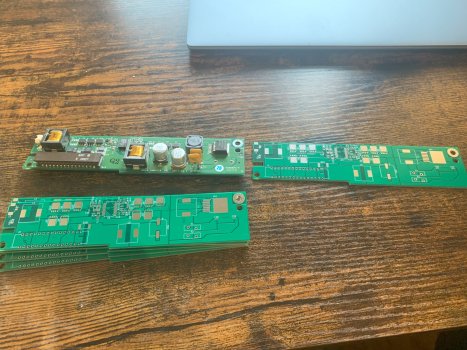
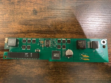
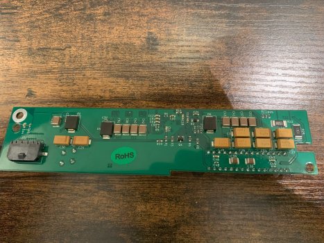
Well this is crazy but I just found this thread because I finished building a 2nd of my own VRM module for a cube as well. I designed it around a year ago but only got around to really putting it together recently and was googling around.
Sorry if I'm hijacking your thread here, but if you want to share ideas, I'd be happy to.
My own conclusions were very similar to yours- improving current capability by increasing the capabilities of the freewheeling diode for the 12V, and in my case using power pad mosfets that are heatsinked to buried copper layers, larger inductors, and larger capacitors for peak power delivery. I'm able to pull 15A with ease on both the 5V and 3V3 rails, even at a 100khz step load with an acceptable amount of ripple.
 

Attachments

  • IMG_4648.jpg
    IMG_4648.jpg
    667.5 KB · Views: 153
  • IMG_4672.jpg
    IMG_4672.jpg
    737.2 KB · Views: 150
  • IMG_4673.jpg
    IMG_4673.jpg
    735.1 KB · Views: 159
Well this is crazy but I just found this thread because I finished building a 2nd of my own VRM module for a cube as well. I designed it around a year ago but only got around to really putting it together recently and was googling around.
Sorry if I'm hijacking your thread here, but if you want to share ideas, I'd be happy to.
My own conclusions were very similar to yours- improving current capability by increasing the capabilities of the freewheeling diode for the 12V, and in my case using power pad mosfets that are heatsinked to buried copper layers, larger inductors, and larger capacitors for peak power delivery. I'm able to pull 15A with ease on both the 5V and 3V3 rails, even at a 100khz step load with an acceptable amount of ripple.
Very nice, I actually have a thread going for an entirely new design that I'm working on here: https://forums.macrumors.com/threads/open-source-power-mac-g4-cube-vrm.2405896/
 
The part that could maybe be the one that exploded is one of these black diodes or whatever they are with the print 330 j07. Part of the plastic on one is gone and the material under looks burned. And it is the part which stinks😂.

IMG_2026.jpegIMG_2027.jpeg

IMG_2028.jpeg
 
Well this is crazy but I just found this thread because I finished building a 2nd of my own VRM module for a cube as well. I designed it around a year ago but only got around to really putting it together recently and was googling around.
Sorry if I'm hijacking your thread here, but if you want to share ideas, I'd be happy to.
My own conclusions were very similar to yours- improving current capability by increasing the capabilities of the freewheeling diode for the 12V, and in my case using power pad mosfets that are heatsinked to buried copper layers, larger inductors, and larger capacitors for peak power delivery. I'm able to pull 15A with ease on both the 5V and 3V3 rails, even at a 100khz step load with an acceptable amount of ripple.
Do you sell yours or can I have the plans for soldering one by myself?😁
 
  • Like
Reactions: ToniCH
The part that could maybe be the one that exploded is one of these black diodes or whatever they are with the print 330 j07. Part of the plastic on one is gone and the material under looks burned. And it is the part which stinks😂.
Those are tantalum capacitors. That one is one of the input caps for the CPU VDD rail (sitting on 5v). Sometimes they shoot flames out rather spectacularly when they fail.
 
  • Like
Reactions: CooperBox
Okay, so then we know for sure that the 5V rail failed. Throwing the old VRM away is maybe the best thing to prevent any other damages, so I will not even try to repair it. And what exactly is the part number vor the capacitor that failed? I would really like to to repair the CPU card.
 
Finding an exact replacement for a capacitor is almost impossible without a donor board. All I really know about those caps is that they are 330uF tantalum polymer. They would likely have a voltage rating of at least 10v. 16v is a really common voltage rating that Apple liked to use, so my best guess is that they are rated for 16v. Just about any tantalum polymer cap with those specs should work as a replacement. Definitely test the MOSFETs on the CPU VDD/VCore rail to ensure they weren't damaged and shorted by the overvoltage. I'm not sure what the pinout on them is, but you should be able to search the part number to find the datasheet and determine that. If they are shorted, the CPU itself is likely damaged. The overvoltage could have also damaged the CS5165 itself, but that will be difficult to determine without trying to run it.

I'd also suggest testing the video card in another machine if you can, as it also uses the 5v rail. If you got lucky, just that one cap on the CPU card blew and failed short, acting as a kind of shunt for the overvoltage condition and preventing other parts from being damaged.
 
  • Like
Reactions: CooperBox
That's a panasonic TPE series polymer tantalum cap. 330uF, 6.3V
It's a bit hard to tell what the case size is from your photo but it looks like a D3L or D4 case. So your part number would either be 6TPE330MFL or 6TPE330MAA

Maybe order both and see which one matches best, though both would probably work just fine.
Okay, so then we know for sure that the 5V rail failed. Throwing the old VRM away is maybe the best thing to prevent any other damages, so I will not even try to repair it. And what exactly is the part number vor the capacitor that failed? I would really like to to repair the CPU card.
 
  • Like
Reactions: CooperBox
On a somewhat related note, if you need a new 28v external PSU, I found one that is very cost effective and should be capable of powering a heavily upgraded cube with a 23" Cinema or CRT ADC display. I also found the PSU connector thanks to a thread on 68kmla. It isn't as sexy as a stock PSU, but I won't complain for something modern, efficient, and reliable.

New PSU: https://www.digikey.com/en/products/detail/mean-well-usa-inc/ENP-240-24/7703107
Power connector: https://www.digikey.com/en/products/detail/kycon-inc/KPPX-4P/9990085

It would also be neat to 3D print a case for a chassis mount PSU that maintains a stock look. I found one that would work along with some white power inlets. It would be a lot more work and require hooking up mains voltage, but way cooler than a plain black rectangle.

Chassis PSU: https://www.digikey.com/en/products/detail/tdk-lambda-americas-inc/CUS400M-28/13531585
Power Inlets: https://www.digikey.com/short/dfhjc52c
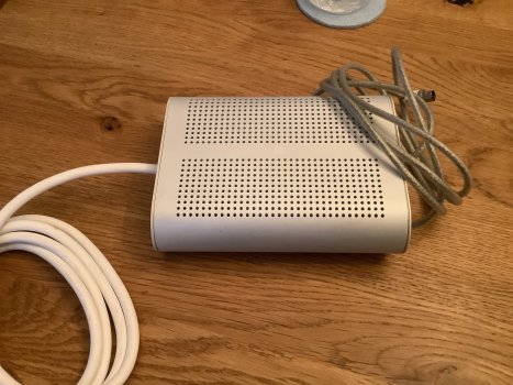
The Cube that I got had a dead PSU and I got a new one that just barely fits in the original case of the PSU, actually looking almost as "sexy" as before, with the difference that the AC cable is now mounted and not removable. It works good with a surprising low heat radiation.
So if anyone still has some dead original PSUs lying around, you can make them work again by swapping the internals for the cost of around 50 bucks and an extension cable. For completing the "sexy" look, you can attach a 3D-printed cable fixer to it so the mounted AC cable does not wobble around (view photos).
Note that the PSU replacement is 230V AC only, but it should be easy to find one for US 110V as well. Maximum sizes for a fit-in replacement are approximately 15.5x12x4.5cm or 6.1x4.7x1.8 inches if you want to find one on your own.

PSU replacement, 7A (230V only): https://www.ampul.eu/de/schaltnetzteile/4764-netzteil-28v-71a-200w
Cable fixer (stl format): https://drive.google.com/file/d/1q6lx5I1KuXfIMCA2S32jbx4UFC7nFziT/view
 

Attachments

  • IMG_0472.jpeg
    IMG_0472.jpeg
    663.8 KB · Views: 81
  • IMG_0473.jpeg
    IMG_0473.jpeg
    524.7 KB · Views: 110
Last edited:
Hi there, really nice thread, thanks for taking the time writing out your thoughts and result of analysis, as well as developing and publishing the upgraded VRM. I'm not too educated on electronics, but as I understood it, the main danger is of the FET overheating and blowing up and taking the motherboard/cpu/graphics card with it, and the remedy is to design a completely new board to accommodate modern and higher rated components.

However, I lack the skills in constructing the new VRM you put up, and I don't really feel like pushing my cube to its absolute limits, at least not until the VRM design is finalized/battle-tested... I have unfortunately learned the hard way about the weaknesses of the stock VRM, after a blown Q7 and toast motherboard (thankfully a second Cube I was playing around with)... but either way, I can't and don't want to push for the maximum, for now.

Instead, I'm wondering how well an upgrade of the original VRM would work if I went easy (?) on the upgrades: a single 7457 cpu upgrade, Radeon 9000 Pro, and SSD. If i steal the FETs from the dead board and stick them in the empty slots on the working board and put heatsinks on top, what kind of improvement in safety can I expect? If i understood correctly, there is still a risk of catastrophic failure before the overcurrent protection kicks in when using the stock board, due to other components? I'm not too sure calculating ... if it's threading too close to the limit then I'd rather not gamble.
 
Oh and I found another part that was damaged by the VRM destroyed by me: the SSD Adapter, it stinks just like the capacitor on the CPU board. Recently I bought a second Cube and wanted to install the SSD that I had in my first Cube, but the SSD wasn’t recognized. I found out that the IDE/SATA adapter was dead, and when I ordered a new one it worked just fine again.

I am also wondering if the parts that were destroyed when the VRM failed could maybe destroy back the VRM that I purchased from CubeUs when I install it.

And if let’s say, the stuff I soldered onto the MDD CPU board (CPU swap in my G4 Cube) is corrupt or I damaged something when soldering the coils to it, could it destroy the motherboard and the VRM or does my Cube just not power on and nothing happens?
 
If i steal the FETs from the dead board and stick them in the empty slots on the working board
I wouldn’t do that as there is a high risk that the other FETs have been damaged as well even if they pretend to be fine. If you learned the hard lesson like me (my VRM blowed the CPU and the motherboard as well as the SSD controller up) I would just throw away everything that has made contact with a destroyed VRM, as sad as it is…

upgrades: a single 7457 cpu upgrade, Radeon 9000 Pro, and SSD
Installing an SSD is always better than staying with the old HDD as SSDs use way less power than their older counterparts, especially in the first few seconds after booting up when the HDDs acclerate.

For the GPU, the string on the VRM that delivers power to the graphic card is more than stable enough for a Radeon 9000 Pro (but dies immediately with a 9800 Pro). I use a flashed GeForce 6200, imo just the way to go…

As for the CPU, I would recommend a beefed up VRM for the following models/clock speeds and up:

7400(200nm): only for duals that you overclock up to 550 or 600 MHz (7400s were never produced with higher speeds than 500 MHz)
7410(180nm): no new VRM needed as they were never produced as duals for Macs iirc
7450/7455(180nm): new VRM for duals or singles when ocing over 1.25GHz
7447/7457(130nm): only for duals or for singles with over 1.8Ghz
7448(you‘d be too lucky to get one in your hands today, 90nm): only for duals

For dual 7455/7447/7457s with very high clock rates I would even recommend a VRM bypass because the Motherboard itself is not made to redistribute so much power, but on most high-clocked dual upgrades these were included iirc.

In the end it‘s just a matter of how much safety you want to have. For the Dual 1.25 GHz 7455A I already ordered CubeUs‘s VRM as they would easily destroy the original VRM.
 
Important little update: I forgot to set the PSU adapter file accessible to everyone. Someone requested access to it and I now did it, the file should be downloadable now.
 
Hi all,
I hope I am right here. I am using a Artmix VRM in my G4 cube which is equipped with a Sonnet Encore 1.8 GHz G4 card. I am trying to use a 12V fan attached to the Artmix' 12V connector. However, the fan doesn't seem to spin up. All you can hear is some clicking noise. I am not using the fan that was delivered with the Artmix (same issue here) but have bought another 12V fan to rule out the fan itself as cause.

Interestingly Action Retro is reporting the same problem in one of his G4 videos.

So the question is: Is there a problem with the Artmix' 12 V connector? If so, can it be fixed?

Thank you!
CK
 
Not really right here, you could‘ve started a new thread on this (no problem btw). Nice to know you are also watching Action Retro!
From which component does the clicking noise come from; Fan or VRM?

First, test the voltage of the 12V connector. Is it even 12V?
If there are not 12V volts, the issue is clear, and if there are 12V, what I think is most likely because it happened not just to you, maybe the component transforming 28V to 12V is way to weak so that even a tiny bit of power pulled from the connector would cause the voltage to sink so drastically that the fan doesn‘t start to spin up.

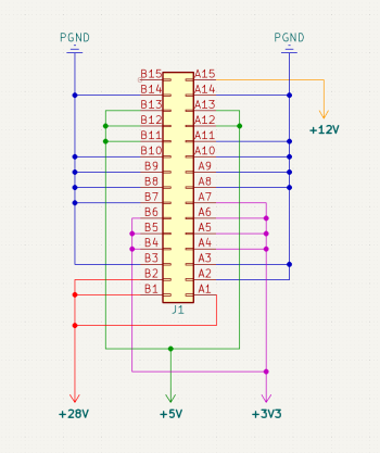
When you detect the second case, you can try to power the fan from the 12V pin and one of the GND pins from the backside of the the VRM slot of the motherboard where the pins stand out of it. The attached pinout shows the Motherboard from the top side with the IO ports (USB, LAN, …) facing downwards. Remove the connector from the fan cable, deisolate the tips of the fan cable a few millimeters and solder the two wires on to the pins.

If even that doesn’t work, you can try to replace the component responsible for the 12V plug. Unfortunately I don‘t know which component it is but you can ask @cuebus , maybe he knows what is.

Hope it helps!
 

Attachments

  • 1708348366994.png
    1708348366994.png
    59.2 KB · Views: 65
Last edited:
  • Like
Reactions: cktwo
Hi there, really nice thread, thanks for taking the time writing out your thoughts and result of analysis, as well as developing and publishing the upgraded VRM. I'm not too educated on electronics, but as I understood it, the main danger is of the FET overheating and blowing up and taking the motherboard/cpu/graphics card with it, and the remedy is to design a completely new board to accommodate modern and higher rated components.

However, I lack the skills in constructing the new VRM you put up, and I don't really feel like pushing my cube to its absolute limits, at least not until the VRM design is finalized/battle-tested... I have unfortunately learned the hard way about the weaknesses of the stock VRM, after a blown Q7 and toast motherboard (thankfully a second Cube I was playing around with)... but either way, I can't and don't want to push for the maximum, for now.

Instead, I'm wondering how well an upgrade of the original VRM would work if I went easy (?) on the upgrades: a single 7457 cpu upgrade, Radeon 9000 Pro, and SSD. If i steal the FETs from the dead board and stick them in the empty slots on the working board and put heatsinks on top, what kind of improvement in safety can I expect? If i understood correctly, there is still a risk of catastrophic failure before the overcurrent protection kicks in when using the stock board, due to other components? I'm not too sure calculating ... if it's threading too close to the limit then I'd rather not gamble.
Apologies for the delayed response. Lost track of this thread and got distracted with other projects. I think an upgraded stock VRM should be able to handle a 7457 and a 9000 pro. I wouldn't recommend using the original FETs though. The ones I shared in my DigiKey list have much more current capacity than the stock parts and also haven't been exposed to many years of stress. Some heatsinks on the new FETs are still recommended.

With an upgraded VRM, the overcurrent protection *should* kick in at 18.5A, before the new FETs blow. The only thing that will kill other components on your board is a high side FET failing short. However, I haven't actually tested an upgraded VRM on a load tester yet to ensure that OCP actually trips. I recently got a second cube, so I don't mind potentially blowing up one of the stock VRMs for science now. I'll try to update this thread once I get around to that.

In short, a stock VRM with 4 new FETs on each rail should be just fine for a single 7457 and 9000 pro.
 
I am also wondering if the parts that were destroyed when the VRM failed could maybe destroy back the VRM that I purchased from CubeUs when I install it.

And if let’s say, the stuff I soldered onto the MDD CPU board (CPU swap in my G4 Cube) is corrupt or I damaged something when soldering the coils to it, could it destroy the motherboard and the VRM or does my Cube just not power on and nothing happens?
It depends on a few things. If a component failed open, then there is no risk at all. If it failed short, then the output rail of a power supply powering it will be supplying that short circuit. If the power supply is well designed, it should have some kind of short circuit protection. Either a dedicated short circuit (usually faster tripping) or the basic overcurrent protection should trip when powering a device with a component that has failed short. If the protection trips, then nothing should happen. Maybe a very brief sign of life followed by no power; but no popping, fire, or smoke should be present if that is the case. However, we know that the stock Cube VRM has inadequate OCP, so it might blow one of those up by overheating it and causing one of its FETs to fail short. A short will cause a massive current to flow very quickly though, which may even be caught by the OCP of a stock Cube VRM and trip before the FET has a chance to melt. There is also a chance that the external PSU short/OC protection will kick in first, but that depends on how sensitive it is. In general, it should be relatively safe as long as you have confidence in the power supply.

If you want to be as careful as possible, you could test each component in isolation away from the core system that you are trying to avoid damaging. That can only go so far, but trying the video card in another machine that you care less about is one example. You could even put it in an old windows box. No need to see if it gets display output, just that the machine can power on with it installed and it doesn't cause any smoke.
 
And another possibly dead VRM!😭
A few minutes ago I powered on my Cube (with a stock VRM, stock CPU and GeForce 6200 which consumes less power than the stock ATI) just as normal and as I had it not in its case, I saw the red light on the Motherboard blinking a few times and then the MOSFET on Q9 blew up, produced a hell lot of smoke.
The last time I powered the Cube on was one week ago and it has been untouched since then, no parts replaced, so I have no idea what the problem could be.

I measured resistance on the Motherboard and luckily it is not damaged like the first MB was when I failed replacing the MOSFETs on my first VRM a few months ago.

I have still stored the original MOSFETs from the first VRM (which worked fine before unsoldering them) and replaced the dead one.

Measuring the resistance on all pads after replacing the dead MOSFET shows that nothing seems to be damaged and they didn’t failed D/S, G/S, or G/D. Now I am wondering what I could check next to make sure nothing has been damaged, and more importantly, WHAT THE HELL CAUSED THE MOSFET TO BLOW UP???
This happened to me some time ago and it blew up the MB as well. I think the stock VRM is very vulnerable. I originally thought it was my Cinema display that could have caused it, but that was not the case. I replaced it with the Artmix VRM and it works OK since then.
 
Hi all,
I hope I am right here. I am using a Artmix VRM in my G4 cube which is equipped with a Sonnet Encore 1.8 GHz G4 card. I am trying to use a 12V fan attached to the Artmix' 12V connector. However, the fan doesn't seem to spin up. All you can hear is some clicking noise. I am not using the fan that was delivered with the Artmix (same issue here) but have bought another 12V fan to rule out the fan itself as cause.

Interestingly Action Retro is reporting the same problem in one of his G4 videos.

So the question is: Is there a problem with the Artmix' 12 V connector? If so, can it be fixed?

Thank you!
CK
I just used the Molex connector with a splitter in stead of the Artmix connector. Works without a problem
 
I also measured resistance again and found out that on Q4, Q8 and Q10 pins 1-3 and 4-8 have a resistance of 104-108 Ohm, does that mean anything?

So can I try using Cuebus VRM instead of the stick one without a risk of it failing as well?
 
I put Cuebus VRM in my Cube but havent powered it on yet.
I only plugged the 28v power into it and every time I plug the power cable in, I can hear a click. If I remember correctly this click sound hasnt appeared yet but I am not sure about that. Does that man anything?
 
Register on MacRumors! This sidebar will go away, and you'll see fewer ads.