Become a MacRumors Supporter for $50/year with no ads, ability to filter front page stories, and private forums.

KeesMacPro

macrumors 65816
Nov 7, 2019
1,453
596
@p11hlf :
I'v planned to test the NF-A12X25FLX this Friday, because of work I have to do on the same computer.
as soon as I can I'll let you know.


I think this is almost certainly because at the target default SMC RPM it will be outputting a voltage below that fans starting voltage.
Only way to be sure would be multimeter probes on the pins and test the minimum starting voltage of the fan and it's corresponding RPM. Will await further info on the A12x25 FLX as it may be more voltage tolerant than the industrial models.

@amedias :
I'm afraid this could be the case with the 12x25FLX too...
Based on the test voltage (V=5,0v min.) and the fact that rpm max is 2000rpm....
So Vmin is 40% , but it should run at 30% of the speed...


Compared to the NF-A9FLX I installed: V=4,5v rpm max=1600, so its running at 50% of the speed (800rpm) with min. voltage about 35% of 12V.

Anyway I'll measure the voltage once I got it installed with SMC running ...
 
Last edited:

KeesMacPro

macrumors 65816
Nov 7, 2019
1,453
596
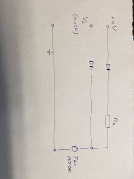
To fix this in hardware you need to make sure that there is a minimum voltage applied to the VCC pin on the fan regardless of output on Control pin 4 of the board. You can do this by taking VCC pin2 from the board and connecting it to the fan *in addition to the Control pin 4*. You will need to use an inline resistor to drop the 12V VCC input to whatever the minimum Voltage your fan needs to run. You should probably also use a diode in line *before the connection from VCC pin on the board* to prevent any input back to the board. If you do this then the fan will always have an applied voltage so cannot stop, the SMC will be happy and Control voltage will be at a minimum until thermal conditions dictate it need to be increased, this will then increase the Voltage to the fan and it will run faster just as it should.


.... if needed I might go for this option.
One thing I would add: another diode to be absolutely save (see attachment).
Just in case..

Have you tested this option?
 

Attachments

  • IMG_2629.JPG
    IMG_2629.JPG
    212.9 KB · Views: 251

amedias

macrumors 6502
Original poster
Feb 9, 2008
263
289
Devon, UK
.... if needed I might go for this option.
One thing I would add: another diode to be absolutely save (see attachment).
Just in case..

Have you tested this option?

2nd Diode was in my head just not written in the post so thank you for pointing that out!

I've not tested it yet as I've not yet had a need to, all the fans I want to use behave well enough in my machines but it is something I intend to do at some point just to make sure it does work as I expect.

If you have the free time and want to give it a go please report back.
 
  • Like
Reactions: KeesMacPro

tomsmods

macrumors newbie
Oct 24, 2018
25
17
California
.... if needed I might go for this option.
One thing I would add: another diode to be absolutely save (see attachment).
Just in case..

When I would reduce fan noise by dropping the fan input voltage I typically used zener diodes or regular diodes in series instead of resistors. That way I did to not have to worry as much about calculating the resistance values and/or heat dissipation needed to achieve the desired voltage drop.

The diode on the variable voltage line would protect from the 12V back-feed but would also drop the voltage on this line slightly. It would possibly not allow the fan to operate at maximum...which might not be a bad thing if your goal is quieter operation. The SMC's voltage targets wouldn't really apply anyway since the fan would be different.


My other thought would be using a Microcontroller to convert the variable voltage to a usable PWM signal to use PWM fans as-is with the +12V signal.

I did a quick search for this and found: PWM to voltage controlled fan hub conversion.

This project appears to have been for multiple PWM fans connected to a PWM hub to be controlled by a single variable voltage source motherboard header. I think something like this could be applicable, probably by replicating the Microcontroller setup for each desired control area. It may also allow for compatibility with more fans.
At the very least, the hardest part -- the code used -- is shown!
 

amedias

macrumors 6502
Original poster
Feb 9, 2008
263
289
Devon, UK
Thanks Tom, more things to try ;-)

As i noted in the original post though, one of the primary goals of this was to avoid using too much extra 'stuff' to get a workable solution. I've got no objection to PWM converters* and/or additional controllers, but if we can get something that works without then that'd be my preference. Just from an ease of use and packaging POV.

* I know of at least one working setup in a Mac Pro like this, but the guy went through about a dozen iterations and PCB prototypes, and as yet hasn't agreed to offer turn-key solutions for sale for plug 'n play replacement.
 

amedias

macrumors 6502
Original poster
Feb 9, 2008
263
289
Devon, UK
Updates from multimeter tests.

With the OEM Apple/Delta fans output on VControl pin @smc minimum RPM is ~1-2V

With aftermarket fans *at the same RPM* output on VControl is whatever Voltage is needed to hit the RPM.
I tested half a dozen fans and the Voltage ranged form ~5V to 12V depending on what the RPM specs of the fan were.

This confirms that the SMC uses target RPMs and adjusts voltage to reach the desired RPM.

What this means is that if you want to just swap pins and plug a new fan in then it is an absolute requirement that the fan you choose be able to spin stable at the SMC minimum RPM for the header you're attaching it to. The SMC will increase voltage as necessary to hit that RPM but it must be able to spin at that speed.

This is likely why some of the higher RPM (and 4-pin) fans are stalling, if they won't run at the minimum RPM then there's not much the SMC can do, it'll increase voltage till they do spin, but then when it tries to drop back to the target minimum RPM the fan stalls.

So you need to choose fans that have a compatible minimum RPM. That can either be a low RPM fan with a lower max RPM than the Apple fans if that will fulfil your cooling needs, or a fan with a wide RPM operating range, but not* a high RPM fan with a narrow operating range.

* @KeesMacPro and I are still investigating the diode/resistor option for retro-fitting this type of fan, but it will require a small adaptor cable, so potentially 'more' plug and play as may be no need to swap pins on the fan (can be done in the adaptor), but adaptors will need to be specific to the model of fan you want to fit.

This is what I found out earlier today (but didn't post until @KeesMacPro had confirmed in his test too as I tested without diodes and din't want to encourage such madness in the thread!)

little update, finally got an new multimeter today so ran a quick test with one fan that I have that I know runs at low voltage and low RPM successfully

I did this without the diodes so was taking a little bit of a risk!

tests done on the PSU fan header with a Nanoxia Deep Silence 400-1400RPM 3-pin fan:

Test 1 - plugged in to header with PC pinout
Runs at 1400RPM straight off VCC @12V as expect

Test 2 - plugged in to header with pin swap
Running at 400RPM VControl output was @5.1V (manual SMC control)
Running at 500RPM VControl output was @6.3V (auto SMC control)
Running at 1200RPM VControl output was @10.8V (manual SMC control)
Running at 1400RPM VControl output was @12.3V (manual SMC control)

Test 3 - plugged into the header but with a step down adapter running from VCC dropping VCC to 5V
Running at 400RPM VControl output was @0.2V (manual SMC control)
Running at 500RPM VControl output was @1.2V (auto SMC control)
Running at 1200RPM VControl output was @5.1V (manual SMC control)
Running at 1400RPM VControl output was @7.3V (manual SMC control)

So looks like it is working!

I tried one final test to see...tried to force 2800RPM (SMC max), but it carried on running at 1400RPM but VControl output was @12V so looks like the SMC was willing to up the voltage but the internal protection on the fan kicked in preventing it running any faster.

All looks promising, I just need to get hold of some >200RPM fans now to properly test but it looks like it's possible.

Would love to hear how you get on to see if you get similar results.
 
Last edited:
  • Like
Reactions: Champagne_5S

KeesMacPro

macrumors 65816
Nov 7, 2019
1,453
596
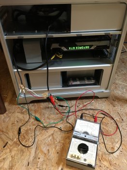
I just finished testing the noctua NF-A12x25FLX as a possible PSU fan.

I did different setups:
#1- Testing min voltage =5,0v (which corresponds with 900RPM I found out later) with a power supply stable <5000mA.

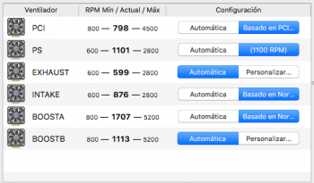
#2- Testing connected to the header :
2000rpm @12,0v
1600rpm @8,6v
1400rpm @7,4v
1200rpm @6,3v
1100rpm @5,7v
With rpm set lower (MFC) , issues start , and its not stable ,especially after sleep it takes very long to spin up or even never starts.
It seems like SMC voltage fluctuates to much for this fan under 5,5v.


#3-connected to the 12v pin , with a serial resistor(calculated at 5,0v), it runs unstable and MFC shows alternating 365 and 550rpm.

#4-the same as #3 but adding a diode, something strange occurs: MFC shows 250rpm stable, the fan spins but I think it made some funny noise.

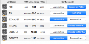
#5-fan powered by Vc and 12v, connected as we discussed previously.
Fan runs stable at lower rpm:
1000rpm @5,2v
900rpm @5,0v

No wake/sleep issues, relatively fast respons after sleep.
This fan could be nicely controlled by TGPro for example with rpm 900-2000...

So #5 could be a great option if you'd like to run (whatever) fan as slow as possible!
Its 2 diodes and 1 resistor , so one could easily solder them into the cable and cover them with heat shrink tube...

EDIT: @p11hlf : This model shows the same characteristics as yours: runs fine 1100-2000RPM , or if you'd like to solder a bit, as described here , it goes down to 900rpm...
 

Attachments

  • IMG_2632.JPG
    IMG_2632.JPG
    492.6 KB · Views: 274
  • RPM min. Vc.png
    RPM min. Vc.png
    54.6 KB · Views: 243
  • RPM min. Vc + V12v..png
    RPM min. Vc + V12v..png
    54.6 KB · Views: 190
  • 12v serial resistor+ diode.png
    12v serial resistor+ diode.png
    54.6 KB · Views: 249
Last edited:
  • Like
Reactions: amedias

amedias

macrumors 6502
Original poster
Feb 9, 2008
263
289
Devon, UK
Excellent update thanks @KeesMacPro, this is pretty much exactly what we expected would happen and tallies nicely with my own testing. Great to get confirmation from another tinkerer!

*high five*

so now we have two verified options:

1. straight forward pin swap for lower RPM fans if they will suit your cooling needs

2. Simple inline cable modification OR an adapter cable to use higher RPM fans if you don’t want to mod the fan cable at all.

since *most* 12v 3-pin fans on the market have a minimum starting voltage of 4.5-5V a generic 5V step down adapter will probably suffice for all but the most unusual fans.

It should be possible to build adapter cables very cheaply and only basic soldering required so an easy home job for <£5 for most I should think, resistors and diodes cost pennies, only cost really would be the connectors for the adapter cable, but they can also be picked up in bulk for not much.
 
Last edited:
  • Like
Reactions: KeesMacPro

KeesMacPro

macrumors 65816
Nov 7, 2019
1,453
596
Excellent update thanks @KeesMacPro, this is pretty much exactly what we expected would happen and tallies nicely with my own testing. Great to get confirmation from another tinkerer!

*high five*

so now we have two verified options:

1. straight forward pin swap for lower RPM fans if they will suit your cooling needs

2. Simple inline cable
modification OR an adapter cable to use higher RPM fans if you don’t want to mod the fan cable at all.

since *most* 12v 3-pin fans on the market have a minimum starting voltage of 4.5-5V a generic 5V step down adapter will probably suffice for all but the most unusual fans.

It should be possible to build adapter cables very cheaply and only basic soldering required so an easy home job for <£5 for most I should think

My pleasure!

The adapter cable was a very good idea!
Indeed it's easy to solder, costs are like not worth mentioning , the only thing is to calculate the resistor accurately , based on voltage and current at Vmin...

EDIT:btw this fan is way more silent @900rpm than the OEM @600rpm!
Even at 2000rpm its very silent.
 
Last edited:

KeesMacPro

macrumors 65816
Nov 7, 2019
1,453
596
When I would reduce fan noise by dropping the fan input voltage I typically used zener diodes or regular diodes in series instead of resistors. That way I did to not have to worry as much about calculating the resistance values and/or heat dissipation needed to achieve the desired voltage drop.

The diode on the variable voltage line would protect from the 12V back-feed but would also drop the voltage on this line slightly. It would possibly not allow the fan to operate at maximum...which might not be a bad thing if your goal is quieter operation. The SMC's voltage targets wouldn't really apply anyway since the fan would be different.


My other thought would be using a Microcontroller to convert the variable voltage to a usable PWM signal to use PWM fans as-is with the +12V signal.

I did a quick search for this and found: PWM to voltage controlled fan hub conversion.

This project appears to have been for multiple PWM fans connected to a PWM hub to be controlled by a single variable voltage source motherboard header. I think something like this could be applicable, probably by replicating the Microcontroller setup for each desired control area. It may also allow for compatibility with more fans.
At the very least, the hardest part -- the code used -- is shown!

The diodes are not meant for voltage drop, but to avoid "funny" currents running between Vc and V12v. Thats why I integrated 2 of them (for both voltage lines ).
About the voltage drop because of the diode: I doubt it will have a huge effect...at least I didn't measure any voltage drop in this case...

Quote:That way I did to not have to worry as much about calculating the resistance values and/or heat dissipation

I don't think a resistor in any electrical circuit should be dissipating heat...
It takes less than 1 minute to calculate the min power rating for a given resistor...
 
Last edited:

ukhanspam

macrumors newbie
May 14, 2020
4
0
I've been reading around this subject for a while as a pet peeve of mine is noisy computers.
My normal workstations are entirely passively cooled and silence is bliss, but I do still use my cMPs when I need machines with a bit more power or more cores for testing virtual environments and the noise of my 5,1s has always annoyed me.

I don't mind them making a little noise when they're really working, but in low utilisation and idle states I still get annoyed by them even with all fans on minimum.

So I started reading all the various threads on replacing stock fans with quieter ones (Noctua or Gelid being my preference) and there's seemingly a few people that have done this, although the Apple-specific PWM implementation* always seems to be the gotcha. I'm posting this as a bit of a compendium of info from other threads and my own testing for those that might be interested.

* Apple Mac Pros don't use PC style PWM to control their fans, instead of a square wave switched input on pin 4 at different duty cycles (PC style) they use an analogue variable voltage.

First a history lesson on fan pinouts

Old school fans, also known as 2-pin fans
1 - GND
2 - VCC** (normally 12V)

These fans run at constant RPM based on the input voltage (12V) and provide no tacho reading so the system cannot tell what the RPM is. A lot of old PCs and old PowerMacs used these fans, cooling is basically configured for 'worst case scenario' with all fans running all the time, when the system is idle then it's cool and noisy, when it's loaded its hot and noisy (and hopefully doesn't ever reach 'overheat'.

** note on VCC...
Input voltages other than 12V can be used and the fan will run slower or faster accordingly. If the voltage is too lo the fan may stop, if too high it may burn out.

PC fans with tacho, also known as 3-pin fans
1 - GND
2 - VCC (normally 12V)
3 - Sense/Tacho

These fans run at constant RPM based on the input voltage (12V), they also provide a sense/tacho reading on an additional pin which the system can read to report on fan speed, fan failure and with some systems they will be able to vary voltage on the VCC pin on the motherboard to vary fan speed. This is not PWM, but does allow motherboards to vary fan speed in response to thermal conditions, and the tacho allows them to receive feedback on the fan status.

PC PWM fans, also known as 4-pin fans
1 - GND
2 - VCC (normally 12V)
3 - Sense/Tacho
4 - PWM control signal

These fans run at variable RPM based a PWM signal on pin 4, like 3-pin fans they provide a sense/tacho reading on pin3 which the system can read to report on fan speed and fan failure it also acts as feedback to adjust the PWN signal. With these fans VCC is constant and the RPM of the fan is controlled by an internal motor driver circuit which responds to the PWM signal, a switched 25kHz square wave where the duty cycle of the wave dictates fan speed.
A point here which will be relevant later, is that just like 2 and 3 pin fans, the fan draws the bulk of it's current to run the motor from VCC on pin 2.

Apple Mac Pro fans, also known as "Damn you Apple and your proprietary nonsense!" fans
1 - GND
2 - VCC (12V)
3 - Sense/Tacho
4 - Apple RPM control,

These fans run at variable RPM based on the control signal on pin 4, like 3-pin fans they provide a sense/tacho reading on pin3 which the system can read to report on fan speed and fan failure it also acts as feedback to adjust the control signal. Unlike PWM fans the control signal which is used to drive the motor is an analogue voltage variable from 0V to ?V (I need to get a new multimeter to confirm the max but I suspect it might be 12V based on reports from others). the 12V on VCC is constant and used to drive the fan control circuitry and the motor at min speed.
Back to that point above, I need to test this myself (when the new multimeter turns up) but it appears from reading other sources that the fan draws the bulk of it's current to run the motor from Control on pin 4, more on this later!

So you can see the issue plainly, if you plug in a PC PWM fan to a Mac Pro header the PWM signal will not work, and the fan will run at full speed due to 12V on VCC pin. It will however report RPM back to the SMC so at least you can see the fan speed in your software of choice.

Most people I've read about seem to adopt one of four approaches:

1. Use PC fans plugged into the Mac Pro headers and let them run at full speed
2. Use PC fans plugged into the Mac Pro headers and use inline fixed resistors to run < full speed
3. Use PC fans plugged into the Mac Pro headers and use inline variable resistors to run at manual controlled speed
4. Use PC fans and conversion/adaptor boards to convert Apple control signal to PC PWM signal

Options 1 & 2 are simple and if you choose your fans or resistors carefully can result in lower noise, but there's no variable RPM so no way to adapt to changing thermals so you have to plan for either never running the machine at full load for extended periods, or making sure your cooling is sufficient for 'worst case scenario' and just put up with whatever the noise level is.

Option 3 is a little better as you have manual control over the fans, level of annoyance will be dictated by where the controls are physically located and how often you need to tune RPM to workload. Which fine if you're sat next to the box all day ;-)

Option 4 is a great option as you can use unmodified fans and have full automatic control of the fans. It is however very hard to achieve, many have looked into this but I've not (yet) seen a single case of someone confirming they've got it working 100%, and certainly no easy off-the-shelf solution I've seen. It also leaves you with the problem of where to stash the converter board(s).

Now, I'll refer you back to the pinouts above, there is a 5th option, and it's a workable solution if you choose your fan models with care.

Option 5!

Use 3-pin PC fans, plugged into the Mac Pro headers but with a few pins swapped.

If you take a normal 3-pin PC fan, pop the pins out of the connector and replace them into the 4 pin connector from a Mac Pro fan but arrange the wires from the fan like this:

Mac Pro outputPinFan input
GND1GND
VCC (12V)2* empty *
Sense/Tacho3Sense/Tacho
Control voltage4VCC


What you end up with is a 3-pin PC fan, being driven off the analogue variable voltage from the Mac Pro Control pin 4.
This is the exact same type of control you get on motherboards that can vary the speed of 3-pin fans, and is the same as using step down resistors (fixed or adjustable) but it has the added benefit of still letting the SMC do automatic control.

So this DOES give automatic fan control that the SMC can manage, and as long as a few conditions are met works 100%. If those conditions are not met then you can still get ~80-90% of the way there and fan control software can get you the other 10%, see below for details.

So there must be a gotcha with this too right? Well yes... but easy to deal with.

Issue 1
The Mac Pro control voltage can be very low, even 0V, below a certain voltage (about 3V IMEbut some are lower) most fans can't operate so this will cause the fan to stop, the SMC obviously doesn't like this so will pulse the control voltage to get the fan to restart so you'll just hear your fans momentarily stop and restart all the time at idle.

You can deal with this with a hardware mod or in software. In software just set the minimum speed of the fans to a high enough level that the voltage on pin 4 is sufficient to drive the fan. You can either do this by trial and error watching the RPM pulsing, or get your multimeter out and work it out, but that's it. Set minimum speed in Macs Fan control, or iStat or whatever you use and it will still vary UP from there as necessary. If you choose your model of fan wisely (medium/high RPM at 12V) you can get a minimum speed close or equal to the minimum of the original Apple fans and with your adjusted fan curves it'll be cool and quieter.

To fix this in hardware you need to make sure that there is a minimum voltage applied to the VCC pin on the fan regardless of output on Control pin 4 of the board. You can do this by taking VCC pin2 from the board and connecting it to the fan *in addition to the Control pin 4*. You will need to use an inline resistor to drop the 12V VCC input to whatever the minimum Voltage your fan needs to run. You should probably also use a diode in line *before the connection from VCC pin on the board* to prevent any input back to the board. If you do this then the fan will always have an applied voltage so cannot stop, the SMC will be happy and Control voltage will be at a minimum until thermal conditions dictate it need to be increased, this will then increase the Voltage to the fan and it will run faster just as it should.

EDIT - No longer worth worrying about as long as you use decent fans. I tested about a dozen today off the Mac Pro board header running with pin swap described above. It seems the SMC has target RPMs set for minimum value, rather than target voltages. Which means if you plug any fan in when it will try to run it at the default RPM (examples: 500RPM on the exhaust, 600RPM on the intake) and will just increase the voltage until it sees the RPM it wants.

What this means is that as long as you choose fans that can run at the minimum RPMs without stalling then you won't get the pulsing. What this also means is that once it starts ramping up once the voltage gets to 12V and stops increasin the SMC can have no further effect. So it pays to use fans that will run at high RPM @12V, yet will still run at the minimum RPM the SMC targets.
See further update post down the page for more info and examples.

ADDITIONAL EDIT - Resistors and diodes now confirmed as a workable solution by @KeesMacPro and myself today, see page 4!!

Issue 2, possibly?
Until I get my new multimeter I can't confirm what the max voltage seen on Control pin 4 is, there is a very small chance it's high enough to damage some fans, however all the fans I've tested have run fine at max RPM with no issue so I suspect it is indeed 12V as I've read elsewhere.


EDIT - Not an issue! I tested every PC fan I could lay my hands on in the house (about 20) and fed them various voltages, confirmed max RPM at 12V (as expected) and RPM did NOT increase beyond that even when fed with 20V so can be 99.99% sure that the fans have over-voltage protection built in and limit 12V to the motor. Sure you might be able to fry it by feeding >20V but that's not gonna happen.

ADDITIONAL EDIT - Max output on VControl pin is 12.3V, so NO risk of damaging fans.

Issue 3, maybe?
Until I get my new multimeter I can't confirm whether the standard Mac Pro fans draw most of their current off VCC pin 2 or Control pin 4. If it's from pin 4 then this is not an issue at all. If it's pin 2 then there is a very small chance that at high RPM pin 4 may not be able to provide sufficient current. I do not think this is the case is in my own testing (with several different fans) I was able to successfully run them up to max RPM without issue so I suspect what I've read is true.


EDIT - Not concerned about this any more but will still check when multimeter arrives, see post furhter down, but after running several fans off the Mac Pro headers via the V Control pin no issues seen.

So in summary, with a simple pin swap you can use PC 3-pin fans and get automatic fan control, you may need to set a minimum speed in software to keep them ticking over at idle, but with care fan choice this isn’t necessary. This requires NO soldering, NO converter boards and is totally reversible.

I'll be back to update and amend the outstanding questions once I've got my hand on a multimeter again!

Heartfelt gratitude for wrestling with this cumbersome issue. I found a converter on Ebay that takes input voltage and produce PWM signal. It's listed under the phrase "New Current to Voltage Converter Module Signal Transmitter 4-20mA to 0-10V:"


Could something like this be used to bridge "Pin 4 - Apple RPM control" to produce PWM signal for the 4 Pin PWM fans being sold by noctua? I realize it maxes out at 10 Volts, but there are users tested in excess of 10 Volts - their warning is not to push it 15 Volts.
 

tomsmods

macrumors newbie
Oct 24, 2018
25
17
California
I don't think a resistor in any electrical circuit should be dissipating heat...
It takes less than 1 minute to calculate the min power rating for a given resistor...

Amedias and KeesMacPro, Thanks for all your hard work!


Yes, I understood your were using the diodes as protection.

Reducing a 12V line to 5V, a resistor would dissipate dissipates ~0.5W so you need a larger 1W resistor.
Reducing a 12V line to 5V with a zener usually dissipates ~0.05W so you can use a smaller component.
Of course if its near the fan itself it helps with cooling but my uses were in tiny cases, away from airflow.


This got my curiosity and I did some searching on forums on others doing the opposite and saw some people did deep dives into the operation of the original fans to drive them with PC motherboards.

I think part of the big reason for "proprietary" is it the fan controller design was done long before (4-pin fans have been in Macs for a long time) and they keep reusing the design even though the rest of the industry slowly changed to something else. It's already done, tested, and configured in their software.

It would be fun to figure out if the SMC signal actually is some type of PWM that the drive circuit converts to a variable voltage...
 

amedias

macrumors 6502
Original poster
Feb 9, 2008
263
289
Devon, UK
There are PWM->Voltage and Voltage->PWM converters available on eBay and elsewhere, I already have a selection on their way to me from China but still a week or two away I think with current shipping.

I know others have tried these and met with some success, I think there’s another thread down the page about it... but I know some have also not got them working so not sure if it’s that they bought the wrong board, or miseries them or what.

I’ll be testing them when they arrive, I’m sure they’ll work fine but one thing I was trying to avoid was converter boards.

Even when they work 100% correctly you still either need one per fan, or one bigger master controller. It’s extra cost ~£3-5 per board/fan, extra wiring, extra hardware to have to hide in the case somewhere and an extra bit of hardware that might fail or that the user might miswire.

I’ll still post my results once they arrive though as it’s another option for people to consider.
 

p11hlf

macrumors member
Jul 27, 2018
69
44
Southampton UK
nice work guys! ill wait for a fan list to build before going any further. As I'm working on another Mac Pro project right now..... if the noise gets to me I might consider a Nanoxia Deep Silence 400-1400RPM 3-pin fan

thanks!
 
  • Like
Reactions: KeesMacPro

Tomblin

macrumors newbie
May 3, 2020
4
2
Curious what effect we'd see from re-pinning Noctuas provided in line resistance? They call their their LNA and ULNA "low noise adapter" and "ultra low noise" would this be a possibility for people who don't like soldering

I've been running a NF-A12x25FLX with the re-pin as an intake fan and it seems pretty happy we 1,000 RPM but anything lower and indeed the stall and surge begins.

Has anyone noticed an increase in the load on the PSU if you ask SMC to provide higher RPM than a fan is capable of? I asked a 4 pin noctua in the PCI to exceed it's factory 1,600 (which it did not) and I noticed the PSU fan ramp up, assuming to accommodate the additional demand?
 

KeesMacPro

macrumors 65816
Nov 7, 2019
1,453
596
Curious what effect we'd see from re-pinning Noctuas provided in line resistance? They call their their LNA and ULNA "low noise adapter" and "ultra low noise" would this be a possibility for people who don't like soldering

I've been running a NF-A12x25FLX with the re-pin as an intake fan and it seems pretty happy we 1,000 RPM but anything lower and indeed the stall and surge begins.

Has anyone noticed an increase in the load on the PSU if you ask SMC to provide higher RPM than a fan is capable of? I asked a 4 pin noctua in the PCI to exceed it's factory 1,600 (which it did not) and I noticed the PSU fan ramp up, assuming to accommodate the additional demand?

The effect of the LNA /ULNA cables is that it only lowers the max RPM of the fan.
It doesn't lower the min. RPM of the fan.
This has been tested by @amedias and other persons including myself.

About the effects on the SMC : Look for the posts by amedias, this has been tested too and an explanation/description of the results by amedias can be found in this thread.
 

tar1na

macrumors newbie
May 17, 2020
4
12
I've done this mod on a single CPU tray mid 2009 Mac Pro 5,1, thank you very much for the tips in the forums.

I used:

1 x Noctua 92 x 92 x 25mm NF-B9 redux-1600
3 x Noctua 120 x 120 x 25mm NF-S12B redux-1200
1 x Noctua 80 x 80 x 25mm NF-R8 redux-1800

Much more silent now under a heavy load compared to stock fans and temps are perfect. Very enjoyable. The only audible thing during idle is the Radeon VII in the box, so I'm drawing considerable power already.

Some things I learned:

- Intake and exhaust fans are super easy to change once you learn how to take the tray out and disconnect speaker & two fan cables
- CPU 6-pin connector could have a pinout mapping here to help others out: I discovered GND starts from the third pin from the left, after the two thermal monitor cables. Other pins from left to right are the same in order as for EX/IN/PSU but in reverse
- New thermal paste makes wonders to CPU temps
- GND is 1st pin for EX/IN/PSU from the right
- PCI is easy to install if you use screws to put the fan in and cut out the rubber legs
- For PSU, you do not have to remove motherboard to change it. Just disconnect the old fan from the motherboard, remove the cable under the motherboard and install the new one through the same route as the motherboard power connector goes (through the DVD compartment, behind the plate)
- PSU rubber legs are easily reused if you put them back in reverse (first in the fan, then in the box)

Probably some adapter cables in the future would make this whole process extremely fast to complete.
 

KeesMacPro

macrumors 65816
Nov 7, 2019
1,453
596
Much more silent now under a heavy load compared to stock fans and temps are perfect.

I'm very interested in the fan speed setup.
Could you maybe post a screenshot of MFC, iStats or whatever tool you're using to adjust the T vs. fan speeds?
Thx in advance.
 

romaric17

macrumors newbie
Jun 30, 2019
10
2
Bordeaux, France
Hey everybody.

In a dual CPU 2009 MP 4,1 flashed to 5,1 I have replaced CPU BOOST fans with Noctua NF-A6x25-FLX (3 pin). SMC doesn't like them, it has difficulties to drive their speed.


TGPRO reports that these fans may not be working properly: BOOSTA, BOOSTB. Is it told by the SMC itself?

> At low target rpm, NF-A6x25-FLX won't spin.
It seems that the SMC increases the voltage a bit but in the end it fails. MFC or TGPro show 300/400/800/900/0rpm. In the end the SMC seems to resign and leaves the fans off.

> If I set higher RPM (1200rpm+) in MFC or TGPRO:
most of the times, immediately or after a certain amount of time, the fans will spin at the required speed. The maximum seems to be 3600rpm for this model at 12V.


NF-A6x25-FLX minimum voltage
I have asked Noctua trough their website contact form what the minimum voltage required is for NF-A6x25-FLX. They answered pretty fast: 4.4V.

Diodes + resistor calculation to feed the fan its minimum required voltage
I guess I should use the diodes and resistor tip to feed NF-A6x25-FLX the minimum 4.4V using the VC 12V line. This way they will always spin at their minimum speed (1200rpm or so, haven't tested accurately).
However I am unable calculate the resistor needed to drop 12V to 4.4V. For this I need to know the intensity of the 12V line for CPU BOOSTA/BOOSTB, isn't it?
 

amedias

macrumors 6502
Original poster
Feb 9, 2008
263
289
Devon, UK
@tar1na , that's great, thanks for the update! The single CPU models are a lot easier to do and there's a better choice of 80mm fans that will work than there are 60mm for dualies.

Have you done full load tests to make sure the lower RPM fans are sufficient for your needs? They almost certainly are unless you live in the tropics as the default cooling capability for the cMP is massively over specified for 'normal' use.

TGPRO reports that these fans may not be working properly: BOOSTA, BOOSTB. Is it told by the SMC itself?

TG Pro will report any fan that does not conform to the original specs as potentially failed, and can even be tricked into reporting good fans as failed if you manually update SMC limits before starting TG Pro.

Noctua NF-A6x25-FLX is a 3000RPM fan*, there's no min RPM listed on the website but it is *highly unlikely* this fan will run at the SMC default minimum speed (600RPM)

I've mentioned it numerous times over the course of the thread but any fan you intend to use with (just) the pin swap method must be able to run stable at the SMC minimum RPM, or you will get issues with pulsing or fans stopping. With such a high RPM fan it's likely the minimum stable speed is dictated by it's minimum starting voltage and will most likely be in the ~1100RPM @4.5V area. The PWM version of that fan will run at 550RPM so the motor itself is clearly capable, but that's a different method of control and a PWM fan still gets the full 12V.

Most 12V fans have a minimum starting voltage of 4.5-5V, but some will start at lower voltage, and some will need the full 5V to start but can then run stable at lower voltage.

The minimum stable RPM at min voltage is what you need to pay attention to. If in doubt you should test the fan *before* fitting it to find its min starting voltage and minimum stable RPM.


Diodes + resistor calculation to feed the fan its minimum required voltage
I guess I should use the diodes and resistor tip to feed NF-A6x25-FLX the minimum 4.4V using the VC 12V line. This way they will always spin at their minimum speed (1200rpm or so, haven't tested accurately).

Yup, if you want to use those fans that's likely your only option. We are still testing this setup to verify if it works reliably. We've managed to get it working with a couple of fans, but needs further data to draw any conclusions, so since you have those fans to hand if you want to try it and test and report back to us that'd be great!

* Whether you need a 3000RPM fan will be down to your specific requirements. In my environment and my use case I can run a dual CPU (2x130W TDP) machine at full load 24x7 with BOOST fans < 1700RPM without any issues whatsoever, and under normal use I rarely see anything above 1200RPM. For 95W TDP CPUs the requirement is even less (1500/1100).
 
Last edited:
  • Like
Reactions: K15

KeesMacPro

macrumors 65816
Nov 7, 2019
1,453
596
I have replaced CPU BOOST fans with Noctua NF-A6x25-FLX


To calculate the voltage drop over the resistor, you will have to measure the min Voltage it runs smooth and measure the current at this voltage.
 
Last edited:

Flamenco Dude

macrumors newbie
May 16, 2020
3
0
I've done this mod on a single CPU tray mid 2009 Mac Pro 5,1, thank you very much for the tips in the forums.

I used:

1 x Noctua 92 x 92 x 25mm NF-B9 redux-1600
3 x Noctua 120 x 120 x 25mm NF-S12B redux-1200
1 x Noctua 80 x 80 x 25mm NF-R8 redux-1800

Are those PWMs?

Thanks
 

romaric17

macrumors newbie
Jun 30, 2019
10
2
Bordeaux, France
To calculate the voltage drop over the resistor, you will have to measure the min Voltage it runs smooth and measure the current at this voltage.

I'd like to make this test correctly.
I set the lowest reachable and stable RPM for NF-A6x25-FLX with MFC or TG PRO (around 1100/1200). It should represent a measured voltage of 4.4V or so. Then, I measure the current intensity at this voltage.
Am I right?
 
Register on MacRumors! This sidebar will go away, and you'll see fewer ads.