Become a MacRumors Supporter for $50/year with no ads, ability to filter front page stories, and private forums.
@185…….

You make an important point which potential upgraders should try and understand…….

In the original arrangement - i.e. with de-lidded processors the heatsink screws pull fully home (mechanically) onto the four stand-off studs and the copper plate sits firmly on the wider 'lands' on those studs and is pulled down tight onto them.

As such, a prescribed torque setting is appropriate because the mechanical arrangement is carefully designed to seat (but not overly squash) the processor(s) in their sockets.

If replacing with de-lidded cpus there is no difference, the same hardware works.

If replacing with lidded versions you cannot rely on the above unless you pack the standoff studs with carefully measured, non-compressible spacers that are equivalent to the difference in height between the two types of CPU ( 2.24mm I believe). This way the heatsinks can be fully but gently tightened because, while not identical, the error in 'gapping' is likely to be reduced to about 0.05mm - which I suspect is OK for our purposes.

Counting turns of the screws may well work but its a bit too hit n miss for my liking AND it relies on squashing the CPU itself to get any firmness at all on the heatsink screws……… which strikes me as a bad thing.

??

TAMM

Very well written - thank you for that!

I know of three methods and I think you allude to them here - install de-lidded processors, install lidded processors and use carefully sized washers to allow fully tightening the heat sink bolts, and the least reliable method of all - install lidded processors and count turns without using any washers.

That last method really complicates the torque question because the resistance is now based on any remaining thread lock material and the upward force of the the processor socket pins. The use of a torque wrench in this situation is meaningless because there is no documented specification for the necessary torque - the Apple documented torque specification only applies when the heat sink makes contact with the threaded stand-off studs, and that specification is there to protect the threads.
 
I have done this upgrade 3 times now.

The first time I went into it thinking, "I'm a compyter whiz, this will be like falling out of bed" and I didn't count the turns.

ERROR !!!

I may have partially mangled the pins, I got a new tray and took the whole thing more seriously, got it working.

2nd and 3rd attempts I went in knowing that it was a challenge and by taking it seriously and counting the turns, I had no real trouble on 2nd and 3rd.

I have a PC that uses same socket and a single CPU tray, helps being able to know for certain that CPU is A-OK.

Another tip, just shoot for getting "A" perfect before even trying to get "B" going.

Sorry for responding to an old post on an old thread, but can I trouble you for a list of the parts you used for the upgrade? I'm wondering what type of thermal pads to use and whether or not I should use washers.

I decided that I will keep the existing thermal pads, and so I have already purchased 2mm-thick pads to add on. However, I read the mentioned netkas post that 3-3.2mm is needed along with the existing ones, and that 2mm is not thick enough and could cause damages to the board over time. I also have heard mixed views on washers. The guy on netkas says that they are needed, yet others say that it's fine without them. If they are needed, I would like to know the exact dimensions of a certain type that I should buy.

-Thanks
 
I, as well as some others, installed new CPUS without delidding or washers.

You just gotta be precise and slow.
 
I, as well as some others, installed new CPUS without delidding or washers.

You just gotta be precise and slow.

What sort of tightness did you start with? I am also doing with lidded CPUs and without washers - I'm only using 3mm thermal pads on the voltage regulators.

I am thinking about possibly tightening (by the neck of the hex key - not by the L-shaped head - so as to limit the amount of leverage I have and, thus, pressure allowed) ONLY until the screws' springs have compressed fully and the screws are no longer able to rotate freely. In other words, I will not be applying more force once I have reached a point where said minimal force does no more justice and doesn't turn the screw past its original stopping point.

Then, I plan on only tightening further if there's no boot / not all the RAM posts. Is this a good plan to go by?

I did this on both my MP and my friend's MP. Hers was a little trickier but the process is the same:

You should start with only one processor if you have duals. The trick is to have an even tightness on all four corners, which is a difficult task without precise tools. However, it can (obviously) be done with patience.

You should always take it a quarter turn at a time and check if your Mac boots. IIRC, it's about 1.5 turns on all four corners, but I'm not 100% positive.

Once you have one CPU done, you can use that one as a yardstick for your other processor, eyeballing the space between the board and the heatsink on each side.

Edit: Yes, it's a GREAT idea to only tighten by the shaft (inb4gayjoke) and not use the L-shaped head when starting.

Thanks for the info! I read that it takes half as many turns to put them back in. Someone reported to me that it took around 4.25 turns to put his screws back in.

I suppose I will do it by the shaft (hee-hee-hee); although, I may end up ordering washers anyway, just as an extra precaution. I know that many have gone without, and I was personally going to do without them, but it should be at least a bit safer to have them. And, anyway, I am currently waiting for a thermal pad shipment, so my project isn't going anywhere yet. I can order some washers and expect them to arrive about when the 3mm pads and genuine MP GPU do.

I'm assuming that, even with washers, the same precautions are needed (and perhaps a similar amount of turns...?). Also wondering if going by half turns is okay. It's easier to do.

It's pretty hard to say how many turns it takes because sometimes it's difficult to even tell if it's threading; you have to go all by feeling.

I actually got washers as a precaution too, but ended up taking them out since they just added weight to an already heavy MP.
 
It's pretty hard to say how many turns it takes because sometimes it's difficult to even tell if it's threading; you have to go all by feeling.

I actually got washers as a precaution too, but ended up taking them out since they just added weight to an already heavy MP.

I see. Yeah, someone offered to send me some and probably has already. How many mm of washers did you buy? Curious if he's sending the correct stuff.
 
Last edited:
Delid using the vice method, it is way easier than expected.

I feel like the CPU could easily be crushed - couldn't it? Well, anyway - I'd like to try, but I don't have a vice with me. Gonna be doing the razor blade + heat method.
 
I feel like the CPU could easily be crushed - couldn't it? Well, anyway - I'd like to try, but I don't have a vice with me. Gonna be doing the razor blade + heat method.

I have tried both methods. I destroyed 2 CPU using the heat method. Successful with the vice method for 4 cpus. I'm recommending the vice only method, not the vice and mallet method.
 
I just finished doing this to two 4,1s. One thing to note is that you should count the turns when you unscrew, just so you can see if one side needs more tightening than the other. One one CPU the "front" side screws (facing the front of the tray) needed a half-turn more than than the "back" side (the pair on the CPU board connector side).

One site said it took 4.5 turns less to screw in a lidded processor. That works for 3 our of 4 CPUs. For one CPU that would have made it 3 turns, which would have been way too low. So you have to adjust if the various instructions online don't work.

Also, if it doesn't work just screw the old processors in and start again.
 
  • Like
Reactions: PowerMac G4 MDD
I have tried both methods. I destroyed 2 CPU using the heat method. Successful with the vice method for 4 cpus. I'm recommending the vice only method, not the vice and mallet method.

I ended up de-lidding and doing the heat method, and both CPUs ended up fine! :)
[doublepost=1485156864][/doublepost]
I just finished doing this to two 4,1s. One thing to note is that you should count the turns when you unscrew, just so you can see if one side needs more tightening than the other. One one CPU the "front" side screws (facing the front of the tray) needed a half-turn more than than the "back" side (the pair on the CPU board connector side).

One site said it took 4.5 turns less to screw in a lidded processor. That works for 3 our of 4 CPUs. For one CPU that would have made it 3 turns, which would have been way too low. So you have to adjust if the various instructions online don't work.

Also, if it doesn't work just screw the old processors in and start again.


Yeah, that seems intuitive enough. Though, I didn't feel like waiting any longer for the parts that I had to buy for this, so I just went ahead and de-lidded my CPUs w/ the razor blade + heat method. Worked like a charm! I'm proud of my new 12-core beast.
 
Well aware that this is a relatively old post now, but as a 'just in case' based on the OP's original comments:

I too had this issue with a 4,1 machine a few years ago, ( 1st one I upgraded), where CPU B would just not register.... but CPU A was fine. Swapped them around in the sockets, again CPU A OK but CPU B was not, but at least this reasonably proved that both CPUs were in fact OK.

The problem?.........the socket itself....... on the 'lidless' 4,1 machines the CPU inevitably comes away with the heatsink 'cos its stuck to it with the thermal paste and the socket on the 4,1 has no locking plate/bar to keep the CPU in place....

When removing the heatsink there is definitely a risk as you wiggle it off that one or more of the myriad of tiny sprung contacts will accidentally get slightly bent or distorted. This can't happen on a 5,1 because the CPU is held firmly in place in the socket by the locking bar.

In this case, close examination of the CPU B socket revealed something 'not quite right' with the uniform pattern of the contacts..... and under a good magnifier I could see two contact 'springs' displaced by about 0.5mm from 'true'. Careful manipulation back into position with micro-tweasers, careful reassembly and 'Bingo' - both CPUs recognised. Machine is still fine 2 or more years on.

Not implying that it would happen to everyone but it is VERY easily done.... so lift the heatsink straight up when removing without any sideways wiggling or jiggling!!

Best guess is that this is exactly what happened to the OPs machine.

Rgds,

TAMM
 
  • Like
Reactions: Sharky II
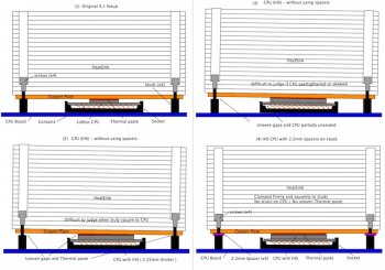
As a parting shot, I thought I'd include a schematic diagram of why there are risks and inevitable unknowns if trying to
judge the correct tightness of the heatsink screws WITHOUT using spacers. The attached schematic has 4 parts, 1) The original setup; 2) How estimating tightness makes judging thermal paste thickness almost impossible; 3) How over tightening can distort the CPU in its socket; and 4) Why spacers remove these unknowns.

Without using spacers you are trying to 'judge' that the gap between the copper base plate of the heatsink and each of the 4 studs are all exactly 2.2 mm........ nigh on impossible I suggest.

With spacers, the weight of the heatsink is taken on the studs - the CPU is sandwiched in-between. Without spacers, all the forces associated with the heatsink are borne by the CPU itself and does allow movement of the CPU and heatsink (rocking motion) associated with heating up and cooling down..... it might not be a lot, but it will be there.

There are other posts here where arguments for the care and precision of applying a thin, uniform layer of thermal paste being of paramount importance are being made without disagreement...... and yet the argument for guesswork tightening inevitably compromises that. Equally, I would suggest that sticking 3mm thick thermal pads on the CPUs is NOT a good way of keeping them cool!!

Anyway, make of this what you will, I think the argument for carefully measured spacers is bullet-proof compared to guesswork......... but this is the last comment I'll make on the matter.

Rgds,

TAMM
 

Attachments

  • Grab of 4,1 heatsink.jpg
    Grab of 4,1 heatsink.jpg
    149.8 KB · Views: 367
I have tried both methods. I destroyed 2 CPU using the heat method. Successful with the vice method for 4 cpus. I'm recommending the vice only method, not the vice and mallet method.

Is this the method that you successfully used?
https://forums.macrumors.com/threads/delidding-a-xeon-x5690-with-only-a-vice-video.1987010/

(He puts the CPU in at a slight angle, with one jaw against heat spreader edge and other jaw against CPU edge. Then squeezes vice until heat spreader pops off and CPU goes flying.)

I'm going to be trying this myself next week.

yes, except I didn't just go 1 direction until it pops. I basically went left/right/left/right until it loose enough to slide off.
I think the Xeon processor won't pop off because it is held down differently.

There are 2 things holding the IHS to the chip, the solder itself and also the black gooey rubber.

If you check out the image of a de-lidded processor, you will see that there are resistors on the surface on the left and none on the right. So make a mental note of which side you can move more and which side you can move less.

When doing the scrubbing of the solder off the chip, I recommend taping the surrounding and leaving only the metal chip exposed, that's because you are likely to "slip" during the scrubbing and you don't want to pop a resistor off the processor.
 
  • Like
Reactions: ActionableMango
When doing the scrubbing of the solder off the chip, I recommend taping the surrounding and leaving only the metal chip exposed, that's because you are likely to "slip" during the scrubbing and you don't want to pop a resistor off the processor.

Ok, will do. Thanks!
 
There actually are documented torque settings for the heatsink screws, something like 0.9nm. Looking to buy a small torque wrench if anyone is interested in selling or can offer a recommendation.
 
I didn't feel like risking my daughterboard either. I was all ready to perform the upgrade, but then I was scared-off by the fact that what can be a smooth-sailing project can also be a nightmare.

I figured I would de-lid the CPUs myself and risk them instead of my CPU sockets. I built up enough courage by watching a couple videos on it and even speaking with someone who does several X56xx chips himself. While I did have to prepare myself carefully and research the method for some time, I still felt that the actual process was very straight-forward. It wasn't difficult - rather, it was quite nerve-racking.

After successfully de-lidding both CPUs, I tested A (which worked), and then I tried putting in B as well. Couldn't get it to post like that, so I unscrewed the CPU B heatsink and then re-tightened it with less force and made sure that the screws were merely finger-tight. Worked just fine afterwards!
 
I think the caution about care is fair. The concern about removing the CPU lid is also fair.

However I just did the upgrade in 15 minutes with no issues, without mutilating the CPUs.
 
What method did you use?

I bought a pair of X5550s to practice on. It's what I have in my 4,1 so I'll take CPU A out only and instal the 'new modded' one in it's slot.
 
What method did you use?

I bought a pair of X5550s to practice on. It's what I have in my 4,1 so I'll take CPU A out only and instal the 'new modded' one in it's slot.

I got a kit on eBay. 2 CPUs, wrench, wipe, paste, washers.

The CPUs we're with lids and I left them on. You need to shave off half the knobs on the fan connector so it can stay connected with the cooling sink being slightly raised. You add 3 shims to each of the 4 rods. put in the unmodified CPU. Put paste on and fit the heat sink back on(wiped clean). Screw it back on. Worked great
[doublepost=1515408372][/doublepost]Ah, forgot the strip is also thicker than original to adjust for the shimmed height.
 
Register on MacRumors! This sidebar will go away, and you'll see fewer ads.