The fun thing is that with an app, one can just check the checkbox for the 'special' sound. Or use a selection box to select one out of a collectionas I understand this is for the emergency firmware without identity. So a special emergency firmware chime is imo helpful to separate and to warn if it was chosen.
Got a tip for us?
Let us know
Become a MacRumors Supporter for $50/year with no ads, ability to filter front page stories, and private forums.
MP 1,1-5,1 Open KickStart Project - kick new life to the cMP - polling interest
- Thread starter RolfNoot
- Start date
- Sort by reaction score
You are using an out of date browser. It may not display this or other websites correctly.
You should upgrade or use an alternative browser.
You should upgrade or use an alternative browser.
Count me in if you need testing. Couple of each 4,1 & 5,1. Can also send some donation your way to help start the project.
I have read this and its something I could donate to however can someone dumb it down for me. what exactly will it do when/if it comes to fruition.
I will maintain a list of spendings (not counting my hours). I’m willing to pay these myself in order to have a free product for every contributor, excluding shipment costs. All donations will come to the favor of the contributors, by using the donations for the shipment costs. All remaining donations are very optional!I don’t have much two offer on the programming skills. But I am willing to contribute upfront like 50-100 euro? So some test materials can be bought. Also I’m not a complete idiot and willing to experiment and alpha or beta test.
My interest would be to stay current with the latest macOS release and improve hardware support.
I just made a start with the schematic, noticed the JTAG connections to the SMC controller are also present on the little-frank. Probably Apple provided the possibility to program the SMC controller via the LF as well. Along with JTAG there is RX and TX wiring for communication with the SMC.
Good thing is the kickstart board is able to communicate over these serial lines as well but unless there's not much info on the SMC or any SMC updates, it will be a though journey to get a grip on it.
Good thing is the kickstart board is able to communicate over these serial lines as well but unless there's not much info on the SMC or any SMC updates, it will be a though journey to get a grip on it.
... from my brief reading about USB C JTAG on newer Intel systems, the answer is probably: it's all very well knowing where the JTAG connection is, but actually using it is only possible with additional Intel hardware and software, which is going to remain out of the financial reach of most non-corporate developers. Unless anyone knows more.
JTAG is a widely used common standard to program and debug microcontrollers. There are lots of JTAG tools from several vendors, one well known is J-Link. I have several JTAG tools and hooking onto a microcontroller is fairly easy (5 wires needed).... from my brief reading about USB C JTAG on newer Intel systems, the answer is probably: it's all very well knowing where the JTAG connection is, but actually using it is only possible with additional Intel hardware and software, which is going to remain out of the financial reach of most non-corporate developers. Unless anyone knows more.
In the case of the MacPro, JTAG on the LF is wired to the SMC controller. This means we can hook up a programmer / debugger to the Hitachi H8S (currently Renasas) SMC to flash it. Now reading the SMC is another story, you can bet the SMC is read protected.
Hacking a protected MCU in general is far from easy and a deep knowledge about the MCU is required. Methods involves side-channel attacks where glitches are used to destabilize the MCU into an unknown state where memory can be read. This is not the path we want to go.
On the other hand, the MCU can be erased and programmed, communication between logic board SMC and CPU board can be examined, so theoretically someone could develop a program with the same functionality as currently used by Apple (controlling fans, providing information to the CPU, detecting fault states etc). Still not easy but I’m not saying that it’s impossible.
Be careful, we dont have an image of the smc, if you erase or reprogram it you will need to swap the smc controller.
Yes, for the Mac Pro 2,1 we have one and a EFi tool to write it.
But none for a 4,1 nor 5,1.
Also we have two smc controllers on 5,1 one at the backplane and one on the cpu board.
But none for a 4,1 nor 5,1.
Also we have two smc controllers on 5,1 one at the backplane and one on the cpu board.
By the way, similar work is done for the Thinkpad Notebook (disassembling SMC firmware hoping to fix fan issue): https://forum.thinkpads.com/viewtopic.php?t=20958How do we find out more about using JTAG? (In theory in my - currently limited - understanding, we could be talking about single step debugging if the CPU with this, no? If so, ofc that _would_ be useful.)
I will send you what I have.Yes, those versions have to match in order not to have the fans spinning.
What version has the 2,1 upgrade? And how is it packed (encrypted?)
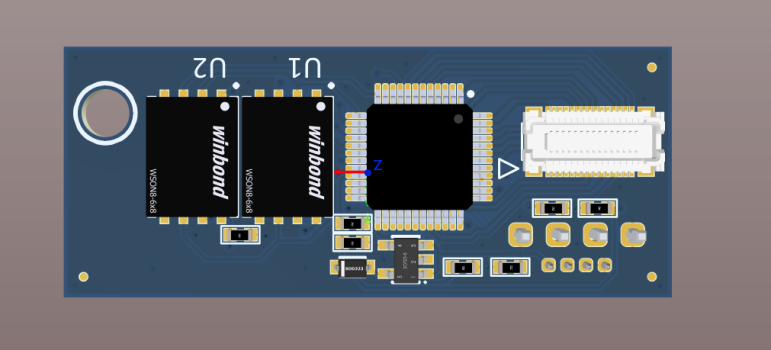
I just placed some of the proposed components on a board. It should be something like this:
- two SPI flash chips to start with (this way we can test with a default MX25L3206E and later a new large flash)
- PSoC4200L MCU to flash chips, interact with LF, select ROM etc
- USB port to interact with software on PC (HID / VCOM / Mass storage)
- SWD port to program and debug MCU
- Header for general IOs (can be configured as BootROM selection, can output to LED / Buzzer etc).
Can be done either using a switch connected to the header, a jumper or via software (USB). The new flash can even hold 16 roms so we can use 4 pins of the header to select one of them:
0-0-0-0 = software selected
0-0-0-1 = MacPro backplane rom
0-0-1-0 = rom 1
0-0-1-1 = rom 2
etc...
It's all a matter of how the on-board MCU will be programmed.
0-0-0-0 = software selected
0-0-0-1 = MacPro backplane rom
0-0-1-0 = rom 1
0-0-1-1 = rom 2
etc...
It's all a matter of how the on-board MCU will be programmed.
Only the Molex 051338-0374 and 500913-0302 seem to fit, not checked on other possible replacements yet (Hirose). Price is okay, around €1,15/pcs @ 100pcs.Ordered some connectors just before today's shipping deadline. Will see on Monday if the cheap ones fit well.
View attachment 2178189
Connection fit is solid, board won't come off easily even with a wire attached.
Noticed one issue on the current design, space between backplane and board is only about 1.5mm so the USB micro connector cannot be positioned at the bottom. Placing it at the top would need additional manufacturing steps (glueing and double pick and place) which makes it expensive.
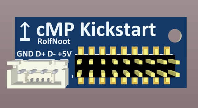
I've chosen to use a JST XH 2,54 male connector as USB cables with these connectors are cheap and easy available:
Also small boards which fits the 4x2.54mm pads with a USB micro connector are available:
Will work on the board later this week, expecting to order first batch of prototypes early next week.
Regarding USB: I was under the impression that it could be used for runtime configuration (while the device is connected via Little Frank), but the length of that USB cable seems to suggest otherwise. I guess then that the intention is to use USB just to add the BootROM image before connecting the device to Little Frank. Is that correct?
It could be used to do runtime configuration as well as detached bootrom config. The length of the cable is just a bit short. Might have to look for a bit longer cables, checked how far a 30cm cable will reach:

This cable seems to be okay (4pin version):
This one can be used as well but can potentially be reversed:
Alternatively, I could use another connector (1.25mm pitch MX Molex 53047-0410) and use this cable:
This cable seems to be okay (4pin version):
This one can be used as well but can potentially be reversed:
Alternatively, I could use another connector (1.25mm pitch MX Molex 53047-0410) and use this cable:
Last edited:
Count on me as well for financial support or testing scenarios on the Dumb User level. Crossflashed 4,1, Germany. Soldering scares the sh… outta me.
Doesn‘t Bluetooth count internally as USB? Could there be a way to connect inside case?
Doesn‘t Bluetooth count internally as USB? Could there be a way to connect inside case?
Yes. See post #43.Doesn‘t Bluetooth count internally as USB? Could there be a way to connect inside case?
There is. I’ve finally been able to secure a good quantity of the hub controller IC and revised the design to simplify a required modification to the GC-Titan Ridge card for the THB_C connection. I’ll be starting a dedicated thread soon to provide some technical documentation and keep people updated on the production.any update on the Ola having a production run?
Regarding a possible internal USB connection to the KickStart board: @RolfNoot is USB 5V needed for USB when the board is connected to Little Frank, or is D+/- enough? (I would think that Frank 3V3 already provides power but wonder if USB 5V is used for detection or something…)
Register on MacRumors! This sidebar will go away, and you'll see fewer ads.


