Become a MacRumors Supporter for $50/year with no ads, ability to filter front page stories, and private forums.

This project

  • is awesome, I like to participate wherever I can

    Votes: 14 38.9%
  • is great, I will sit back and see what becomes of it

    Votes: 17 47.2%
  • is useless

    Votes: 5 13.9%

  • Total voters
    36
  • Poll closed .
@cdf USB_Vbus is connected to the MCU for detection, however it depends on the implementation in firmware. So it's possible to enumerate (on startup) without checking for USB_Vbus and enumerate by default when USB_Vbus goes high (3V3 or more).

De LF provides 3V3 power for the board, while the board could be programmed using USB only without the need to connect it to the LF connector (using USB_Vbus). See schematic:


1682154158441.png
 
So it's possible to enumerate (on startup) without checking for USB_Vbus and enumerate by default when USB_Vbus goes high (3V3 or more).
Excellent. Enumerating on startup without checking for USB_Vbus would work then when the board is connected internally to just USB D+/-. Note that the internal connection can only ever be made before startup (no hotplugging) because there is no physical access to the internal USB header with the processor tray in place.
 
This project is extremely interesting. I would have voted

is awesome, I like to participate wherever I can​

however apart from purchasing whatever comes out of it i do not know how to help.
 
  • Like
Reactions: RolfNoot
I will maintain a list of spendings (not counting my hours). I’m willing to pay these myself in order to have a free product for every contributor, excluding shipment costs. All donations will come to the favor of the contributors, by using the donations for the shipment costs. All remaining donations are very optional!
I will donate to this. Just tell me how. I think this is a great idea and although I am able to smd solder, this is so much better than just replacing the spi onthe mb with Alex’s rebuilt bootrom
 
I will donate to this. Just tell me how. I think this is a great idea and although I am able to smd solder, this is so much better than just replacing the spi onthe mb with Alex’s rebuilt bootrom
A rebuilt firmware makes sense in any case, the board is a tool to replace the flash chip in a very clever way.

Even for the end user it could hold firmwares with different blessings to easily switch between bootloaders or difficult nvram settings like the content used for multiple displays and switching between windows and MacOs. This is sometimes tricky.
 
  • Like
Reactions: RolfNoot
Also the SMC lines (RX / TX / reset) are connected to the board (allmost all lines of the LF connector). Who knows what info is over these lines... Might be useful to detect hardware issues easily :)

I'll put the board source code online, an USB-serial bridge to SMC RX/TX implementation is easily built...
 
Noticed one issue on the current design, space between backplane and board is only about 1.5mm so the USB micro connector cannot be positioned at the bottom. Placing it at the top would need additional manufacturing steps (glueing and double pick and place) which makes it expensive.
Why not move just the pads on the top side, so that the USB micro connector can be added by the end user if needed? Leaving multiple connection options is IMHO desirable...
 
A rebuilt firmware makes sense in any case, the board is a tool to replace the flash chip in a very clever way.

Even for the end user it could hold firmwares with different blessings to easily switch between bootloaders or difficult nvram settings like the content used for multiple displays and switching between windows and MacOs. This is sometimes tricky.
Of course. Alex already rebuilt my bootrom in fact...
 
Why not move just the pads on the top side, so that the USB micro connector can be added by the end user if needed? Leaving multiple connection options is IMHO desirable...
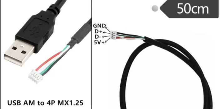
Would be an option. Note that having the connector on the other side would greatly increase the price of assembly (double sided vs single sided). Also soldering the USB micro is for most of us pretty difficult. For now I don’t see issues as the 4 wires of the cable can be soldered directly to the PCB and otherwise the USB cable with Molex can be used.
 
  • Like
Reactions: AlexMaximus
But think about that not all of us nerds can solder ;-)

Us ole dogs were raised with the soldering iron next to the computer, but not everyone can or still can.
 
  • Like
Reactions: AlexMaximus
That is why I have the 4P Molex on the board, to use with these cheap cables.

I’ll put the design files online, however I doubt if the Micro USB cable side connector will fit as the Kickstarter board is very close to the Mac board.
 

Attachments

  • AF98F4FA-5EF3-431A-8133-C4D89EA1E48F.jpeg
    AF98F4FA-5EF3-431A-8133-C4D89EA1E48F.jpeg
    155.7 KB · Views: 99
I may have not expressed myself correctly?
i meant to switch sides of the USB connector so it sits on the same side of the thru hole 4P Molex, without populating the pads with the actual part... so if someone wants to add it, and solder it manually, the pads are there. If the pads stay on the side facing the cMP LB, obviously they cant be used....Totally agree on increased cost for double pick&place
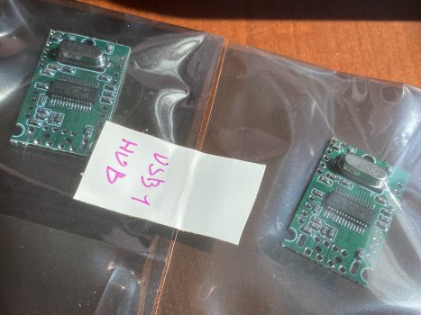
plus, I was thinking along the lines of adding a small 3-4 port usb hub to the internal port for Bt, to be used for the titan ridge TB Card, the Bluetooth upgrade and eventually your Kickstarter..
i got a few of these cards (cheaper than actually buying the parts!) and either would redraft on Diptrace a small PCB using the parts from it to build a custom board or just bodge one to be usable.
 

Attachments

  • image.jpg
    image.jpg
    432.5 KB · Views: 118
I may have not expressed myself correctly?
i meant to switch sides of the USB connector so it sits on the same side of the thru hole 4P Molex, without populating the pads with the actual part... so if someone wants to add it, and solder it manually, the pads are there. If the pads stay on the side facing the cMP LB, obviously they cant be used....Totally agree on increased cost for double pick&place
plus, I was thinking along the lines of adding a small 3-4 port usb hub to the internal port for Bt, to be used for the titan ridge TB Card, the Bluetooth upgrade and eventually your Kickstarter..
i got a few of these cards (cheaper than actually buying the parts!) and either would redraft on Diptrace a small PCB using the parts from it to build a custom board or just bodge one to be usable.

I just did a write-up on the those little 4-port USB Hubs. They work great.
Mechanically the only problem with those boards is the USB connector holes are on 2.0mm pitch making it bulky.
PicoBlade 1.25mm pitch would have been better (like MacPro's USB header).
 
  • Like
Reactions: AlexMaximus
i meant to switch sides of the USB connector so it sits on the same side of the thru hole 4P Molex, without populating the pads with the actual part
Yes, I got the idea to add the footprint to the 4p Molex side. The USB cable connector won't fit when on the bottom side and I doubt whether (with the 1mm PCB thickness) the connector will fit when placed on top.

Regarding USB hub functionality there are many solutions. I think many users won't bother to sacrifice an USB port at the backside, the cable can be easily routed through the PCIe backslots of the Mac.

Another solution is to use @cdf's Olá board

FYI, I just received the Kickstarter boards, they are (intentionally) pretty small, in order to minimize the stress on the LF connector.

Need to find some time to solder them and send them out to the first candidates for testing.

1682542773954.png


1682542585728.png

R
 
Last edited:
Yes, I got the idea to add the footprint to the 4p Molex side. The USB cable connector won't fit when on the bottom side and I doubt whether (with the 1mm PCB thickness) the connector will fit when placed on top.

Regarding USB hub functionality there are many solutions. I think many users won't bother to sacrifice an USB port at the backside, the cable can be easily routed through the PCIe backslots of the Mac.

Another solution is to use @cdf's Olá board

FYI, I just received the Kickstarter boards, they are (intentionally) pretty small, in order to minimize the stress on the LF connector.

Need to find some time to solder them and send them out to the first candidates for testing.

View attachment 2194077

View attachment 2194076
R
It’s a prototype pcb - so it’s legitim to solder the usb cable straight to the pcb. :)
 
Finally had the time to hand-solder one. 🎉

The 0.4mm Molex LF was quite a challenge but all went well.

Turns out I didn't have the original SPI-eprom (MX25L3206E) in stock and it's not quick available. It would be great if someone is able to help me with a few of these eproms, otherwise need to order them on Aliexpress.

WhatsApp Image 2023-05-06 at 21.50.05.jpeg


WhatsApp Image 2023-05-06 at 21.50.04.jpeg
 
Hi Rolf,

Great work! I will now look into your commercial projects as I am familiar with ARM but unfamiliar with PSoC.

I am interested in this project and can utilize just the bare PCB board and populate it myself to minimize your cost.
Thanks!
 
How plausible do you think it might be to use this to expand the size and scope of the bootrom? I have this fantasy of 'bankswitching' to dynamically add features and functionality stored on a second bootrom IC.
 
Just surfacing this back up above the anti Mac Pro arguments - how is the project going?
 
Register on MacRumors! This sidebar will go away, and you'll see fewer ads.