Become a MacRumors Supporter for $50/year with no ads, ability to filter front page stories, and private forums.
SMT,

I went with the bare wire ModDIY cable (as per Andree post) as I assumed you could not thread already terminated cable up into optical drive bay.

If you could then that would be great as you could avoid the molex crimping. As I said I had lots of faulty crimps to get to the eight good one.

I am sure others would like to hear how you go, as the easier we can make this process the better. What a shame Mac Pro power supply does not just have standard plugs like the pc one in your picture. Would save lots of work.

Cheers,

Zebity.
 
I saw some suggestions that the 6 pin PCI-E connector would fit through that hole, when you did yours, did it seem like that would be the case or no?

Fedex handed off my package to USPS, so doesn't look like it will get here this weekend... But once I get the cables, plan disassemble and clean and really evaluate my options... Worst case I have to remove the connectors and re attach... That is not as bad as having to crimp the pins on as you can just remove the pins from the molex shell and be sure to maintain the correct pinout...

I used to make custom length cables in my gaming PCs I built as I hated seeing cables (hence my love the of MP) :) I know how much of a pain those pins are to put on... In some cases I would not rely on the crimp and use solder to reinforce the connection...
 
Want to do a before and after on amp load... Is it safe to assume the PSU, 12V monitor in iStat showing current A draw of all the 12V coming out of the PSU? The mouse over graph scales to 80A, so sounds like it should be the best to watch...

Sensors%20Idle%20660Ti_zpsdlmotkns.png
 
Last edited:
Got my cables in yesterday, didn't go quite how I wanted... Turns out those short extensions are 16 gauge wire... No way I was getting two soldered onto the PSU... In fact getting the 16 gauge even routed out of the PSU was a challenge, very tight up against the metal (which I didn't like)... So I will have to get a splinter after all to put behind the plate...

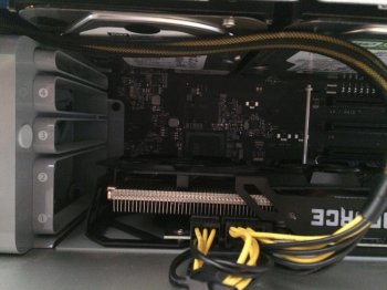
The routing was tight getting two PCI-E 8 pin cables through, but I pulled the logic board out (needed to do a thorough cleaning anyway) and was able to feed down the 6 pin the the 2 pin end of the cable, easily... The second was a little tougher as I had to push the cables up into the smaller gap next the drive door covers...

One PCI-E cable with a splitter at the card probably would have been enough, but I wanted to allow for the highest load possible... I have a 980Ti on the way and the plan is to add a second and SLI them at some point... I am going to use 6 pin of the logic board and each of the 8 pin cables added... I also didn't want to have to go back and rework if I wanted to put a card(s) in that drew more power...

IMG_1573_zpsvdzhiaus.jpg


IMG_1611_zpsnpaeh8en.jpg


IMG_1609_zpsl1symify.jpg


IMG_1588_zpsuhjdv3te.jpg


IMG_1612_zpsa43eoqye.jpg


IMG_1614_zpspqlghqtj.jpg


IMG_1617_zpsjzmootod.jpg


Now if you guys will do a sanity check for me, just wanted to be sure I have the pin out right before plugins a card in... This pin out is looking at the female end of the cable that plugs INTO the CARD, yes and not the pin out of the connector on the card itself, right? (Obviously those two pin out are mirrored of each other)... And as others stated, I connected both sense to ground...

Pulled this from the Toms Hardware article, but it doesn't mention the gender. I believe it is assumed to be the female connector, but want to be sure first. :)
Power-Supply-Fundamentals,8-L-312645-13.jpg

Edit: I have also found a lot of miss labeling of the gender of the connectors...
This labels the cable correctly as male to 2 female: Here

This is same cabled is labeled wrong as a female to 2 males: Here
 
Last edited:
@s.m.t.

Good job, bravo!

For the modular connector gender, if you are referring to this link, it is a female. It is showing the connector that connects to the video card.
 
@s.m.t.

Good job, bravo!

For the modular connector gender, if you are referring to this link, it is a female. It is showing the connector that connects to the video card.
Thanks! Yes that is the link... That was what I was assuming, but wanted to have someone double check me... :)
 
Male or female always refers to the electrical connection, not the plastic one. Your diagram refers to the female connector which is indeed the one that plugs into the card. Think of it as a dominator female.
 
Last edited:
Male or female refers to the electrical connection, not the plastic one. Your diagram refers to the female connector which is indeed the one that plugs into the card. Think of it as a dominator female.
Exactly... But I have found plenty of gender references that are wrong on the internet... So I just wanted to pass along that warning...

My voltages match so I think it is time for a load test...
 
This thread is great. Thank you to AndreeOnline for such superb informations. I have purchased and received the cable from Hong Kong and await the splice clips because I am clueless about soldering.

My question is about the connections. There are three yellow wires that connect to the 12V lines. Then there are the five black wires. Four of them connect to the GND lines. Does the fifth black wire connect to the remaining 12V line or elsewhere? Thank you.
 
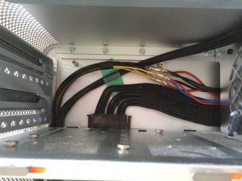
On the picture I see 8 connections, 3 to +12V and 5 to ground as it should be.

EDIT : Just got it, it seems the upper splices are on the same cable as there are 4 +12V and 4 GND cables to tap from on the logic board power cable. The sense pins are not supposed to carry much current and should be safe to connect this way.
 
EDIT : Just got it, it seems the upper splices are on the same cable as there are 4 +12V and 4 GND cables to tap from on the logic board power cable. The sense pins are not supposed to carry much current and should be safe to connect this way.
Look again, I only see 3 12v... The outer 4 connections on the Apple connector to the logic board are ground, the next inner 4 are 12v...

Annotated AndreeOnline's photo (hope you don't mind), see there are only 3 to 12v and 5 to ground the top of which has two splices...
Screen%20Shot%202015-07-04%20at%2010.51.01%20AM_zpspx671efq.png


What I would do I splice the sense pin that is part of the +2 to with one of the ground pins on the connector to one ground cable on the PSU to min load issues... That 8th pin (sense) is not widely used from what I have read, that minimizes the "effects of doubling up"...
 
Last edited:
Look again, I only see 3 12v... The outer 4 connections on the Apple connector to the logic board are ground, the next inner 4 are 12v...

Annotated AndreeOnline's photo (hope you don't mind), see there are only 3 to 12v and 5 to ground the top of which has two splices...
Screen%20Shot%202015-07-04%20at%2010.51.01%20AM_zpspx671efq.png


What I would do I splice the sense pin that is part of the +2 to with one of the ground pins on the connector to one ground cable on the PSU to min load issues... That 8th pin (sense) is not widely used from what I have read, that minimizes the "effects of doubling up"...

Thank you the annotation really helps and I wish the guys who did soldered mods also marked the photos.

I only want to direct connect the GTX 980 to the PSU to prevent the fans going mad. I don't even need the 8pin connection for the time being. All the cards faster than the GTX 980 are not quite ready for 4K so I don't need to think of them. I'll stick to 1080p gaming until truly 4K worthy GPUs are ready.
 
Hi guys!

Nice to see these mods are still alive and kicking. And as other have proven, there are many ways to skin a cat...

Out of the 8 wires that run up from the main 8-pin, only 3 are 12V lines (the yellow ones). That leaves 5 black GND.

As mentioned above (and in my original post with diagram) there are four 12V lines and four GND lines to clip onto if you do it my way. That means that one GND get double spliced. Hope this clears it up!

As I think I've stated previously: there are perhaps more elegant ways to do this. Some of the benefits I see with THIS method are: minimal dismantling, no cutting or soldering, cheap "off the shelf components" made for exactly this purpose.

Keep up the good work!
 
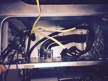
Here we go guys. Before the surgery. In 15 minutes I'll know if the Mac made it.

Edit. First plan of attack failed. I need pliers this can't be done with hands :D
 

Attachments

  • image.jpg
    image.jpg
    1.4 MB · Views: 647
Last edited:
I decided to not do the mod for now and keep the cables and clips in my tech drawer. My reasoning is that I want to wait and see what the situation is with El Cap and the next generation of graphics cards in 1-2 years. For now I'm satisfied.
 
Hi,
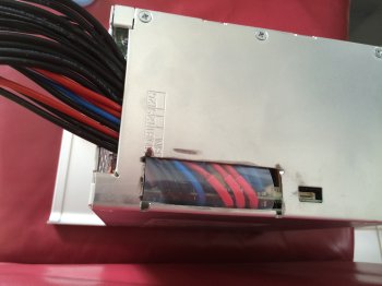
I did the project today. It wasn't as easy as I thought. I had to cut out a piece of the PSU cage as my cables were to thick to get them around the corner (1,5mm^2)
I soldered them on top of the existing joints and added some plastic protection underneath.
 

Attachments

  • 15-08-19_IMG_6010.JPG
    15-08-19_IMG_6010.JPG
    2.6 MB · Views: 937
  • 15-08-19_IMG_6012.JPG
    15-08-19_IMG_6012.JPG
    1.3 MB · Views: 843
  • 15-08-19_IMG_6014.JPG
    15-08-19_IMG_6014.JPG
    1.7 MB · Views: 902
  • IMG_6016.JPG
    IMG_6016.JPG
    826.2 KB · Views: 888
Hmmmm..... what can these safely draw when soldered directly at the PSU?

Could they be used for 8 pins on two separate cards, and the backplane 6 pins used for the 6's on the cards?

Follow? So, I guess I should really be asking, can this cable handle 300W?
 
First I tried the solderless method as described in the first post (using the moddiy cable), but that did not seem to work stable: as soon as I plugged in the 8 pin plug the power supply stayed off, no matter what.

Eventually I decided to run the cable directly from the power supply by soldering it. Unfortunately the cable now is too short but it works fine otherwise. So I'll guess I stick it in the optical bay and run extension cords from there to get the connections I need.

For now I'm running a single R9 280x on the mainboard booster cables (6 and 6->8) but I'll soon get another 280x. At that point I think I'll be providing the 6 pin power for both cards through the booster cables and the 8 pin through the freshly soldered (and then split into 2x8 pin) power cable.

My reasoning: 300W @ 12V = 25A. The ModDIY cable is 18AWG which according to some tables I found should be sufficient for up to 5-6ft. Since the cables will be mostly floating free and the 25A is dual card full load (unlikely to happen at all, and even less likely for extended periods of time) I think I should be fine. Can anyone confirm this?

edit: took the gamble and it did not work reliably. Power-wise it seems to work fine. Unfortunately crossfire seems to be a no-go, as long as there is an EFI component in the cards BIOS involved: Windows doesn't even boot to the desktop with CF enabled. As soon as I switch to an alternate BIOS (legacy, no boot screen) and boot into Windows CF works as intended.
 
Last edited:
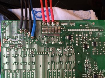
Hello all, Today I took the plunge and hard wired in 3 ground and 3 12v to the Power supply... would have done the 5 ground thing but long story.... and pain in the @$$ to get the solder to work well...

anyway installed to GTX 680s want to run SLI in windows boot camp have it all setup but no options to enable SLI.... is there a boot camp driver or some such thing I need to get SLI to work?

thanks

oh and system specs are as follows

Dual 5660s 48gb ram, 2 2TB 1 1 TB and 2 250gb samsung SSDs along with the dual GTX 680s

again thanks
 
SLI needs an SLI compliant motherboard which the Mac Pro doesn't have. There used to be a hack that allowed to do SLI on any motherboard, I don't remember the name though. It needed to be updated with each new driver release and the last time I checked it was not under active development and thus not compatible with the latest nVidia drivers. You might want to check if there's a newer or other hack.
 
Register on MacRumors! This sidebar will go away, and you'll see fewer ads.