Become a MacRumors Supporter for $50/year with no ads, ability to filter front page stories, and private forums.
Yes, one internal 6 pin can supply the 8 pin connector of a 980ti, there's two of them. The other two 6 pin connectors can be supplied by SATA power. No mod, no external PSU, just four cheap adapters. I think simplicity was the word.

i for one would not recommend trying to pull 150W off of the 6pin, let alone two 150Watts. Yeah, i understand the load balancing and having the power cut off protection, but just looking at most (if not all) 6-to-8pin adapters, they're practically just 18AWG wires and then the extra two ground pins of the 8pin (the +2 part of the adapter) is going to try to pull off that needed 150W through another one of the 3 existing ground pins.

It may work, but really very very close to the shutdown limit, and there are plenty of reports that the 980Ti can shutdown the Mac Pro, just not every single card will do. However, also not every single card (even the none OC card) won't trigger the shut down protection.him.

Yup! different board designs can ask for less or more power from the connectors, and it all depends on what the manufacturer decides on with their hardware and firmware/bios limits. One set of RX 480s that I had required single 8 pin, and the 6-to-8pin adapter worked for light photoshop and internet browsing but always shut off under any incremental load. Another set that I exchanged them for had only 6-pin requirement and that's never caused me any shutdown issue.

Well I've checked and there are effectively a few users reporting shutdowns, that's still something to be prepared for but it's worth a try. Now as he doesn't feel comfortable doing the mod himself I'd rather advise him to ask for help doing it rather than using an external PSU. It's a dirty and ugly hack and it's not safe to use on a daily basis unless properly done. This thread has freed us from using this hack so it's hard to recommend it here.

Yeah this thread is pretty awesome from shedding light on what can be done when it comes to powering extra beefy GPUs. I just finished this mod, but the only difference I did was that I used 12AWG wires and only tapped into 4 wires, two positives and two grounds. Everything works, but one important note Im going to make is that the two 390X cards that I used and stress tested maxed out at 986W but consistently stayed at 900W.

Screen Shot 2016-11-15 at 6.32.38 PM.png


PCIe Slot 1 = 87W
PCIe Slot 2 = 73.44W
6Pin booster 1= 46.68W
6Pin Booster 2 = 54W
PSU 12V = 817W​

The above is just a momentary snapshot during stress testing, and the values did go up and down but this one is the most consistent values I've got.


Since itdk92 stated that it will be unacceptable for his working environment. I personally won't recommend this config to
him.

I probably wouldn't suggest doing a bunch of dongles and adapters either based on what i've personally seen. The beauty of getting the power directly from the PSU through this mod or using an external PSU is that the biggest risk the user will be facing is replacing a PSU incase of a crazy consitent overload because the system board is bypassed entirely for the high amp power draws.

So what you're telling is that you have to open the PSU and solder inside, which is what the internal mod is about. You would also need to make electrical connections between the two PSUs to synchronise their startup or start your external PSU manually (which means having physical access to it).
Hahaha yeah I was actually planning to do that and already had laid out and tested what I needed to do. I was thinking about the internal 2nd PSU method because I wanted to max out the powerdraw potential and wanted to bypass the MacPro's psu circuitry as much as possible. A small 12v or 5v relay triggered to connect the ePSU's "power sense" pins did the trick, so as soon as the macpro power comes on, the relay clicks and turns on the psu also. Wiring the AC power cables internally also would keep it "clean" per se. Just my low standards, function over form thinking.

No mod, no external PSU, just four cheap adapters. I think simplicity was the word.

Unfortunately I did go overboard on that plan and forgot that simplicity was the word. Sorry, I just got a little excited there o_O
 
Last edited:
would fans go crazy? (top much power drawn from the sata ports)

Not sure about the fan, because it seems both the SATA port and total consumption won't do anything to the fan. I only know the PSU fan and PCIe fan are sensitive to the 6pins loading.

Anyway, it's easy to control the fan by using MacsFanControl. Just set a fan profile base on PSU temperature on the PSU fan, and the PCIe fan base on the PCIe ambient temperature. Then the fans should keep your Mac cool, safe, and not too noisy.
 
A basic question for those who actually have done this mod: does it matter how the ground cables of the new PCI plug are connected to the ground cables coming out of the PSU? And could maybe someone educate me on the role of the ground/sense pins?
 
A basic question for those who actually have done this mod: does it matter how the ground cables of the new PCI plug are connected to the ground cables coming out of the PSU? And could maybe someone educate me on the role of the ground/sense pins?

The 2 extra ground/sense pins in the 8-pin connector essentially inform the graphics card that 150 watts are available from the other 6 pins instead of the normal 75 watts.

In the past I assumed it did not matter how the ground pins were wired since I had assumed that they all went to a common ground anyway, but I do remember some discussion about certain 6-to-8 pin adapters being wired incorrectly, so now I'm not sure.
 
The electrical current flows in a circuit (think of a loop) in which the power supply acts like a pump pushing the current, so the current flows from the power supply to the supplied devices and then back to the PSU where it will be pumped again. In a circuit the current that comes out of a generator always goes back to that same generator.

So in our mod, the current flows from the +12V to the graphics card where most of its potential energy (the voltage) is consumed, then it goes back to where it came from through the ground, so there is as much current going through the +12V wires and the ground wires. As such it is important that both are properly and solidly connected to the PSU with sufficiently thick connections as we are dealing with important currents here. If an electrical connection is not thick enough for the amount of current it is carrying, it heats up and eventually burns. Connections can become weak points and must be made properly.
does it matter how the ground cables of the new PCI plug are connected to the ground cables coming out of the PSU?

It's true that in most devices using a metallic chassis or case, the chassis or case is connected to the PSU ground. I assume that by asking that question you want to know if one can connect the graphics card's ground to another ground connection (for example on any PCB or ground wire nearby) or directly to the chassis. Because we're dealing with a lot of current here I'd advise against doing so.

You don't always know how thick a ground connection is to the PSU and thus how much current it can handle without heating. Every ground connection inside your mac is dimensioned relatively to the amount of current it is supposed to carry. Adding more current to an existing connection may be a risk unless you know what you're doing. Tapping into the thicker wires directly coming out of the PSU is safe because those are meant to carry the whole load of the machine. You should still split the load across the wires as was done in the OP.

Also there's no perfect electrical connection which means any ground connection will still have a tiny resistance, and the current flowing through it will generate small parasite signals which can disturb neighboring circuits sharing the same ground connection. By making the ground current flow through another route, you may disturb other parts of the machine.

The safest way is to firmly connect both the +12V and the GND of your graphics card using a dedicated and properly dimensioned connection the closest possible from the PSU.
And could maybe someone educate me on the role of the ground/sense pins?

It is possible to plug a 6 pin connector into an 8 pin connector and some graphics cards allow to be powered this way. The sense pins don't carry much current but allow the graphics card to differentiate a 6 pin supply from an 8 pin supply.
 
Last edited:
  • Like
Reactions: Macschrauber
A basic question for those who actually have done this mod: does it matter how the ground cables of the new PCI plug are connected to the ground cables coming out of the PSU?

The cMP's PSU ground cables are split into four 12AWG stranded cables. The positive leads are also split into four. However, If you see how the connections from the PSU to the mobo looks like, the four grounds join up again in 2 pairs, and so did the positive ends. There can be many reasons why apple this this, but few that I see to fit their MO:

1. Cost: Its cheaper to use more of the the smaller 12AWG wire than the heavier wires
2. Design & manufacturing: Its easier to bend and manipulate thinner 12AWG to satisfy apple's design needs versus thicker and heavier wires. If you look at the psu cable to the mobo, they're actually flattened out instead of coming out as a round bundle, which allowed them to provide 980W of useable power through a very small space.
3. Efficiency, Ampacity, Code: the NEC 240.4(D) back in '02 standard code dictates that small conductors of of 12AWG be limited to 20A max. Now apple's designed to have 4 wires to carry load at 12V, and each wire are rated for 20A, so 4 x 20A x 12V = 960Watts. Now Apple rates the PSU at 980Watts, which is fine considering that extra 20 watts is only within 2% of the maximum rated capacity of the cables. Using cables thicker or thinner than the 12AWG would either be a waste of copper or waste of insulation.

But I digress. If you are tapping on the PSU cables directly, you'll need to supply a max of 150W (per GPU) so if you know you need only one gpu, then you can just tap in to one ground and one power. Do the same for the 2nd PSU to different lead wires. Since most PCIe extension cables are 16awg or less, you can just bunch up all the grounds together and connected it to one psu ground, and all the power wires (usually yellow on aftermarket) together to one power wire on the PSU.


And could maybe someone educate me on the role of the ground/sense pins?

As the others already mentioned, the sense pin allows the card to detect or "sense" the presence of an 8 pin pcie, and it will then try to draw 150W off of that connector. So basically the connector has 3 power wires and 5 ground wires, which seems uneven. But each of the 3 power wire (typically 18AWG) is rated to handle 5.6A which totals to 201 Watts so they can safely carry the 150W maximum allowed draw on the 8pin. The other two wires just come in for modularity. Oh, and if it helps the confusion, the 8 or 6 pin PCIe cables don't actually carry data, only power so as long as the right voltage and the right grounding/power is supplied to the proper pins, the card will be happy.
 
Last edited:
Btw! Just looked at the back of my mac pro 4.1/5.1 and realised that if i want to put 2 GPUs in slot 1 and 2 respectively, I'll lose slot 3!

This sucks :D

Anybody has a workaround for this?
 
Btw! Just looked at the back of my mac pro 4.1/5.1 and realised that if i want to put 2 GPUs in slot 1 and 2 respectively, I'll lose slot 3!

This sucks :D

Anybody has a workaround for this?

1)use a PCIe extension cable to utilise slot 3
2) use PCIe extension to run the GPU in slot 2
3) install the GPU in slot 4 (block the HDD bay)
4) get a single slot card if possible

So, the choices are basically bad or very bad :D
 
1)use a PCIe extension cable to utilise slot 3
2) use PCIe extension to run the GPU in slot 2
3) install the GPU in slot 4 (block the HDD bay)
4) get a single slot card if possible

So, the choices are basically bad or very bad :D


Well, actually the 1st does not sound like a bad option at all!

Anybody tried this?

I could put the Pcie ssd adapter there and maybe fit it in the cd drive slot..mmm
 
Also, I was just looking at the mod and thinking if there actually is a certain scheme to connect the cable, or if it's just like

1 random fat cable of the PSU -> 1 random thin cable of the 2x8pin cable

is it that simple?
[doublepost=1481252488][/doublepost]Ok I just read all of the comments carefully and notices the 12v and ground thing. I am soon trying this mod :)
 
Hi there,

I tried using the lowest profile PCIe extension cable in slot 3 to sort of "get out from under the gfx". But even with my pretty low profile cable, it wasn't possible to seat the slot 2 graphics card properly, unfortunately.

If you're using SSDs in bay 2, 3 and 4 it might be possible to get a card into PCIe slot 4. I wanted to test this but haven't yet. By eyeballing it, it MIGHT be possible but I'm not sure. Using a R9 Fury Nano, you'd only need to clear bay 3 and 4 (provided it fits thickness wise).

My RX 480 is semi weak sauce, but they are pretty cheap and I'm thinking real life penalty from using slot 4 might be minimal. It could be worth it to try getting a dual card config up and running while maintaining PCI-SSD and USB3.

IMG_0309.jpg IMG_0310.jpg
 
Last edited:
Hi there,

I tried using the lowest profile PCIe extension cable in slot 3 to sort of "get out from under the gfx". But even with my pretty low profile cable, it wasn't possible to seat the slot 2 graphics card properly, unfortunately.

If you're using SSDs in bay 2, 3 and 4 it might be possible to get a card into PCIe slot 4. I wanted to test this but haven't yet. By eyeballing it, it MIGHT be possible but I'm not sure. Using a R9 Fury Nano, you'd only need to clear bay 3 and 4 (provided it fits thickness wise).

My RX 480 is semi weak sauce, but they are pretty cheap and I'm thinking real life penalty from using slot 4 might be minimal. It could be worth it to try getting a dual card config up and running while maintaining PCI-SSD and USB3.

View attachment 677092 View attachment 677093


Hey.

I was wondering pretty much all night about how to configure the damn pcie slot 3 :D

I came to the conclusion that an extender is simply not possible since my MSI RX480 8G covers slot 3 so much, that there is no physical space to actually connect stuff to slot 3

So I tested the GPU in slot 4 (Heaven) and got pretty much similar results to slot 1 (!!) which might be a coincidence, or a rule (had tested three times each setup)

MSI GAMING X RX480 8GB - HEAVEN benchmark
Slot 1 (x16) // Extreme setting // 41.1fps - 1050 score
Slot 4 (x4) // Extreme setting // 40.7fps - 1026 score


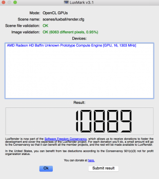
And here is Luxmark:
 

Attachments

  • LUX-SLOT4.png
    LUX-SLOT4.png
    290.7 KB · Views: 240
Last edited:
Hey.

I was wondering pretty much all night about how to configure the damn pcie slot 3 :D

I came to the conclusion that an extender is simply not possible since my MSI RX480 8G covers slot 3 so much, that there is no physical space to actually connect stuff to slot 3

So I tested the GPU in slot 4 (Heaven) and got pretty much similar results to slot 1 (!!) which might be a coincidence, or a rule (had tested three times each setup)

MSI GAMING X RX480 8GB - HEAVEN benchmark
Slot 1 (x16) // Extreme setting // 41.1fps - 1050 score
Slot 4 (x4) // Extreme setting // 40.7fps - 1026 score


Promising, but I will test it with Luxmark soon

(1050-1026)/ 1026 = ~2.3%

Very similar to my result, 2.4%

https://forums.macrumors.com/thread...mac-with-2-d700s.1732849/page-5#post-21722712

It's amazing how little the extra 12 lane can do on these mid level GPUs.
 
  • Like
Reactions: itdk92
Did you completely clear out HD bays 2-4 or did you get the card in there with small SSDs still in place?

So atm I only had an SSD in bay one, mounted with Angelbird mount + 1TB backup on slot 4.
As a temporary solution, I get 2 x SATApower and put them in an 8pin from bay 2 and 3 for the RX480.

As soon as I put the RX in slot 4 I had to actually clear SATA slot 2,3 and 4.
I am convinced I could maybe put a bare SSD in SATA slot 2 but I don't know, cause man the gap is so small. I am even considering getting a reference RX480 card, since it should be 5mm less in height. (LOL that was actually what I purchased, but they sent the MSI GAMING X instead)

Also, storage wise, I think I will put 2 SSD's in the optical bay, and connect them to the FASTA PRO
I will then use SATA bay 1 and 2 to power one of the RX480, and the double mini6pin for the other RX480

I don't need more than 2 SSD's but it's super annoying to lose SATA bay 3 and 4, but I guess I'll think of a solution.
Could use a 4-6TB time machine HDD in there.
 
Question for AndreeOnline,

Are you booting from the 1TB SSUBX? I can't find this info anywhere or if these chip are AHCI compatible or not?

Thanks!
-Chris
 
You tapped the power cable while the PSU was still in the case? You are a hero, sir, that must've been a huge pain.

I tapped the drive power cable in my MP 1,1 (granted, it was with a soldering iron) and it was a huge pain in the ass even though that one can stretch out of the case a bit.

Also, if the Mac Pro is 980 watts with 1 rail, you could easily accommodate 2 high power GPUs. As far as the GPU extender, you could consider removing the heatsink from a non-standard GPU and modifying it to fit. Alternatively, you could do something like this only instead of hard drives, put the card there:
http://barefeats.com/hard128.html
DX4_1.jpg

DX4_3.gif
 
  • Like
Reactions: Bigjohncfl
Well, actually the 1st does not sound like a bad option at all!

Anybody tried this?

I successfully used a riser to run two reference 680s along with a sonnet tempo and an apricorn card. The riser from slot three spanned the tempo and I wired my apricorn card to the bottom of the HD4 bay. It was packed and the PCIe screw bracket definitely became an asset in securing everything but I didn't have any issues.
 
  • Like
Reactions: h9826790
I successfully used a riser to run two reference 680s along with a sonnet tempo and an apricorn card. The riser from slot three spanned the tempo and I wired my apricorn card to the bottom of the HD4 bay. It was packed and the PCIe screw bracket definitely became an asset in securing everything but I didn't have any issues.


have any link to the raiser?

apparently I could find loads of them but looks like they are just cheap stuff..
 
Register on MacRumors! This sidebar will go away, and you'll see fewer ads.