Become a MacRumors Supporter for $50/year with no ads, ability to filter front page stories, and private forums.

Dadioh

macrumors 65816
Original poster
Feb 3, 2010
1,123
36
Canada Eh?
Dadioh- there is a green light when the MagSafe is plugged in. I think the first place I need to check is what could be stopping the battery from putting out power to the board and stopping it from taking power from the board to charge. Some things I forgot to mention in the first post are that I have 3.4v at the G3Hot pad that others have used to start their machines by bridging it to the one next to it when the MagSafe is plugged in. The machine is also unresponsive to your SMC bypass mentioned at the beginning of the thread.

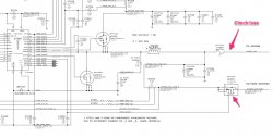
Check the fuse and the FET indicated below and let us know if voltage is appearing on the other side of them.
 

Attachments

  • power.jpg
    power.jpg
    117.3 KB · Views: 1,342

jcrandall23

macrumors newbie
Nov 15, 2011
24
0
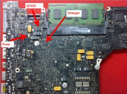
Thanks for the help so far. Can anyone guide me to where the fuse and FET mentioned can be found on the board?
 

Dadioh

macrumors 65816
Original poster
Feb 3, 2010
1,123
36
Canada Eh?
Thanks for the help so far. Can anyone guide me to where the fuse and FET mentioned can be found on the board?

I grabbed a picture from earlier in the thread and labeled the fuse and FET.
 

Attachments

  • MBP13_Charger.jpg
    MBP13_Charger.jpg
    157 KB · Views: 1,776

jcrandall23

macrumors newbie
Nov 15, 2011
24
0
Ok: with magsafe plugged in and battery unplugged, I get 12.6v on either side of the fuse that seems to cycle from 12.6v to 0 and back. Same thing on the FET. With magsafe and battery, I get a consistent 11.6v on both sides of the fuse, as well as 11.6v on the left pad of the FET and, counting forward from the battery connector 11.6v on pads 1,2, and 3 of the FET, with 4.7v on the farthest one from the battery connector.
 

Dadioh

macrumors 65816
Original poster
Feb 3, 2010
1,123
36
Canada Eh?
Ok: with magsafe plugged in and battery unplugged, I get 12.6v on either side of the fuse that seems to cycle from 12.6v to 0 and back. Same thing on the FET. With magsafe and battery, I get a consistent 11.6v on both sides of the fuse, as well as 11.6v on the left pad of the FET and, counting forward from the battery connector 11.6v on pads 1,2, and 3 of the FET, with 4.7v on the farthest one from the battery connector.

Does the magsafe LED also cycle at the same time? The reason I ask is that the charger circuit tells the SMC that it is happy by asserting 3.3V on the CHGR_ACOK line. That, in turn, will turn the magsafe LED on. If the charger circuit is cycling and trying to turn on then it may be asserting and removing that 3.3V and should result in the LED flashing (I assume). This is with no load however since you say it behaves this way with battery unplugged.

Then, with battery plugged in it is constant 11.6V but that is too low. The charger should be upwards of 12.4V to charge the battery. Sounds like something is wrong in the charging circuit. Check the FET's Q7030 and Q7035 to make sure they are OK. They are on the backside of the board in the approximate location behind the charger device. The resistance from Gate to Source and Drain to Source should be in the kohm or Mohm ranges. If they are blown you may see tens of ohms. I wrote down typical values but I am not near my workshop right now. Just going from memory.

If one of those FETs is blown the charger will not be able to drive the charge voltage.
 

jcrandall23

macrumors newbie
Nov 15, 2011
24
0
The magsafe stays green the whole time. I'll pull the board later tonight and check those FETs you mentioned. Thanks again for the help.
 

macattack600

macrumors member
Jan 7, 2012
31
0
SMC bypass question

At the start of the thread the SMC bypass was explained. I was wondering what are the negative effects of running the logic board that way besides the fans eventually going dead from high speed. Does it ruin the smc if it is good. Does it permantely stay that way upon every boot? If you happend to run it that way on a perfectly function Macbook what would be the negative effects. Thanks.
 

longcoo817

macrumors member
Oct 23, 2011
30
0
Dallas TX
i have a macbook white unibody that was full of debris and the heat sync was clogged with dust. It might have overheated till it died not sure but i can see it happening with all the debris on the board. Im only getting 3.1v at the g3hot is there anything i should be looking thetas causing it to be at 3.1v. It still charges but it also make a little frequency noise but it goes away if i disconnect the wifi cable
 
Last edited:

peislander

macrumors member
Jun 17, 2011
84
0
P.E.I. Canada
Hello.And i'm sorry to bother you.Macbook aluminium.Starting only from battery.No light on adapter,no charging.I take only 0,27 volts on pin 2,4 at magsafe board.Fuses near battery and underside logic board near magsafe board plug give 0 volts.I bought new magsafe board from ebay.Nothing changes.Magsafe adapter gives 6.55v on both 2,4 pins.If i short pin 2,3 or 3,4 adapter raises volts to 16.95.Please help me.I will give any additional information you want.:(

Did you ever figure this out?I got 2 13 inch Macbook aluminum that will only work with a charged battery.Will not charge or power up with power plug.I checked most components mentioned in this posting & they seem good.Thanks
 

cmdrdata

macrumors 6502
Jun 10, 2011
377
2
Dallas, Texas, USA
At the start of the thread the SMC bypass was explained. I was wondering what are the negative effects of running the logic board that way besides the fans eventually going dead from high speed. Does it ruin the smc if it is good. Does it permantely stay that way upon every boot? If you happend to run it that way on a perfectly function Macbook what would be the negative effects. Thanks.

I don't see how this would affect the system negatively other than fan noise and its premature wear. If there is something that is not working already, it is off purse will remain that way. I don't recall if this method bypass the system power on check called POST (power on self-test).

----------

i have a macbook white unibody that was full of debris and the heat sync was clogged with dust. It might have overheated till it died not sure but i can see it happening with all the debris on the board. Im only getting 3.1v at the g3hot is there anything i should be looking thetas causing it to be at 3.1v. It still charges but it also make a little frequency noise but it goes away if i disconnect the wifi cable

The other day I fixed/spliced a pair of wifi cable connector (canibalized an old set of cable so I don't haves to disassemble the display half)) because the shielding from the tiny coax cable have pulled up from the connector crimp. You may want to check that as the source of the freq. noise.

----------

Did you ever figure this out?I got 2 13 inch Macbook aluminum that will only work with a charged battery.Will not charge or power up with power plug.I checked most components mentioned in this posting & they seem good.Thanks

Peislander, did you get 12v at the fuse by the battery when attempting to power on using just the magsafe? If you don't have this 12v, then battery will not charge and the system will not even begin to power on. From there you have to back track all the way to the DCIN board. The magsafe sense circuit will only output 16.5/18.5 volt if there is a load on its power line, otherwise it will default to low current, open voltage of around 6v. Without the battery, G3HOT will also not be present if magsafe is not enabling it's power output.
 

peislander

macrumors member
Jun 17, 2011
84
0
P.E.I. Canada
I don't see how this would affect the system negatively other than fan noise and its premature wear. If there is something that is not working already, it is off purse will remain that way. I don't recall if this method bypass the system power on check called POST (power on self-test).

----------


The other day I fixed/spliced a pair of wifi cable connector (canibalized an old set of cable so I don't haves to disassemble the display half)) because the shielding from the tiny coax cable have pulled up from the connector crimp. You may want to check that as the source of the freq. noise.

----------


Peislander, did you get 12v at the fuse by the battery when attempting to power on using just the magsafe? If you don't have this 12v, then battery will not charge and the system will not even begin to power on. From there you have to back track all the way to the DCIN board. The magsafe sense circuit will only output 16.5/18.5 volt if there is a load on its power line, otherwise it will default to low current, open voltage of around 6v. Without the battery, G3HOT will also not be present if magsafe is not enabling it's power output.[/QUOTE)

On the first board I got 12.29 at fuse & 3.43 at G3hot with just power cord attached
.EDIT;I think its in the One wire Over Voltage Protection circuit.I got only 3.43 volts on pin 6 of Q6920.I tested voltage on board with magsafe green but no charge I get 3.4v on pins 1 3 4 & 6.On pins 2 & 5 I get 8.46v.Q6910 I get between 15.86 & 16.87v on pins 4 5 & 6 only.Other board I get 0v pin 1,3.26v pin 2,16.86v pin 3,16.87v pin 4,12.2v pin 5,0v pin 6.On Q6915 0v pin 3..Other board shows 8.46 pin 3.On u6915 no power on any pins.Other board pin 1 8.38v,pin 3 3.39v,pin 5 16.86v.I already replaced q6910 but it was used.Where to check next?Starting to feel safer testing powered board with smaller probes.I had fried a few with my older probes.
Would u7060 (TL331)cause it not to power up on magsafe?It seems to test good except I get a beep in diode mode both directions between pins 2 & 5.On good boards I only get beep in one direction.I bet if I pull u7060 & bench test it It will test good.& I'll have the same results testing pads on board.Thats what I planned on doing next but was looking for a good TL331 to replace it with.I see the LM397(got some) looks similar but on data sheets It looks like the ib on the TL331 is negative & on LM397 isn't .Please explain...
On the second board u7000 heats up so I don't leave plugged in too long.I already replaced it with same results.Still heats up.This was one of them seedy ebay deals bought laptop for parts or repair but nothing mentioned about attempted repair on mobo.Noticed 2 mosfets, 4 resistors & 3 caps gone from mobo.I'm just happy to get it to boot from battery.It still has no sound or backlight.Yes a work in progress.Practice the soldering skills.HAHA
Thanks again for any help or ideas
 
Last edited:

cmdrdata

macrumors 6502
Jun 10, 2011
377
2
Dallas, Texas, USA
[QUOTE-peislander] On the first board I got 12.29 at fuse & 3.43 at G3hot with just power cord attached
.EDIT;I think its in the One wire Over Voltage Protection circuit.I got only 3.43 volts on pin 6 of Q6920.I tested voltage on board with magsafe green but no charge I get 3.4v on pins 1 3 4 & 6.On pins 2 & 5 I get 8.46v.Q6910 I get between 15.86 & 16.87v on pins 4 5 & 6 only.Other board I get 0v pin 1,3.26v pin 2,16.86v pin 3,16.87v pin 4,12.2v pin 5,0v pin 6.On Q6915 0v pin 3..Other board shows 8.46 pin 3.On u6915 no power on any pins.Other board pin 1 8.38v,pin 3 3.39v,pin 5 16.86v.I already replaced q6910 but it was used.Where to check next?Starting to feel safer testing powered board with smaller probes.I had fried a few with my older probes.
Would u7060 (TL331)cause it not to power up on magsafe?It seems to test good except I get a beep in diode mode both directions between pins 2 & 5.On good boards I only get beep in one direction.I bet if I pull u7060 & bench test it It will test good.& I'll have the same results testing pads on board.Thats what I planned on doing next but was looking for a good TL331 to replace it with.I see the LM397(got some) looks similar but on data sheets It looks like the ib on the TL331 is negative & on LM397 isn't .Please explain...
On the second board u7000 heats up so I don't leave plugged in too long.I already replaced it with same results.Still heats up.This was one of them seedy ebay deals bought laptop for parts or repair but nothing mentioned about attempted repair on mobo.Noticed 2 mosfets, 4 resistors & 3 caps gone from mobo.I'm just happy to get it to boot from battery.It still has no sound or backlight.Yes a work in progress.Practice the soldering skills.HAHA
Thanks again for any help or ideas[/QUOTE]

I do not have a schematic for your system and cannot answer specific info that you asked. For example the 2 or 3 schematics that I have does not show any Q6920 anywhere (Adobe pdf file search)
 

peislander

macrumors member
Jun 17, 2011
84
0
P.E.I. Canada
I don't see how this would affect the system negatively other than fan noise and its premature wear. If there is something that is not working already, it is off purse will remain that way. I don't recall if this method bypass the system power on check called POST (power on self-test).

----------


The other day I fixed/spliced a pair of wifi cable connector (canibalized an old set of cable so I don't haves to disassemble the display half)) because the shielding from the tiny coax cable have pulled up from the connector crimp. You may want to check that as the source of the freq. noise.

----------


Peislander, did you get 12v at the fuse by the battery when attempting to power on using just the magsafe? If you don't have this 12v, then battery will not charge and the system will not even begin to power on. From there you have to back track all the way to the DCIN board. The magsafe sense circuit will only output 16.5/18.5 volt if there is a load on its power line, otherwise it will default to low current, open voltage of around 6v. Without the battery, G3HOT will also not be present if magsafe is not enabling it's power output.

[QUOTE-peislander] On the first board I got 12.29 at fuse & 3.43 at G3hot with just power cord attached
.EDIT;I think its in the One wire Over Voltage Protection circuit.I got only 3.43 volts on pin 6 of Q6920.I tested voltage on board with magsafe green but no charge I get 3.4v on pins 1 3 4 & 6.On pins 2 & 5 I get 8.46v.Q6910 I get between 15.86 & 16.87v on pins 4 5 & 6 only.Other board I get 0v pin 1,3.26v pin 2,16.86v pin 3,16.87v pin 4,12.2v pin 5,0v pin 6.On Q6915 0v pin 3..Other board shows 8.46 pin 3.On u6915 no power on any pins.Other board pin 1 8.38v,pin 3 3.39v,pin 5 16.86v.I already replaced q6910 but it was used.Where to check next?Starting to feel safer testing powered board with smaller probes.I had fried a few with my older probes.
Would u7060 (TL331)cause it not to power up on magsafe?It seems to test good except I get a beep in diode mode both directions between pins 2 & 5.On good boards I only get beep in one direction.I bet if I pull u7060 & bench test it It will test good.& I'll have the same results testing pads on board.Thats what I planned on doing next but was looking for a good TL331 to replace it with.I see the LM397(got some) looks similar but on data sheets It looks like the ib on the TL331 is negative & on LM397 isn't .Please explain...
On the second board u7000 heats up so I don't leave plugged in too long.I already replaced it with same results.Still heats up.This was one of them seedy ebay deals bought laptop for parts or repair but nothing mentioned about attempted repair on mobo.Noticed 2 mosfets, 4 resistors & 3 caps gone from mobo.I'm just happy to get it to boot from battery.It still has no sound or backlight.Yes a work in progress.Practice the soldering skills.HAHA
Thanks again for any help or ideas

I do not have a schematic for your system and cannot answer specific info that you asked. For example the 2 or 3 schematics that I have does not show any Q6920 anywhere (Adobe pdf file search)[/QUOTE]

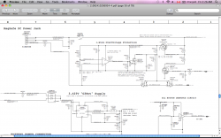
Here's is the schematic i'm using.
I just googled ntud3127cxxg & its there for download.I'll attach the link so everyone can see.Thanks
http://www.go-gddq.com/upload/2011-09/11092410206934.pdf
 

Attachments

  • picture for crm data.png
    picture for crm data.png
    272.3 KB · Views: 676
Last edited:

debo160

macrumors newbie
Jan 24, 2012
16
0
WOW I'm learning so much. I am a newbie and have revived a few boards. After reading every post in the back light tread I found this one by accident. Anyway I have a MBP 13 that will get green lights on the battery indicator as well as the magsafe. When I power it up there is a quick burst of power to the hard drive only. You can hear it boot for maybe 5 seconds then it shuts off. I can't get it to do anything past that. I was wondering what would be the next steps to take. I also have a smd & bga rework station. I do need to get the smaller leads for the multimeter but other than that i think I'm ready to go. Dadioh and others are doing a great job here. I feel like I'm back in school. I have been out for a while so these are my refresher courses. Thanks
 

Dadioh

macrumors 65816
Original poster
Feb 3, 2010
1,123
36
Canada Eh?
WOW I'm learning so much. I am a newbie and have revived a few boards. After reading every post in the back light tread I found this one by accident. Anyway I have a MBP 13 that will get green lights on the battery indicator as well as the magsafe. When I power it up there is a quick burst of power to the hard drive only. You can hear it boot for maybe 5 seconds then it shuts off. I can't get it to do anything past that. I was wondering what would be the next steps to take. I also have a smd & bga rework station. I do need to get the smaller leads for the multimeter but other than that i think I'm ready to go. Dadioh and others are doing a great job here. I feel like I'm back in school. I have been out for a while so these are my refresher courses. Thanks

Welcome to the thread. I was thinking at some point I should grab a lot of the generic info and put it all in the first post to make it easier for people to learn the basics without needing to read the whole thread. Finding the time is the problem :(

I have had boards that would not chime but would activate the hard drive or DVD but I can't recall if there was a specific issue. The fact that it shuts down so quickly seems to indicate to me that there is something that is being detected by the SMC that causes it to shut the board down. Could be a voltage, current, or temperature. If it is a liquid spill board then close examination may be the best start. Do you have a binocular microscope? Very valuable for any repair on these boards. Probably about a $300-$500 investment but well worth it.
 

cmdrdata

macrumors 6502
Jun 10, 2011
377
2
Dallas, Texas, USA
[QUOTE-peislander] On the first board I got 12.29 at fuse & 3.43 at G3hot with just power cord attached
> This is GOOD.

I think its in the One wire Over Voltage Protection circuit.I got only 3.43 volts on pin 6 of Q6920.I tested voltage on board with magsafe green but no charge I get 3.4v on pins 1 3 4 & 6.On pins 2 & 5 I get 8.46v.
> Q6920 is GOOD

Q6910 I get between 15.86 & 16.87v on pins 4 5 & 6 only.
> This is BAD. Pin 6 should be around 0v when the SMC sends a signal saying SMC_BC_ACOK. When this is working as it should, this half of the FET enables the voltage divider R6911/R6912 to generate the correct gate voltage to the other half of Q6910 allowing the comparator U6915/LM397 to get Vcc power on pin 5. What is the voltage at Q6910 pin 2? It should be around 3.4v (logic high).

Other board I get 0v pin 1,3. 26v pin 2, 16.86v pin 3, 16.87v pin 4, 12.2v pin 5, 0v pin 6. On Q6915 0v pin 3..
> This is CONFUSING. On the same sentence you get 0v on pin 3 and then 26v on pin 3. I'd suggest you list all the voltages on ONE board and then another list of all the voltages of the second board.


Other board shows 8.46 pin 3.On u6915 no power on any pins.Other board pin 1 8.38v,pin 3 3.39v,pin 5 16.86v.I already replaced q6910 but it was used.Where to check next?Starting to feel safer testing powered board with smaller probes.I had fried a few with my older probes. [/QUOTE]
 

peislander

macrumors member
Jun 17, 2011
84
0
P.E.I. Canada
[QUOTE-peislander] On the first board I got 12.29 at fuse & 3.43 at G3hot with just power cord attached
> This is GOOD.

I think its in the One wire Over Voltage Protection circuit.I got only 3.43 volts on pin 6 of Q6920.I tested voltage on a different board with magsafe green but no charge I get 3.4v on pins 1 3 4 & 6.On pins 2 & 5 I get 8.46v.
> Q6920 is GOOD

Q6910 I get between 15.86 & 16.87v on pins 4 5 & 6 only.
> This is BAD. Pin 6 should be around 0v when the SMC sends a signal saying SMC_BC_ACOK. When this is working as it should, this half of the FET enables the voltage divider R6911/R6912 to generate the correct gate voltage to the other half of Q6910 allowing the comparator U6915/LM397 to get Vcc power on pin 5. What is the voltage at Q6910 pin 2? It should be around 3.4v (logic high).

Other board I get 0v pin 1, 3.26v pin 2, 16.86v pin 3, 16.87v pin 4, 12.2v pin 5, 0v pin 6. On Q6915 0v pin 3..
> This is CONFUSING. On the same sentence you get 0v on pin 3 and then 26v on pin 3. I'd suggest you list all the voltages on ONE board and then another list of all the voltages of the second board.


Other board shows 8.46 pin 3.On u6915 no power on any pins.Other board pin 1 8.38v,pin 3 3.39v,pin 5 16.86v.I already replaced q6910 but it was used.Where to check next?Starting to feel safer testing powered board with smaller probes.I had fried a few with my older probes.
[/QUOTE]

I replaced Q6910 again & I still have 15.86v on pins 5 & 6 16.87v on pin 4 ....0v on pins 1 2 & 3...Still no voltage on pin 5 of U6915.
I replaced Q6920 & seen voltage on pin 5 of U6915 for a split second.

It would be great if someone could post where & what voltages we are needing to power up.I've made enough of a mess of this thread.Ha!Ha!
Does anyone know where to get ntud3127cxxg or cross over part?
Thanks
 

cmdrdata

macrumors 6502
Jun 10, 2011
377
2
Dallas, Texas, USA

I replaced Q6910 again & I still have 15.86v on pins 5 & 6 16.87v on pin 4 ....0v on pins 1 2 & 3...Still no voltage on pin 5 of U6915.
I replaced Q6920 & seen voltage on pin 5 of U6915 for a split second.

It would be great if someone could post where & what voltages we are needing to power up.I've made enough of a mess of this thread.Ha!Ha!
Does anyone know where to get ntud3127cxxg or cross over part?
Thanks[/QUOTE]

If you see 0v on Q6910-pin2, then the signal SMC_BC_ACOK is not present. This signal should be around 3.3v as it is being pulled up by a voltage source PP3V3_S5_SMC through a 470KOhm resistor. This signal is also sensed/detected by SMC. So at this point I'd investigate why the 3.3v (PP3V3_S5) supply is NOT raising that line up/working.

EDIT: Attached is your schematic with my annotation. When a FET is ON, the S and D terminals should about the same and the G should be a positive voltage that exceed turn on threshold (Vgs, google NTUD3127 and look up the graph where ON resistance knee/curve begin to change as Vgs increases. For n-channel the knee is around 1v, and p-channel it is around 3v). Think of it as a "switch or relay" contact points. When G is energized the switch closes.
 

Attachments

  • Annotated One wire .png
    Annotated One wire .png
    131.9 KB · Views: 1,239
Last edited:

debo160

macrumors newbie
Jan 24, 2012
16
0
Welcome to the thread. I was thinking at some point I should grab a lot of the generic info and put it all in the first post to make it easier for people to learn the basics without needing to read the whole thread. Finding the time is the problem :(

I have had boards that would not chime but would activate the hard drive or DVD but I can't recall if there was a specific issue. The fact that it shuts down so quickly seems to indicate to me that there is something that is being detected by the SMC that causes it to shut the board down. Could be a voltage, current, or temperature. If it is a liquid spill board then close examination may be the best start. Do you have a binocular microscope? Very valuable for any repair on these boards. Probably about a $300-$500 investment but well worth it.

Yes this is a liquid spill board. The owner told me it was a beer spill. But because it was pretty clean when I received it I was not able to see where the all over damage or spillage. I have had boards that have had issues but after a better cleaning they worked like a charm. I will clean this one a little further. The board itself looks pretty good and I can't see any corrosion. I do not have a binocular microscope yet. I can see the benefit of having it. It will pay for itself after one repair. I have been using a magnifying glasses to see everything. Is there a model or certain specs I need to look for. Thanks again for the help you guys are great.
 

Dadioh

macrumors 65816
Original poster
Feb 3, 2010
1,123
36
Canada Eh?
Yes this is a liquid spill board. The owner told me it was a beer spill. But because it was pretty clean when I received it I was not able to see where the all over damage or spillage. I have had boards that have had issues but after a better cleaning they worked like a charm. I will clean this one a little further. The board itself looks pretty good and I can't see any corrosion. I do not have a binocular microscope yet. I can see the benefit of having it. It will pay for itself after one repair. I have been using a magnifying glasses to see everything. Is there a model or certain specs I need to look for. Thanks again for the help you guys are great.

Something along these lines is a good entry level. Has the led light included (you need the light). But browse around and find one that meets your needs. Boom stand and lighting are the basic requirements. I bought this same one but from a Canadian distributor. I haven't dealt with this specific eBay store so I can't endorse them. Just wanted to give you an example.

http://www.ebay.ca/itm/Binocular-St...ultDomain_0&hash=item19c95046f7#ht_4869wt_952
 

thebe

macrumors newbie
Mar 27, 2012
5
0
Hi,

I am new to this forum and I am impressed by the level of detail of this thread and the amount of information given.

I have an A1278 13" unibody MBP that won't boot. liquid damage!

1. battery is charging and the fuse shows me 12V (bevor cleaning it was only by 6V)

2. G3ho voltage 3,4V is availible but bridging (bypass) has no effect.

3. Powerbuton works wenn push it, pin 5 go down to 0V and pin 4 still 3,4V (hope thats normal)

4. I cleand all corrosion from the board....


Does anybody have any idear of what to try next?

Thx
Mikel

ah and sry for my english im from germany, english was drunging school not my favorit, but i try to give my best :D
 

thebe

macrumors newbie
Mar 27, 2012
5
0
Hi,

I am new to this forum and I am impressed by the level of detail of this thread and the amount of information given.

I have an A1278 13" unibody MBP that won't boot. liquid damage!

1. battery is charging and the fuse shows me 12V (bevor cleaning it was only by 6V)

2. G3ho voltage 3,4V is availible but bridging (bypass) has no effect.

3. Powerbuton works wenn push it, pin 5 go down to 0V and pin 4 still 3,4V (hope thats normal)

4. I cleand all corrosion from the board....


Does anybody have any idear of what to try next?

Thx
Mikel

ah and sry for my english im from germany, english was drunging school not my favorit, but i try to give my best :D

Maybe it it the U4900 witch go the SMC_ONOFF_L signal in but i cant find the cip on my board.
 

thebe

macrumors newbie
Mar 27, 2012
5
0
Hi,

I am new to this forum and I am impressed by the level of detail of this thread and the amount of information given.

I have an A1278 13" unibody MBP that won't boot. liquid damage!

1. battery is charging and the fuse shows me 12V (bevor cleaning it was only by 6V)

2. G3ho voltage 3,4V is availible but bridging (bypass) has no effect.

3. Powerbuton works wenn push it, pin 5 go down to 0V and pin 4 still 3,4V (hope thats normal)

4. I cleand all corrosion from the board....


Does anybody have any idear of what to try next?

Thx
Mikel

ah and sry for my english im from germany, english was drunging school not my favorit, but i try to give my best :D

Maybe it it the U4900 which go the SMC_ONOFF_L signal in but i cant find the cip on my board.

Edit:

Good news the board is booting, but is was realy crasy. I awake this morning and try to start the boad again. and... wowow it works. How is that possible? Maybe it was the 12V fix but why didnt it start yesterday?

however now its working and i have a new problem. NO SOUND. any idears where is shoud start with measuring?
 
Last edited:

peislander

macrumors member
Jun 17, 2011
84
0
P.E.I. Canada
I replaced Q6910 again & I still have 15.86v on pins 5 & 6 16.87v on pin 4 ....0v on pins 1 2 & 3...Still no voltage on pin 5 of U6915.
I replaced Q6920 & seen voltage on pin 5 of U6915 for a split second.

It would be great if someone could post where & what voltages we are needing to power up.I've made enough of a mess of this thread.Ha!Ha!
Does anyone know where to get ntud3127cxxg or cross over part?
Thanks

If you see 0v on Q6910-pin2, then the signal SMC_BC_ACOK is not present. This signal should be around 3.3v as it is being pulled up by a voltage source PP3V3_S5_SMC through a 470KOhm resistor. This signal is also sensed/detected by SMC. So at this point I'd investigate why the 3.3v (PP3V3_S5) supply is NOT raising that line up/working.

EDIT: Attached is your schematic with my annotation. When a FET is ON, the S and D terminals should about the same and the G should be a positive voltage that exceed turn on threshold (Vgs, google NTUD3127 and look up the graph where ON resistance knee/curve begin to change as Vgs increases. For n-channel the knee is around 1v, and p-channel it is around 3v). Think of it as a "switch or relay" contact points. When G is energized the switch closes.[/QUOTE]

No voltage at pin14(CHGR-ACOK) of u7000(ISL6258A) What supplies the 3.3v for chgr-acok??? I know all my Q6910 may have been bad but not sure.
Could it be Q6910 that supplies the 3.3?Thanks
 
Register on MacRumors! This sidebar will go away, and you'll see fewer ads.