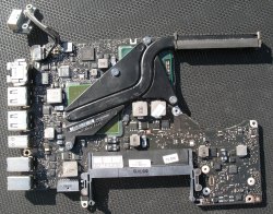
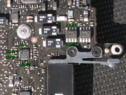
Hi,still no luck.Removed the LTBDM chip & still got ground on pad 6 on motherboard..The data sheet for the LTBDM says pin 4 ground.I even replaced LTBDM & the diode marked A1,put the 47 ohm resistor & inductor back on & the resistor burns up again.Thanks again for all your replies,your a great person for trying to help out a newbie like me.Hope your enjoying your retirement.CheersFirst off, I just noticed that LT3470-ETS8 on the A1286 DOES NOT have the same pinout as the LT3470-A in A1287, so my explanation is based on the A1287 alone.
Measuring on "pin2 pad" of L6995 is the "load" side of the power supply. If you see a much lower resistance here, lift off pin2 (BIAS pin) of the LTBDM chip to further isolate the LTBDM from the load side (this is the BIAS input to the chip so that it can maintain the "3.425v output".
If you get around 13 Ohms or more, then the LTBDM is most likely shorted internally. I assumed that when you are measuring these shorts, the LTBDM have not been removed from the board? According to the chip spec, pin4 (SW pin) output voltage is set by the formula: Vout = 1.25 x (1+ R1/R2). Pin1 is the FB line of this chip, and should not be zero/ground. The fact that you've got ground on pin6 (again based on 1A1287), points to a bad LTBDM chip. If you remove this chip altogether and measure pin4, 6 and 8 pads, they should be open circuit to ground. My guess: after removing the chip and installing a new 47 Ohm resistor, that 47 Ohm should be fine when the adapter or battery is connected.
Got a tip for us?
Let us know
Become a MacRumors Supporter for $50/year with no ads, ability to filter front page stories, and private forums.
SMC Issue on MBP 13 - Hardware Troubleshooting Guide
- Thread starter Dadioh
- Start date
- Sort by reaction score
You are using an out of date browser. It may not display this or other websites correctly.
You should upgrade or use an alternative browser.
You should upgrade or use an alternative browser.
Hi,still no luck.Removed the LTBDM chip & still got ground on pad 6 on motherboard..The data sheet for the LTBDM says pin 4 ground.I even replaced LTBDM & the diode marked A1,put the 47 ohm resistor & inductor back on & the resistor burns up again.Thanks again for all your replies,your a great person for trying to help out a newbie like me.Hope your enjoying your retirement.Cheers
Based on your description (pin4=ground), you are really refering to the LT3470-ETS8 chip (in MBP A1286) which has a different pin-out than the LT3470-A chip (in MBP A1287). So, we need to be "synced-up" on which MBP model, schematic and chip we are talking about. For some unknown reason to me, why Linear Technology would package the same IC in different pin out configuration is mind-boggling. See the attached PDF file and notice what pin4 represent on the different packages.
Measuring/Seeing ground on PAD6 is bad news regardless of which chip it is, i.e., in ETS8 pin6 = boost signal, in -A chip pin6 = Vcc (chip power). This would indeed burn up the 47 Ohm resistor with/without the LTBDM soldered in. Are you sure you are using the correct LTDBM chip that match the logicboard? Putting an ETS8 package on a logic board that expect -A version would cause that resistor to burn and vice versa.
If I were you, I'd put the resistor and diode and leave out the LTBDM and see if the resistor then burned up when powered. If it does, you have a short in the logicboard. You are out of luck for sure.
If it DOES NOT, then check PAD3 and PAD6. If PAD3 has the same voltage as the diode cathode (and PAD6 should read 0 volt), you need the LT3470ETS8 chip. If PAD6 is the one that neasured the same voltage as the diode (and PAD3 should read 0 volt), then you need the LT3470-A chip. They are NOT interchangeable.
----------
See the attached PDF file and notice what pin4 represent on the different packages.
Forgot to attach the file. here it is.
Hello,It is the LT3470ETS-8,it does show a couple different versions,but I think there be different numbers on top & a bit different chip package.Based on your description (pin4=ground), you are really refering to the LT3470-ETS8 chip (in MBP A1286) which has a different pin-out than the LT3470-A chip (in MBP A1287). So, we need to be "synced-up" on which MBP model, schematic and chip we are talking about. For some unknown reason to me, why Linear Technology would package the same IC in different pin out configuration is mind-boggling. See the attached PDF file and notice what pin4 represent on the different packages.
Measuring/Seeing ground on PAD6 is bad news regardless of which chip it is, i.e., in ETS8 pin6 = boost signal, in -A chip pin6 = Vcc (chip power). This would indeed burn up the 47 Ohm resistor with/without the LTBDM soldered in. Are you sure you are using the correct LTDBM chip that match the logicboard? Putting an ETS8 package on a logic board that expect -A version would cause that resistor to burn and vice versa.
If I were you, I'd put the resistor and diode and leave out the LTBDM and see if the resistor then burned up when powered. If it does, you have a short in the logicboard. You are out of luck for sure.
If it DOES NOT, then check PAD3 and PAD6. If PAD3 has the same voltage as the diode cathode (and PAD6 should read 0 volt), you need the LT3470ETS8 chip. If PAD6 is the one that neasured the same voltage as the diode (and PAD3 should read 0 volt), then you need the LT3470-A chip. They are NOT interchangeable.
----------
Forgot to attach the file. here it is.
Pin 6 is the boost & should have 3.42 v.The schematic shows 3.42 volts on pins 5,6 & 8.I checked another board & it had the 3.42 volts on pin 6 but that board don't work on ac power.
I find it strange that I got three boards here acting the same & burning up the 47 ohm resistor.They all had pads 6 & 8 shorted.Removed inductor L6995 & it took short off pad 8 but still got short on pad 6.
I gotta find some 47 ohm resistors & try what you mentioned.
Thanks
short of 3.42v voltage
Hello,
I just have a A1287 MB 2010 where the 3.42v power rail just shows about 1.7v which leads to a short somewhere on the board. I already desoldered the lt3470a and it's still the same. Then I started to look what is connected to this power rail and desoldered many components one by one. Now only the smc, the OPA OPV, two Multi-Gates and the connection to the vbat input pin of the mcp97 is left. I would now go for the smc and try to desolder it.
Before I go on I wanted to ask you if any of you came such far with a similare problem? Can I replace the smc easily by another one (does the smc gets its programming from an internal rom or external flash, I couldn't find out yet). Where can I find the OPA OPV and the Multi-Gates located on the PCB?
Would be nice if anyone could help!
Many thanks,
Mario
Before removing the SMC, I have a few questions:
1. What is the voltage level at anodes of the two diodes where the DCIN power and the battery power are OR'ed together after the LT3470A was removed? You should see the 16.5V (or 18.5v) from the magsafe adapter on one anode, and 10v-13v battery power on the other anode. Only one of these is needed to generate the 3.42v rail.
2. If the voltages are not correct/low, the 3.42v may not be available. The voltages could be low because of many reasons, for example the magsafe is not providing power, or the MOSFETs that that normally provide charging current to the battery is shorted.
3. I believe the SMC and the Battery Charging IC are custom parts for Apple. You will not be able to buy it off the shelf new, unless someone is selling that as "pulls" from another logic board. I also doubt that the SMC is bad as I believe the 3.42v rail is only lightly related to SMC control.
Hi all, i'm here again (damn) with a problem, my repaired mbp has a problem that i didn't noticed before.. when i close the lid, it doesn't go to sleep...
What i've already tried:
Pram reset, repair hdd permission
No luck..
What i have to try next:
SMC reset (here i can't plug power adaptor)
Format disk and reinstall OS..
IF neither that works what i have to do?
damn.. i have just find a buyer, and only now noticed that issue.. fortunately i have to give it tomorrow..
@crmdata: how do you come back to life your dead mpb after DCin board change?
http://www.ifixit.com/Guide/MacBook-Pro-13-Inch-Unibody-Mid-2010-Logic-Board-Replacement/4314/5
See step 15, that is also the sleep sensor. It's possible the repair person tore the cable (very easy to do, under the battery) or it's stuck under the logic board or just loose.
You can also check to see if it's plugged in by pressing the battery level button on the side. If it does not have any activity, it's not plugged in or torn.
I know this does not belong here, but having read the posts above, if there is anyone who is going to be able to resolve this issue, or at least point me in the right direction, it is certainly going to be you.
Machine : White MB 1181
Issue : battery 'Not charging'
* Reported Battery condition: 'Normal'
* Powers up with remaining battery charge: Yes (29% remaining)
* Reset SMC : No change
* Water damage: No
* Temporary SMC bypass boots machine: Yes
* System Profiler reports battery is connected and functioning normally
* System profiler reports that AC adapter is connected but outputting 0 watts and cannot determine type. (even though temp SMC bypass w/no battery boots machine)
* AC Adapter has ever so slight green light.
Is by beloved mac cactus? There is a local laptop repair shop who i could take it to, but i thought i would check with you scholarly gentlemen (and women as appropriate) first. Once again, sorry for hijacking (and this being my first post)
I can post any relevant screenshots if required, with the remaining charge that is in the battery
Cheers,
Aaron
http://www.ifixit.com/Guide/MacBook-Pro-13-Inch-Unibody-Mid-2010-Logic-Board-Replacement/4314/5
See step 15, that is also the sleep sensor. It's possible the repair person tore the cable (very easy to do, under the battery) or it's stuck under the logic board or just loose.
You can also check to see if it's plugged in by pressing the battery level button on the side. If it does not have any activity, it's not plugged in or torn.
Hi, the battery level leds works fine, just reset SMC and no change (if i correctly reseted the smc.. the data and hours will be reseted to?)
Tonigh i'll try to open and see...
Hi all, i'm here again (damn) with a problem, my repaired mbp has a problem that i didn't noticed before.. when i close the lid, it doesn't go to sleep...
What i've already tried:
Pram reset, repair hdd permission
No luck..
What i have to try next:
SMC reset (here i can't plug power adaptor)
Format disk and reinstall OS..
IF neither that works what i have to do?
damn.. i have just find a buyer, and only now noticed that issue.. fortunately i have to give it tomorrow..
@crmdata: how do you come back to life your dead mpb after DCin board change?
After the DCIN board replacement,a s bizzle mentioned I broke
the thin ribbon cable that connects the sleep sensor/battery indicator. Got one from eBay for about 15 USD and after a long boot with black screen it finally came back to life. Check the cable near the right side of the Mac. If you're lucky it could be just that it was not plugged in.
----------
I know this does not belong here, but having read the posts above, if there is anyone who is going to be able to resolve this issue, or at least point me in the right direction, it is certainly going to be you.
Machine : White MB 1181
Issue : battery 'Not charging'
* Reported Battery condition: 'Normal'
* Powers up with remaining battery charge: Yes (29% remaining)
* Reset SMC : No change
* Water damage: No
* Temporary SMC bypass boots machine: Yes
* System Profiler reports battery is connected and functioning normally
* System profiler reports that AC adapter is connected but outputting 0 watts and cannot determine type. (even though temp SMC bypass w/no battery boots machine)
* AC Adapter has ever so slight green light.
Is by beloved mac cactus? There is a local laptop repair shop who i could take it to, but i thought i would check with you scholarly gentlemen (and women as appropriate) first. Once again, sorry for hijacking (and this being my first post)
I can post any relevant screenshots if required, with the remaining charge that is in the battery
Cheers,
Aaron
First thing to try isa known good MagSafe adapter (borrow from a friend).
Next, borrow hie/her battery and try it with your charger, then your friend's.
From the symptoms you provided, the SMC is able to communicate with the DCIN board and perhaps the adapter, but the adapter is not supplying the neccessary current flow to power/charge the battery.
After the DCIN board replacement,a s bizzle mentioned I broke
the thin ribbon cable that connects the sleep sensor/battery indicator. Got one from eBay for about 15 USD and after a long boot with black screen it finally came back to life. Check the cable near the right side of the Mac. If you're lucky it could be just that it was not plugged in.
Dear.. i think we are linked in some kind..
firts: this is what i done to my sleep sense:

and then.. the Superdrive don't work.. it don't grab completely the CDs and then eject it.
🙁
SO, now the mpb that i have to sell tomorrow have a new sleep board and a working superdrive.. and my personal mbp not...
how much u spent for you superdrive?
Really.. i can't understand why there is so much confusion about this dammit superdrive code...
661-5082, 661-4737, 661-5165, 661-4736, 661-4737, 678-1452D, AD-5960S, uj868 uj-868, GS23N, GS22N, GS21N
possible that all of these code are compatible with my Mbp? assuming that many of them correspond to a single component ..
Last edited:
Dear.. i think we are linked in some kind..
firts: this is what i done to my sleep sense:[url=http://img268.imageshack.us/img268/870/p1030003a.th.jpg]Image[/URL]
and then.. the Superdrive don't work.. it don't grab completely the CDs and then eject it.
🙁
SO, now the mpb that i have to sell tomorrow have a new sleep board and a working superdrive.. and my personal mbp not...
how much u spent for you superdrive?
Really.. i can't understand why there is so much confusion about this dammit superdrive code...
661-5082, 661-4737, 661-5165, 661-4736, 661-4737, 678-1452D, AD-5960S, uj868 uj-868, GS23N, GS21N, GS21N
possible that all of these code are compatible with my Mbp? assuming that many of them correspond to a single component ..
That little notch looked like it was a pinch ribbon cable that was then cut thru by the battery retaining screw. This was what happened to Daddioh a while back. Mine was actually ripped thru. I paid around 45USD for my Superdrive and I made sure I got the same exact part number.
Before removing the SMC, I have a few questions:
1. What is the voltage level at anodes of the two diodes where the DCIN power and the battery power are OR'ed together after the LT3470A was removed? You should see the 16.5V (or 18.5v) from the magsafe adapter on one anode, and 10v-13v battery power on the other anode. Only one of these is needed to generate the 3.42v rail.
2. If the voltages are not correct/low, the 3.42v may not be available. The voltages could be low because of many reasons, for example the magsafe is not providing power, or the MOSFETs that that normally provide charging current to the battery is shorted.
3. I believe the SMC and the Battery Charging IC are custom parts for Apple. You will not be able to buy it off the shelf new, unless someone is selling that as "pulls" from another logic board. I also doubt that the SMC is bad as I believe the 3.42v rail is only lightly related to SMC control.
Many thanks cmdrdata for your help!!
The reasone why I am thinking there is a short on the 3v42 somewhere is that I measure about 5ohms against GND there and this is too low. On the anode side from the magsafe there is the voltage (I don't remember the correct value but > 16v). I already desoldered all components except the passive ones and except the ball VBAT on the MCP97 which are powered by the 3v42 rail but no change of the resistance against GND.
And additionally I think I did something wrong. I tried to connect an external 3v42 source to analyze there the the most heat on the board comes from but the only component which heated up was the CPU which is quite odd because it is not connected to that rail. I can just assume any backpowering somewhere but I am not sure about it and haven't located it yet. Anyway this was apparently a big mistake becasue now the resistance between the 3v42 rail and GND is about 2 ohms.
In the end my assumption is that the PCB is faulty anyhow pressumably a short of two layers somewhere caused by a fluid spill.
It seems that I can dump the board if nobody has a bright idea what else I could do about it.
Many thanks again for the SMC details!
Best wishes to all!!
Last edited:
Dead 2008 MacBook 2.0GHz - Liquid Damage
This thread has been very educational.
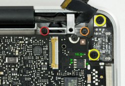
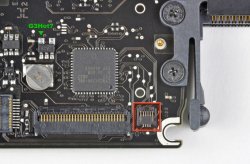
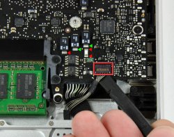
I am trying to resurrect a dead MacBook which suffered some liquid damage and I'm looking for a little advice. The symptoms are totally dead notebook. No power, nothing - only a flashing green light on the magsafe connector. I cleaned the corrosion from all the parts I could see and put it back together but no change. I think the DC-in board is working because I can get 16.5 volts on various points on the logic board (see green arrows on 1st image). Please ignore the circled items, I swiped the images from iFixit. I can also get voltage on the fuse near the DC-in but I can't seem to get voltage on the fuse near the battery connector (however, I have verified the fuse is not blown). What should I try before I give up and bake the thing in the oven to try a reflow? - not real fond of that option.
Also, I am not sure where the G3Hot is on my model of logic board. Is it the pad identified in the 2nd picture?
Thanks in advance.
Mike
Attachments
This thread has been very educational.
I am trying to resurrect a dead MacBook which suffered some liquid damage and I'm looking for a little advice. The symptoms are totally dead notebook. No power, nothing - only a flashing green light on the magsafe connector. I cleaned the corrosion from all the parts I could see and put it back together but no change. I think the DC-in board is working because I can get 16.5 volts on various points on the logic board (see green arrows on 1st image). Please ignore the circled items, I swiped the images from iFixit. I can also get voltage on the fuse near the DC-in but I can't seem to get voltage on the fuse near the battery connector (however, I have verified the fuse is not blown). What should I try before I give up and bake the thing in the oven to try a reflow? - not real fond of that option.
Also, I am not sure where the G3Hot is on my model of logic board. Is it the pad identified in the 2nd picture?
Thanks in advance.
Mike
Hi Mike,
I don't think reflow is a solution for you. Reflow is typically related to bad solder joints and particularly bad BGA solder joints (CPU and Northbridge).
Not sure about the G3Hot location you showed but it looks to be about the same spot as the Macbook Pro location. Do you measured a little over 3V on that pin?
Your DC in is fine if you are getting 16.5V around the board. Odd that you do not get at least 12V on the fuse by the battery connector. On a non-charging Macbook (fairly common) the battery charging circuit is not boosting the 12V to the charging voltage but it is odd that it is zero. Check around the battery charging circuit and see if there is any obvious liquid damage.
The charger is a 28 pin QFN part number ISL6258. Going from memory it is due north of the right dimm module edge (no pun intended).
I agree with you on the reflow. I'm not going to do it. I have just heard other people say it fixed water damage sometimes and I was starting to feel desparate.
I am worried I do have the correct G3Hot location because I am not getting much there. I get about 1v which I think is the PRAM battery because I get that same voltage when no power source is connected!
Yeah, 0v on the battery fuse. Very strange. There is no obvious liquid damage that I can see but I can't find the part you describe. My model number is MB466LL/A. It is an aluminum unibody model with stacked dimms. Is that part number good for my model?
Thanks for your help.
Mike
I found some voltage NEAR the fuse but not on it. The green arrows point to areas where I found 16.5v. The red arrows have no voltage.
Mike
The positive side of any of the electrolytic caps is a good place to check for voltages. On a running system they should ALL have voltage on them by definition.
The QFN package straight north of the mounting screws on the DIMM is the charging circuit IC by the way. That is where your focus should be in troubleshooting the battery charging issue. The fuse that you indicated zero volts on is the main fuse for the board post charging circuit. If it is zero then the charging circuit has something seriously wrong with it. The two 8 pin FET packages right beside the DIMM package should be checked for voltage. They are the inrush FETS for the battery. If they are zero volts work backwards from there.
I found some voltage NEAR the fuse but not on it. The green arrows point to areas where I found 16.5v. The red arrows have no voltage.
Mike
The fuse near the battery connector is the system power fuse for the 12VDC that powers the entire MacBook when it is turned on. This 12V (nominal) can be sourced from the DCIN (magsafe) and/or BATT. Since the problem is due to water damage, I suspect that one or more component in the charging and power arbitration logic is damaged. As daddioh mentioned look at the voltages at the pair of MOSFETs that boost the ISL6258 chip. These MOSFETs received signal from IC pin 24 and 22 (charger_ugate and charger_lgate). The ugate and lgate signals go to the DCIN MOSFETs. They regulate and allow DCIN voltage to 12v and then flow to the system and also charge the battery.
Last edited:
Wow, I can't thank you both enough for your efforts to help me. This thread is really incredible.
Unfortunately, there is no voltage on either of those FETs. Does that mean the ISL6258 is bad/shorted or do I need to check the DC-in FETs?
I'll be honest, I'm swimming in pretty deep water here but I am learning a lot and it is fun.
Thanks again.
Mike
Unfortunately, there is no voltage on either of those FETs. Does that mean the ISL6258 is bad/shorted or do I need to check the DC-in FETs?
I'll be honest, I'm swimming in pretty deep water here but I am learning a lot and it is fun.
Thanks again.
Mike
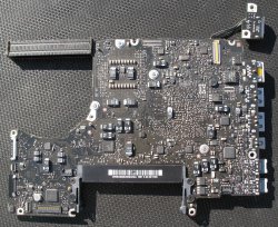
I took some hi-res pictures in direct sun light that really show the condition of the board and layout of components. I did remove the heat sink when I looked for corrosion and cleaned the board but I put it back on when I thought I was going to fire it back up. Unfortunately, that never happened. 🙁
Where are the DC-in FETs located?
Mike
Where are the DC-in FETs located?
Mike
Attachments
Pin 12 of the ISL6258 SHOULD have 3.42v (the always on G3HOT source). If this not there, then your first effort should be to restore this 3.42v source. If G3HOT is OK, then one of the MOSFET (the one driven by ugate signal) should have the S (Source) pin 5 to have 16.5v from the magsafe supply (see next paragraph). The MOSFET driven by the lgate signal should have the D (Drain) pins1,2,and 3 connected to ground.Wow, I can't thank you both enough for your efforts to help me. This thread is really incredible.
Unfortunately, there is no voltage on either of those FETs. Does that mean the ISL6258 is bad/shorted or do I need to check the DC-in FETs?
I'll be honest, I'm swimming in pretty deep water here but I am learning a lot and it is fun.
Thanks again.
Mike
If you don't have the 16.5v at the ugate MOSFET, then there are another pair of MOSFET near the DCIN board that function as an "in-rush" and "reverse-current" protection. These MOSFETs or its gate signal may prevent the 16.5v from coming thru to the charger circuit.
In the hopes of generating some technical sharing on this particular HW issue I am starting up a thread to share the symptoms and potential solution to what appears to be a fairly common failure mode on the Macbook Pro 13" (and possible other unibody Macbooks). I suspect these are usually the result of some trauma or liquid spill that damages some aspect of the SMC control circuit. Please feel free to add your own experiences/symptoms and hopefully we can get close to the HW solution.
The symptoms:
The MBP will appear to be completely dead. No response to power button. No response to standard SMC reset procedure.
Temporary bypass:
With the magsafe disconnected press and hold the power button. While continuing to hold the power button plug in the magsafe connector. Continue to hold down the power button for 5 to 10 seconds. Release the power button and wait a couple of seconds. Now press and release power button. PRESTO! The Macbook chimes and starts up but with fan on high speed. Boots up into OSX but with a few caveats which I list below:
Fan runs on high speed.
iStat menus can not sense either temperature or fan speed so access to those sensors is not there. Probably why the fans run on high.
No voltages or power displayed by iStat
"About this Mac" can not see the battery even though it is plugged in.
Does not charge the battery.
Everything else seems to work (Airport, USB, iSight, DVD, Disk)
Taken from the Apple support page about resetting the SMC suggests all of these symptoms are related to non-communication with the SMC. Not sure at the moment why the plugging in of the magsafe while holding the power allows the system to boot. Maybe bypasses some sort of SMC check?
The System Management Controller (SMC) is responsible for many low-level functions on Intel-based Macs. These functions include:
Responding to presses of the power button
Responding to display lid opening and closing on portable Macs
Battery management
Thermal management
The SMS (Sudden Motion Sensor)
Ambient light sensing
Keyboard backlighting
Status Indicator Light (SIL) management
Battery status indicator lights
Selecting an external (instead of internal) video source for some iMac displays
Do you have the battery connected or disconnected when you do this?
OK, I think I have it now but just to make sure, I have attached an image. Do I have the pins correct? I don't want to go probing the wrong pins! 😱Pin 12 of the ISL6258 SHOULD have 3.42v (the always on G3HOT source). If this not there, then your first effort should be to restore this 3.42v source. If G3HOT is OK, then one of the MOSFET (the one driven by ugate signal) should have the S (Source) pin 5 to have 16.5v from the magsafe supply (see next paragraph). The MOSFET driven by the lgate signal should have the D (Drain) pins1,2,and 3 connected to ground.
If you don't have the 16.5v at the ugate MOSFET, then there are another pair of MOSFET near the DCIN board that function as an "in-rush" and "reverse-current" protection. These MOSFETs or its gate signal may prevent the 16.5v from coming thru to the charger circuit.
Mike
Attachments
OK, I think I have it now but just to make sure, I have attached an image. Do I have the pins correct? I don't want to go probing the wrong pins! 😱
Mike
Looks right.
----------
Do you have the battery connected or disconnected when you do this?
Disconnected.
Register on MacRumors! This sidebar will go away, and you'll see fewer ads.


