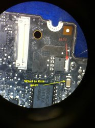
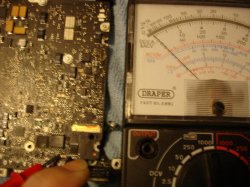
The line voltage (magsafe power) is routed through the 47 Ohm resistor and "OR-ed" with battery power (the ntwo DIODE thing) to ALWAYS generate G3HOT low current signal. This G3HOT is 3.42v, an output from a voltage regulator chip made by Linear Technology p/n LT34570A. This output is only to provide power to the SMC so it can respond to various power control stimulus. According to the schematic, it is only designed to supply 3.425v at 250mA max. So if G3HOT is correct, the SMC and other critical components powered by G3HOT for example with the battery connected, when it sees a magsafe connected will then communicate with the adapter and if all is well turn on the 16.5v by enabling the inrush and reverse current MOSFETs. Recall I mentioned in previous post that the magsafe only output the 16.5v if it sees a low impedance load. Well, turning on the two MOSFETs is equivalent to loading the magsafe line because on the other side of the MOSFET is input to the 12V system bus power regulator that supply power to the system board functions. If you follow the raw DC in line, it goes to another pair of MOSFETs that is controlled by the IC made by Intersil, ISL 6278A. This chip also control the battery charger (yet another MOSFET). The MOSFET regulates the charging current to the battery. Of course the SMC also control the turning on of the logic board by sensing other inputs like power on switch, other voltage regulators output, SODIMM and other stuff. So the SMC can prevent power up if any of the sensing items it monitors are not up to par.
About battery power only: it seemed that 12v bus (AC or BATT, or BOTH sourced) is the main supply that in the end powers everything else in the system. If the system only works with AC, then BATT power and charging which is gated by MOSFET Q7055 or (Q7056 in 15" model) is not allowing juice to flow. On the other hand, if it works with BATT but not AC, then the MOSFETs I described earlier are the gates that disable AC power from gating it to the 12v bus.


