I think OpenBoardView should be able to read the CAD files, but I've been using FlexBV which I know works with them (though they take awhile to load).Thank you very much!
... apologies for dumb questions but:
ive been using board view with no issue as most of the files im opening are in*.bvr file format. however this one is in a *.cad file format. my MacBook (m1pro) is struggling to read this using 'openboardview' from GitHub. most of the places ive read up on said it should be able to read it since the 2022 update but im having no joy.
any info would be appreciated. thanks
Got a tip for us?
Let us know
Become a MacRumors Supporter for $50/year with no ads, ability to filter front page stories, and private forums.
Apple Silicon Soldered SSD Upgrade Thread
- Thread starter dosdude1
- WikiPost WikiPost
- Start date
-
- Tags
- apple silicon nand upgrade
- Sort by reaction score
You are using an out of date browser. It may not display this or other websites correctly.
You should upgrade or use an alternative browser.
You should upgrade or use an alternative browser.
- Status
- The first post of this thread is a WikiPost and can be edited by anyone with the appropiate permissions. Your edits will be public.
I tried 2 chips and had the same error.1x 1TB is not a valid config, so that will never work. If you tried to restore that way, that chip has been improperly programmed and now can no longer be used.
We have P15 nand programmer. But it cannot recognize h23b8t85k7afj-bc for now. Is there a way to make this chip blank again?
Could you please recommend a program that includes an up-to-date schematic of the board and allows viewing a valid configuration for the iPad Pro M1?
where to dig for NAND: DBL_PRIME BOM OPTION?
Last edited:
Thank you Collin! much appreciated!I think OpenBoardView should be able to read the CAD files, but I've been using FlexBV which I know works with them (though they take awhile to load).
Last edited:
once a nand has been written upon, there is no going back to blank....and in that case the nand is most likely unusableI tried 2 chips and had the same error.
We have P15 nand programmer. But it cannot recognize h23b8t85k7afj-bc for now. Is there a way to make this chip blank again?
Could you please recommend a program that includes an up-to-date schematic of the board and allows viewing a valid configuration for the iPad Pro M1?
where to dig for NAND: DBL_PRIME BOM OPTION?
unless you have the exact dump files needed for that specific chip model n installation config. I only have the dump files for KICM223 Nands. (which is a BGA110 chip-1tb x2 config used in m1 series)
but this adds another layer of potential issues as by using dump files you have now assigned each nand to a particular slot/landing pad on the board itself (un000 or un100) often seen on the videos listen as 0 and 1. so one must ensure that they solder each of the nands in its designated location.
these and a host of other issues is why most people resort to ensuring the nand chips they are using are in fact blank
Last edited:
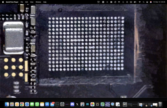
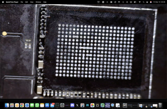
ermm so I scrubbed using a little bit too much pressure.... been used to doing BGA110 and they are a little more durable than these 315's.... have anyone else had this kinda issue? any suggestions?
I don't have a schematic for this exact board but ive seen the pin lay out on other 315 and noticed a few of them are identical pins (two pins right next to each other and connect to the exact same point on board view). but truth be told I don't know the extent of this kinda damage.
just want to know if it is even worth going round and adding the thinnest possible layer of UV mask to differentiate each pad?
they all seem to be present... no ripped pads, just damaged lol
any info would be useful. much appreciated!
Attachments
Nothing to worry about, those pins are supposed to be connected so it won't hurt anything. Though, one thing I do notice is the ends of the components on the one side seem to have a bit of their solder removed (this can happen if you scrape too close to them with the underfill tool). I'd recommend going over them and touching each one up. Leaving them that way could cause issues (I have had it happen before).ermm so I scrubbed using a little bit too much pressure.... been used to doing BGA110 and they are a little more durable than these 315's.... have anyone else had this kinda issue? any suggestions?
I don't have a schematic for this exact board but ive seen the pin lay out on other 315 and noticed a few of them are identical pins (two pins right next to each other and connect to the exact same point on board view). but truth be told I don't know the extent of this kinda damage.
just want to know if it is even worth going round and adding the thinnest possible layer of UV mask to differentiate each pad?
they all seem to be present... no ripped pads, just damaged lol
any info would be useful. much appreciated!
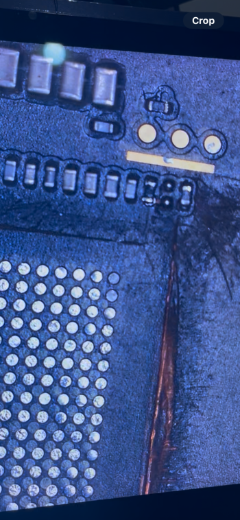
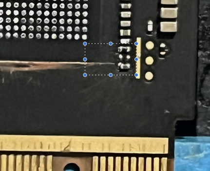
I tired to follow your (Dosdude1) instructions and touch up the edges, all was going fine and well until absolute disaster struck... was holding the tweezers with THAT missing piece and needed to sneeze, was at the worst possible timing.
now i've got a headache of a situation from a simple upgrade as the tiny component went flying and trying to find it feels impossible. genuinely gutted, such a simple error. beaten my self up about it plenty and now came on here to seek help
so this all happened when I was doing a Mac mini m4 and in a nutshell I lost the 2nd to last piece on the end of this row. if anyone can help me locate find the values of this component and then maybe I could find a replacement on mouser.... finger crossed.
any advice im all ears...
Attachments
Closest to the connector in that spot should be a 0 ohm resistor, above that a 10pF 25V capacitor, and above that a 200 ohm resistor. It looks like the capacitor may have gotten moved down to the wrong set of pads.I tired to follow your (Dosdude1) instructions and touch up the edges, all was going fine and well until absolute disaster struck... was holding the tweezers with THAT missing piece and needed to sneeze, was at the worst possible timing.
now i've got a headache of a situation from a simple upgrade as the tiny component went flying and trying to find it feels impossible. genuinely gutted, such a simple error. beaten my self up about it plenty and now came on here to seek help
so this all happened when I was doing a Mac mini m4 and in a nutshell I lost the 2nd to last piece on the end of this row. if anyone can help me locate find the values of this component and then maybe I could find a replacement on mouser.... finger crossed.
any advice im all ears...
If you want to order all the parts, my Mouser project can be found here: https://www.mouser.com/ProjectManager/ProjectDetail.aspx?AccessID=fd9bd9decb
Otherwise, these are the parts you need:
- 10pF capacitor: https://www.mouser.com/ProductDetail/81-GRT0335C1E100JA2D
- 200 Ohm resistor: https://www.mouser.com/ProductDetail/667-ERA-1AEB201C
- 0 Ohm resistor:https://www.mouser.com/ProductDetail/667-ERJ-1GN0R00C
Last edited:
that worked out great as I had a donor board with missing component that I can use.... but only for me realize that I have messed up with the other part of the board with more passive components.(as you can see in my last post) silly one to over look, I know!
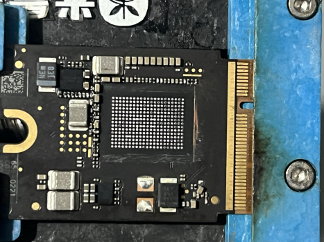
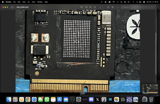
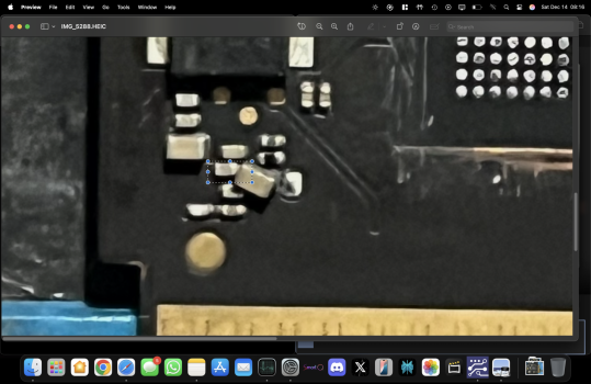
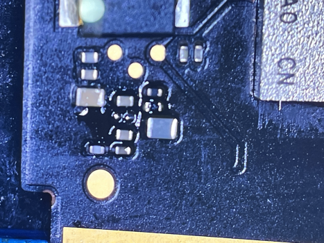
could I bug you for a read on just one more part for me. the one highlighted in the pictures below. the larger on is fine. thats been put back but the smaller one ive got mixed up with.... thanks again!
added an updated pic to show what is missing.
could I bug you for a read on just one more part for me. the one highlighted in the pictures below. the larger on is fine. thats been put back but the smaller one ive got mixed up with.... thanks again!
added an updated pic to show what is missing.
Attachments
Last edited:
Looks like just a decoupling capacitor, which can be left omitted.that worked out great as I had a donor board with missing component that I can use.... but only for me realize that I have messed up with the other part of the board with more passive components.(as you can see in my last post) silly one to over look, I know!
could I bug you for a read on just one more part for me. the one highlighted in the pictures below. the larger on is fine. thats been put back but the smaller one ive got mixed up with.... thanks again!
added an updated pic to show what is missing.
Hi.... hope you are all enjoying your xmas breaks! just a quick one.Here you go. You need to stuff BOM options "SSD_OC1VR1" and "SSD_8L" to use all 8 NANDs. Yes, USB-C port closest to the MagSafe port is the port used for DFU restore.
upon installing all the components as you mentioned when searching the schematic for "SSD_OC1VR1" and "SSD_8L" in the corresponding locations, including populating all 8 pads... is there a step in-between or straight into dfu and restore?
also how can I identify the 'decoupling' components that are not needed for 100% full functionality?
cheers!
Last edited:
Decoupling components are all capacitors, with one pin connected to ground and the other to a power supply rail. Their function is to reduce noise on power supply voltages for components located near the decoupling caps (in this case, one of the SSD NANDs).
Designers frequently provide more decoupling than is absolutely requried to get the system to work, which is why you can usually get away with leaving one out. Do not make a habit of this, though, and it is best to limit this to cases where there are many decoupling caps for a particular power supply rail, meaning that removing just one does not greatly reduce the amount of decoupling for that rail.
You can definitely get a circuit to work without all its decoupling caps, but if you are too aggressive you may make the system unreliable, possibly in subtle ways that aren't immediately obvious. Thus, my recommendation to limit yourself to at most one or two, and only if there are many.
You may see multiple decoupling capacitor values attached to a single power supply rail. An individual capacitor's capacitance and ESR (equivalent series resistance) ratings influence which frequency bands the decoupling cap is best at filtering. If the circuit designer used multiple cap values, that's usually because they wanted to cover more of the noise frequency spectrum. Make sure that you aren't aren't eliminating the only instance of a particular capacitance value.
Thank you for your response. If I order 2 KICM223 chips of 1TB each, is there a chance that everything will work? At the very least, will it be possible to reset them to a clean state? And theoretically, should it work on an iPad Pro with the M1 chip?once a nand has been written upon, there is no going back to blank....and in that case the nand is most likely unusable
unless you have the exact dump files needed for that specific chip model n installation config. I only have the dump files for KICM223 Nands. (which is a BGA110 chip-1tb x2 config used in m1 series)
but this adds another layer of potential issues as by using dump files you have now assigned each nand to a particular slot/landing pad on the board itself (un000 or un100) often seen on the videos listen as 0 and 1. so one must ensure that they solder each of the nands in its designated location.
these and a host of other issues is why most people resort to ensuring the nand chips they are using are in fact blank
2 blank KICM223 NANDs will work fine on the M1 iPad Pro. You just have to make sure you install all the passive components for the second NAND if yours originally only had a single NAND.Thank you for your response. If I order 2 KICM223 chips of 1TB each, is there a chance that everything will work? At the very least, will it be possible to reset them to a clean state? And theoretically, should it work on an iPad Pro with the M1 chip?
Hi, I am looking to upgrade my mac mini M4 base model storage, is "K6B2" 1TB the only IC chip compatible for this upgrade?
Chinese sellers are offering alternative IC models and I am unsure if they would work.
- 3T3D-1TB <<< seller recommends this one...but never heard of it.
- SDSFGKLKH-1T
Chinese sellers are offering alternative IC models and I am unsure if they would work.
- 3T3D-1TB <<< seller recommends this one...but never heard of it.
- SDSFGKLKH-1T
be very carful when doing this upgrade as there is a slight size difference in the chips. The break away ssd board is designed to be compatible with these nands you have mentioned, even thought the stock ones do look slimmer.Hi, I am looking to upgrade my mac mini M4 base model storage, is "K6B2" 1TB the only IC chip compatible for this upgrade?
Chinese sellers are offering alternative IC models and I am unsure if they would work.
- 3T3D-1TB <<< seller recommends this one...but never heard of it.
- SDSFGKLKH-1T
one must ensure you don't mess with any of the passive components around as this can be a source of many more problems.... I mention this as you will need to remove/clean the old black under-fill that is used to hold the smaller nand in place, obviously you are going to be working with hot air/soldering iron very close to them. so a word of warning after removing the old Nand be very very very carful when preping the nand pads as this is a critical part in which things can go wrong in an instant.
all the best mate!
M3 Max 16” MacBook Pro upgrade from 512GB to 8TB SUCCESSFUL with 8x K5A8 NANDs after installing over 100 passive components (plus some voltage regulators)! Because there are no schematics available for this model, I referenced an M2 Pro 16” MacBook Pro schematic to painstakingly draw a set of diagrams to locate each of the necessary components on the M3 Max board (as all the components are identical between the two, the locations on the board, though, are not). I should note that I only installed the necessary components, and omitted a number of decoupling capacitors, which has proven to not be an issue. Installing those would bring the component total to almost 200... Which is a lot to solder by hand.
Relevant Mouser projects and parts:
- Mac NAND LP, one project order needed per added NAND: https://www.mouser.com/ProjectManager/ProjectDetail.aspx?AccessID=fd9bd9decb
- Mac NAND Power, all components needed to populate NAND1 power circuit on M2 and later, minus voltage regulator ICs: https://www.mouser.com/ProjectManager/ProjectDetail.aspx?AccessID=5633742c1f
- Mac NAND SSD1 Additions, some additional support components for second set of NANDs: https://www.mouser.com/ProjectManager/ProjectDetail.aspx?AccessID=0abaa47822
- 338S00600 voltage regulator: https://www.aliexpress.us/item/3256806668172757.html
- LT8642EV-1 voltage regulator: https://www.aliexpress.us/item/3256805855879468.html
View attachment 2458598View attachment 2458599View attachment 2458600View attachment 2458601
so I m in the process of giving this a go with an 16 inch m2 machine which came with 1TB (4 landing pads used).
so I started populating the components and all is going well but I really didn't expect it to be this much work... certainly not easy and not for the faint hearted! I really appreciated the sharing of your projects as that has enabled someone like me to carry out this kind of task.
so couple of things I unsure about:
1)what component from your mouser project list are you using to populate;
CN846 - 0.1uf, 10%, 6.3V CERM-X5R 0201
2) this kinda upgrade requires one to be extremely meticulous and its my 1st time so any h help would be useful.
so when I see the schematic mention 'mirror with' like this 'MIRROR_WITH=CN930' if I populate one, then I don’t need to install the other the mirroring one….or do I need to install components to both sides of the mirrored pads?
3) when I see there is usually 3 values on the schematic for each passive component to be installed and the mouser project doesn't have an exact item match but 2 of the 3 match perfectly and the 3rd is very close... would this be a total mistake by assuming this fine to use?
(e.g Part No: ERJ-1GN0R00C Thick Film Resistors - SMD 0201 Zero Ohms 1% Tol AEC-Q200

ERJ-1GN0R00C Panasonic | Mouser
ERJ-1GN0R00C Panasonic Thick Film Resistors - SMD 0201 Zero Ohms 1% Tol AEC-Q200 datasheet, inventory & pricing.
doesn't this match up with perfectly
SSD_OC1VR1:
RN920
0
0%
1/20W
0201
(1% vs 0%)
Last edited:
the FLN part is this one here:
 de.farnell.com
MMZ0603S100CT000 TDK, Ferritperle, 0201 [Metrisch 0603], 10 ohm, 1 A, MMZ Series, 0.05 ohm, ± 5Ohm | Farnell Deutschland
MMZ0603S100CT000 - TDK - Ferritperle, 0201 [Metrisch 0603], 10 ohm, 1 A, MMZ Series, 0.05 ohm, ± 5Ohm kaufen. Farnell Deutschland bietet schnelle Angebotserstellungen, Versand am gleichen Werktag, schnelle Lieferung, einen umfangreichen Lagerbestand, Datenblätter und technischen Support.
so I attempted this on the M2 model and used the schematic you had provided. now I believe I have all the passive components and nands installed (correctly I had thought) after about 20+ hours of by hand and referencing the mouser projects listed and IC chips from AliExpress.M3 Max 16” MacBook Pro upgrade from 512GB to 8TB SUCCESSFUL with 8x K5A8 NANDs after installing over 100 passive components (plus some voltage regulators)! Because there are no schematics available for this model, I referenced an M2 Pro 16” MacBook Pro schematic to painstakingly draw a set of diagrams to locate each of the necessary components on the M3 Max board (as all the components are identical between the two, the locations on the board, though, are not). I should note that I only installed the necessary components, and omitted a number of decoupling capacitors, which has proven to not be an issue. Installing those would bring the component total to almost 200... Which is a lot to solder by hand.
Relevant Mouser projects and parts:
- Mac NAND LP, one project order needed per added NAND: https://www.mouser.com/ProjectManager/ProjectDetail.aspx?AccessID=fd9bd9decb
- Mac NAND Power, all components needed to populate NAND1 power circuit on M2 and later, minus voltage regulator ICs: https://www.mouser.com/ProjectManager/ProjectDetail.aspx?AccessID=5633742c1f
- Mac NAND SSD1 Additions, some additional support components for second set of NANDs: https://www.mouser.com/ProjectManager/ProjectDetail.aspx?AccessID=0abaa47822
- 338S00600 voltage regulator: https://www.aliexpress.us/item/3256806668172757.html
- LT8642EV-1 voltage regulator: https://www.aliexpress.us/item/3256805855879468.html
View attachment 2458599View attachment 2458598View attachment 2458600View attachment 2458601
This initially seems straight forward in the sense that the board view, schematic and mouser project list collectively make it much easier to understand the designated locations of each component (but not stupid proof unfortunately lol)
so after finishing up and trying to connect to host Mac in dfu and ... NOTHING! no response.
Checked it to see if it accepts any power (via usb-c port), and indicator shows constant looping.
I figured ive messed something up along the way and wanted to know what's the best way to trouble shoot at this point?
I know I'm not getting power to newly installed "SSD_OC1VR1" circuit correctly.
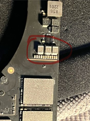
in the pic below the 3 components highlighted are to be getting 0.9V,0.9V,1.2V but I'm not getting anything this at all. please advise if you know what to test 1st so I can find the issue and correct it.
thanks!
Attachments
Constant loop means it's not in DFU mode. Best way to do it on these is to jump the "FORCE_DFU" pad to I believe 1.2V (verify on schematic to be sure). This must be done with the machine fully off, and must be jumped before and while connecting power, plus remaining jumped a couple seconds after power is connected. When in DFU mode it should stay at 5V on USB-C and pull around 100 mA (for Ace2 machines like M2 and older). Also double check everything, the CAD-format board views are weird as one side of the board will be inverted, so watch out for that. Ensure your NANDs are soldered with pin 1 in the correct position.so I attempted this on the M2 model and used the schematic you had provided. now I believe I have all the passive components and nands installed (correctly I had thought) after about 20+ hours of by hand and referencing the mouser projects listed and IC chips from AliExpress.
This initially seems straight forward in the sense that the board view, schematic and mouser project list collectively make it much easier to understand the designated locations of each component (but not stupid proof unfortunately lol)
so after finishing up and trying to connect to host Mac in dfu and ... NOTHING! no response.
Checked it to see if it accepts any power (via usb-c port), and indicator shows constant looping.
I figured ive messed something up along the way and wanted to know what's the best way to trouble shoot at this point?
I know I'm not getting power to newly installed "SSD_OC1VR1" circuit correctly.
in the pic below the 3 components highlighted are to be getting 0.9V,0.9V,1.2V but I'm not getting anything this at all. please advise if you know what to test 1st so I can find the issue and correct it.
thanks!
Hi! Just got my NANDs from aliexpress. Programmer says that it is preformatted for iphone 13pro. I didn't tried to solder them(i will start as is, it it will not work, will try to upload clean firmware)2 blank KICM223 NANDs will work fine on the M1 iPad Pro. You just have to make sure you install all the passive components for the second NAND if yours originally only had a single NAND.
I downloaded your KICM223-229-clean but there are 10 versions of clean nand. Wich one to use to set nands to clean state?
Thanks in advance!
Hi @dosdude1 if i have macbook air m2 512 gb with 2 nands and i want upgrade to 2tb i need only installing 2x blank HN3T3BAGCAX172 and thats all ? Or need i installing passive components ? Thanks 👍No, the passive components are the same on all models that I've worked on. On M3 Air with both NANDs already populated, installing 2x blank K5A8 NANDs should get you up and running.
Register on MacRumors! This sidebar will go away, and you'll see fewer ads.


