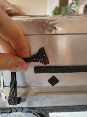
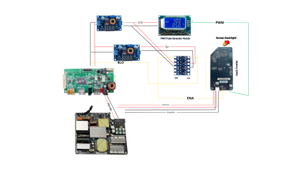
Hi again,I am not sure how to thoroughly check the apple inverter, but if you can confirm that the voltages at the plug with the 6 cables are correct then it may be the inverter. Your PWM module shows 13.3 which is correct. I have experimented with various frequencies between 1kHz and 20 kHz and they all worked. With the low frequency the screen starts to show some flicker. Check the cables going to the Apple inverter to make sure each cable goes to the correct pin.
I’ve connected everything and checked it all with the multimeter. Everything seems fine except for one thing: the ENA pin on the inverter is reading 1.61V. I’m not sure why—it’s supposed to be 3.3V.
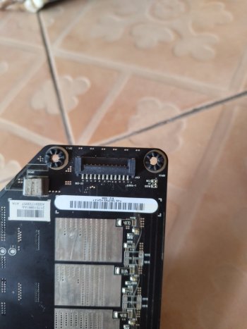
When i check the logic board , the wire is 3.3v. maybe is the inverter?