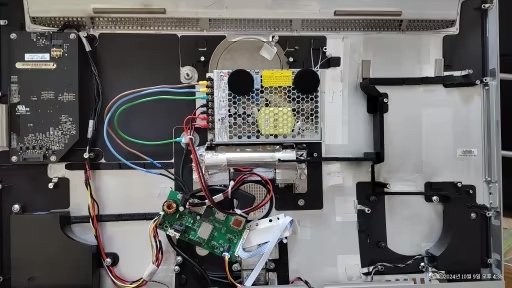
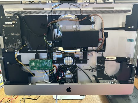
Here is a video dismantling an LG screen panel, showing the internal arrangement.
It's from a 5K iMac, but the screen panels are made the same way.
It's from a 5K iMac, but the screen panels are made the same way.
")
What temperatures are you experiencing that has you concerned? How hot is it getting?Hi Guys, my original inverter setup creates too much heat, and I am worried about it. I don't want to have more fans running and making more noise. So, has somebody tried a setup with the Chinese inverter board instead of the original inverter but still interfering to change the BLO voltage down from 5V to 3.3V and the ADJ/PWM frequency down to 13.3 kHz ? Comments and ideas are appreciated
The post you are referring to reporting the connection of wires from the LCD driver board directly to the original inverter is the only known instance of success doing this that I am aware of.Hi,
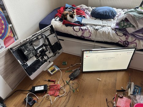
thanks to this thread and to several youtube videos, I also accepted the challenge and converted an iMac 2010 27", which had a broken mainboard, to an external display. It has the LM270WQ1-SDC2 panel and I ordered a board with DP, HDMI and 5V USB jacks. With the first board, the DP port was broken, but the seller from Ali sent a replacement part which finally works. I use the permanent 12V supply from the original PSU and I soldered the power button to the small keyboard that came with the conversion kit. At the moment, I am using the Chinese inverter board.
It's great that it works, but as expected, the brightness is a bit dim, especially when compared to the original screen of my iMac 2011, which is placed beside the converted monitor. Earlier in this thread, I remember some users reporting that they just connected the wires from the board to the original inverter of an iMac 2010 and it just worked (without PWM board, stepdown converter etc.). Also, one of the reviewers on the Ali product page posted an image, where the 6 cables of the board were connected to the black plug of the original Apple inverter. Unfortunately, the resolution of the photo is too low, so that it's not possible to figure out the exact pinout.
Reading this entire thread, I get the impression that it might be possible to do to with 2010 iMacs, but not with 2011. Are there any of you who can confirm that it works for a longer period of time (and also have not heat issues, etc.)? Would be really nice, because I still have the Apple inverter...
It is getting up to 50C at the temp sensor which means that it is at least 55C may be even more at the board elements mainly at the 6 inductors (I think they are inductors? ) of the original iMac inverter. I have an operational iMac as well, mid 2011, and it does not go up near 50C.What temperatures are you experiencing that has you concerned? How hot is it getting?
Can you post the schematics please.The post you are referring to reporting the connection of wires from the LCD driver board directly to the original inverter is the only known instance of success doing this that I am aware of.
All I can say is the iMac schematics are quite clear that the specs for the inverter input for the 2010 and 2011 (and probably the 2009 too, but I can't confirm with schematics I have seen) are 3.3 Vdc (BLO/ENA and PWM leads) and 13.3 kHz PWM signal for control and 12 Vdc (x2 leads) for power. If there is a way to obtain this using the LCD driver board it would probably work. I do not know of any boards that deliver this out of the box which is why I went with the step down board and PWM board to solve the issue of using the iMac inverter.
Regarding the image with the 6 cables connected to the black plug, we might be able to help if you copy and post the image you are referring to.
Hi. It is an output at least on my board. I tested it. The volume is very soft though even on max. A jack with 4 partitions was somewhat shaky, and I had to push it in a bit. Jack with 3 partitions was OK.Hi @bmwm3343ps, I guess the 3,5mm jack is not an audio output but an input. In the OSD there is an option to change audio input from digital to analog...
This may well be, I didn't test it. But there may also be different versions of the board. In the product description of my version, it just says "audio". However, regarding audio output I had a chat with the seller and he told me that audio output is possible via the blue 4-pin jack (PH2.0 4PIN). I ordered such a connector cable to connect the internal speakers, but didn't do it yet. There is also a YT video (with a japanese title, if I remember correctly), where this connection is used for audio output to the speakers (though with soldered wires).Hi. It is an output at least on my board. I tested it. The volume is very soft though even on max. A jack with 4 partitions was somewhat shaky, and I had to push it in a bit. Jack with 3 partitions was OK.
Correct about the blue connector. I have tested it and it does work. The product description for my board also says "audio" only.This may well be, I didn't test it. But there may also be different versions of the board. In the product description of my version, it just says "audio". However, regarding audio output I had a chat with the seller and he told me that audio output is possible via the blue 4-pin jack (PH2.0 4PIN). I ordered such a connector cable to connect the internal speakers, but didn't do it yet. There is also a YT video (with a japanese title, if I remember correctly), where this connection is used for audio output to the speakers (though with soldered wires).
Can you please post a link to YT video.This may well be, I didn't test it. But there may also be different versions of the board. In the product description of my version, it just says "audio". However, regarding audio output I had a chat with the seller and he told me that audio output is possible via the blue 4-pin jack (PH2.0 4PIN). I ordered such a connector cable to connect the internal speakers, but didn't do it yet. There is also a YT video (with a japanese title, if I remember correctly), where this connection is used for audio output to the speakers (though with soldered wires).
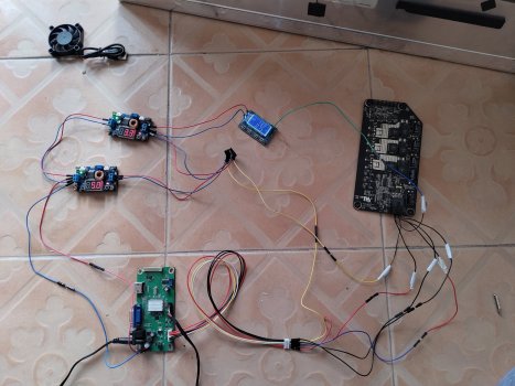
Happy to help... Let's try. What is the problemI know that the photo is kind of confuse but i need some help. This is my configuration.
Well, I followed the diagram that was posted on the forum, and after connecting the screen, I haven't gotten anything. I don't have a multimeter to check the voltage. I understand that something in the connection I made has failed.Happy to help... Let's try. What is the problem
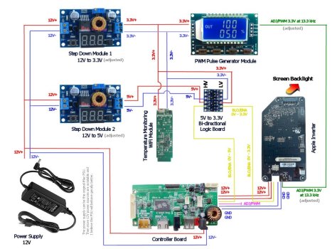
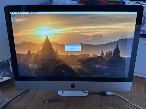
The screen works, I use it daily with the Chinese board. I hope it's not a fault with the model of this board.Hmm, I posted this diagram, and it worked for me straight out of the box. It is based on everything I have been reading here. Thats why I posted it. OK, let's see. It may prove difficult to troubleshoot if you don't have a multimeter. I followed your setup as far as I can do on the image. Check few thigs to start off.
1. Are you sure the screen and the inverter were working before you started with the conversion? Did you do a clean test only with the Chinese board and inverter?
2. Make sure the small logic board is connected correctly meaning the 5V +/- and the BLO from the Chinese board go to the HV site of the board and the 3.3V +/- and the BLO cable go from the LV site of the board into the original inverter.
3. I cannot see it clearly on the image you posted so I can't follow the cables going into the inverter, but make sure each cable goes to the correct pin on the inverter as described in other posts. On the diagram I posted here I have not described which cable goes to which pin of the inverter. It was clear to me because the pin descriptions are on the inverter it-self and also on the Chinese board (not necessary the way I have them lined up on the diagram).
Just as a clarification - I use the other Chinese board model in my setup as specified on the diagram I posted (hopefully this is not the problem in your setup).
On your Chinese board at the back of it, do you have a name/description for each pin?
I am not sure how to thoroughly check the apple inverter, but if you can confirm that the voltages at the plug with the 6 cables are correct then it may be the inverter. Your PWM module shows 13.3 which is correct. I have experimented with various frequencies between 1kHz and 20 kHz and they all worked. With the low frequency the screen starts to show some flicker. Check the cables going to the Apple inverter to make sure each cable goes to the correct pin.The screen works, I use it daily with the Chinese board. I hope it's not a fault with the model of this board.
On the other hand, I've gotten a multimeter, the voltages are correct, so I assume the problem is with my wiring scheme. I get quite confused with the double connections between the components.
Is there any way to know if the faulty component is my original Apple inverter? That's one of the possibilities I’m considering.
The other is that my multimeter doesn't measure Hz, so I’m unsure if the PWM signal is correct. At least the voltage is correct.
I will check the connections, especially to the logical board as you suggested
Can you please post a link to YT video.
| China Inverter | Apple Inverter |
| 12V | 12V |
| 12V | 12V |
| ADJ | PWN |
| BL_ON | BL_On |
| GND | GND |
| GND | GND |
where is the mistake?