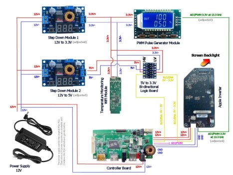
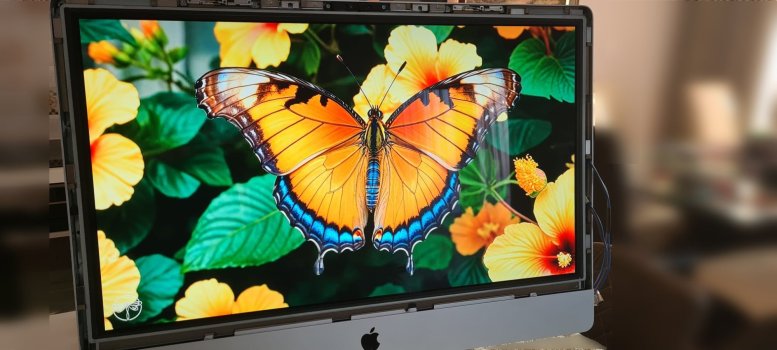
Hi Guys. I created a drawing with the boards and connections that I have currently of course based on all I have been reading and learning in this form. Thanks to everybody involved. It is attached to this message. I will appreciate it if somebody can check if I have messed up something on it. Also, a little picture of the result - screen with beautiful colours.
Some observations though:
1. Screen goes to sleep and back from sleep based on the attached HDMI device being switched off or switched on.
2. The colours I believe are better with the PWM module than without it.
3. The internal temperature is running slightly lower, but not by much so my next step will be to install the fans, but this is going to happen when the temperature sensor board arrives in about two weeks.
4. The duty cycle settings with the PWM board seem to be reversed - 18% is higher brightness and 100% no brightness
5. PWM below 15% makes the screen flicker rapidly.
6. In my setup all the boards stay powered because they draw power directly from the external PSU (I have an idea how to fix it but it involves management of the 220V to the external PSU which will work for me).
7. The power consumption at the moment when the screen has gone to sleep is about 1.2W and when the screen is on it is about 75-77W which is lower that the 85-87W before I installed the PWM module.
8. I added to my configuration a Temperature monitoring WiFi module just because I can, and I am very curious what's the story inside the box
")