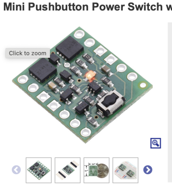
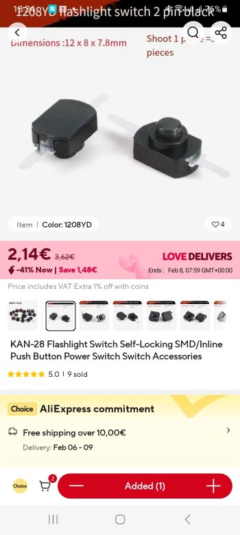
During the today lauch time, i tested the 12 6Amp porwer brick and dont work like we expected (the power brick complete turns off the led and dont provide power). I have to decide the way to go (Original PSU or 8Amp power brick). I dont like the ideia to add a push pull button, i prefer to keep the stand button to turn Chinese controller... @SubDriver @iMacConversionEnthusias
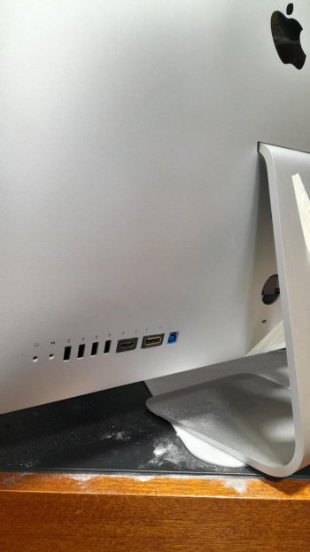
In the mean time, i have complete the holes at the back for the DP, HDMI and USB Upstream Ports, i like the way it ends")
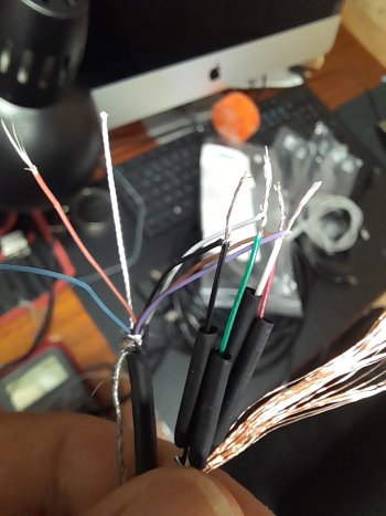
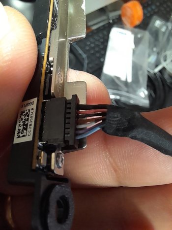
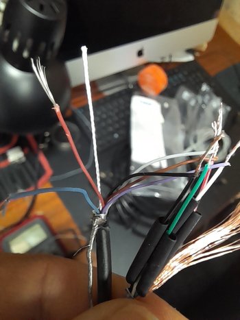
I need to buy a Headset jack that cutoff speakers when connect the audio jack, and design/print a part to secure the 4 USB ports at back inside...
In the mean time, i have complete the holes at the back for the DP, HDMI and USB Upstream Ports, i like the way it ends
I need to buy a Headset jack that cutoff speakers when connect the audio jack, and design/print a part to secure the 4 USB ports at back inside...