Become a MacRumors Supporter for $50/year with no ads, ability to filter front page stories, and private forums.

PaulD-UK

macrumors 6502a
Oct 23, 2009
869
468
Do you mean the Mac power button cables? One to wire 4 and the other to wire 7 of the control strip cable, making sure wire 7 is still connected to the control strip as it grounds the other switches.

Thank you for the data sheet, as I haven't seen that. Lots of information on it (with 'translate').
 

LeMelleKH2

macrumors newbie
Dec 30, 2022
27
17
Do you mean the Mac power button cables? One to wire 4 and the other to wire 7 of the control strip cable, making sure wire 7 is still connected to the control strip as it grounds the other switches.

Thank you for the data sheet, as I haven't seen that. Lots of information on it (with 'translate').
Yes! Like for the mac power cables themselves, does it matter which one connects to 4 and to 7? Also, connecting to 3 instead of 7 should work as well?
 

PaulD-UK

macrumors 6502a
Oct 23, 2009
869
468
The Mac power button contacts are electrically isolated, so it doesn't matter which way round it is connected.

On the control strip, wire 3 and wire 7 are both connected to a common ground, so either is OK.
 
  • Like
Reactions: LeMelleKH2

LeMelleKH2

macrumors newbie
Dec 30, 2022
27
17
The Mac power button contacts are electrically isolated, so it doesn't matter which way round it is connected.

On the control strip, wire 3 and wire 7 are both connected to a common ground, so either is OK.
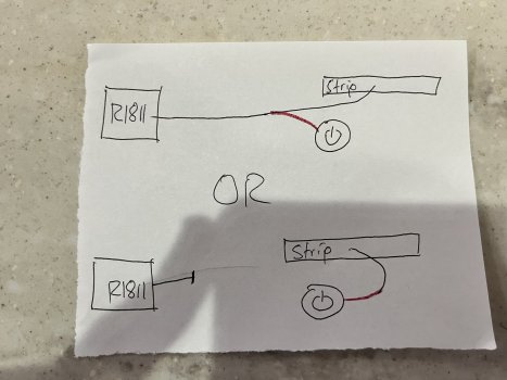
Got it! And when connecting the wires, I just have to make sure it's connected to the controller strip, not the r1811 board as well? Or should I splice the wire instead?
 

LeMelleKH2

macrumors newbie
Dec 30, 2022
27
17
Splicing the wires the safest option.
Sorry for another follow-up! Would splicing in either of these ways be okay? Or would one be preferable? Thanks!
 

Attachments

  • 017CAF95-2085-43CE-886E-9C9644D6C182.jpeg
    017CAF95-2085-43CE-886E-9C9644D6C182.jpeg
    413.9 KB · Views: 116

PaulD-UK

macrumors 6502a
Oct 23, 2009
869
468
Connecting to the cable is easy. Soldering to the PCB strip would require skill and special tools.
 

LeMelleKH2

macrumors newbie
Dec 30, 2022
27
17
Connecting to the cable is easy. Soldering to the PCB strip would require skill and special tools.
Soldering is no problem for me! Im most concerned about which connections need to remain. Like does there have to be a connection to the R1811, or is just the controller strip to the imac power cables good enough? Or from the r1811 board to the power cables, or all 3?
 

davidg5678

macrumors regular
Dec 5, 2020
128
108
Soldering is no problem for me! Im most concerned about which connections need to remain. Like does there have to be a connection to the R1811, or is just the controller strip to the imac power cables good enough? Or from the r1811 board to the power cables, or all 3?
The two wires from the iMac's power button should touch the two points on the R1811 board that corresponds to the power button.

From what I've read above, it sounds like the key connection points are between the ground and pin 4. Polarity (which specific wire from the iMac's button goes to which pin, 4 or 7) doesn't matter as this is just a simple button. A connection to the ground can likely be found at any number of places on the R1811 board, but it sounds like pin 7 is a convenient one to use.

As to where you actually solder the wires, I believe that there are several points along the circuit that would potentially work:
1) Solder the iMac button wires to the bottom of the R1811 board, where the button board plugs in. (You'd need to ID the pins that correspond to wires 4 and 7 first.)
2) Splice the iMac button's wires in line with the button board's wires.
3) Solder wires to the bottom of the button board, underneath where the connector sits.
4) Carefully solder wires directly to the metal pins sticking out of the power pushbutton mounted on the R1811 button board.

Keep in mind that the R1811's button interface board doesn't have any fancy computer chips on it --it's just a bunch of buttons and wires connected to the main driver board. As far as the driver board is concerned, as long as the two power button pins for the R1811 touch the two power button wires for the iMac's button, this should work.

If you'd like to better understand this circuit, I would recommend that you get a digital multimeter with a buzzer for continuity testing, and try to probe the circuit at the different locations I've described above. If you want to test that you have successfully located the two points you need, the multimeter will beep when the R1811 button is pressed. After this, you can splice in the original iMac button and see if it works too. Using a multimeter lets you test this without plugging in the expensive board when you potentially stand to short-circuit things with live electricity.
 
  • Like
Reactions: Sigsgaard

yaosiang

macrumors member
Jul 3, 2010
57
47
Soldering is no problem for me! Im most concerned about which connections need to remain. Like does there have to be a connection to the R1811, or is just the controller strip to the imac power cables good enough? Or from the r1811 board to the power cables, or all 3?

As @davidg5678 explained above, you should understand the circuit by carrying out continuity test using a multimeter before (and after) carrying out any alterations. Otherwise, you risk damaging the driver board!

There are many ways to connect the iMac power button to the main driver or interface board.

You can directly solder the 2 wires from iMac power button to the + and - of the push button. Underneath the interface board, there are 2 solder pads for - and 2 solder pads for + which are easily accessible for soldering.

CY5Key.png
 

davidg5678

macrumors regular
Dec 5, 2020
128
108
I've installed the R1811 driver board in my 2014 5K iMac. For the most part, things work normally, but I've noticed that there is a strange uneven pattern of dim regions in the backlight towards the bottom of the screen. Does anyone know what this problem is, or how I can fix it? Thanks!
PXL_20230116_004817932(1).jpg
 

LeMelleKH2

macrumors newbie
Dec 30, 2022
27
17
My Ultimate 5K Build is Finally Complete!
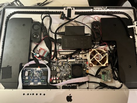
Thank you to everyone for the help! My rig is finally complete! This was my first DIY project, so I was bit nervous but still excited to dive in. Using Gold's setup as inspiration, I ended up installing an 8-speaker system as well, with a temperature control system. Just wanted to give some of my thoughts and add some other tips and perspective.

61C16403-A211-42DD-9CBC-E0F516D039D2.jpeg


Power:
There are many ways to connect the iMac power button to the main driver or interface board.

You can directly solder the 2 wires from iMac power button to the + and - of the push button. Underneath the interface board, there are 2 solder pads for - and 2 solder pads for + which are easily accessible for soldering.
For the iMac cables, I ended up soldering to the back of the power switch. The pins at the cable portion were so close together that it made sense to use the pins that were more spaced out. I verified with a multimeter that the positive side has continuity with the power (pin 4), and the negative with the ground (pin 3).
IMG_3863.jpeg


To retain the original power supply, I used self solder connectors. In hindsight, I probably would have soldered first, but I only learned to solder after doing that part and wasn't confident on it yet.

I really like the Alitove power supply units. I ended up using that for the 24V supply. Funnily enough, the 5A unit is bigger than the 6A unit. The 6A fits nicely between the posts as shown, while the 5A is just too big to fit snugly there. With all the extra components I added, it worked out nicely to just go for 6A. The 18V supply needed for the amp works really nice as well. For the amp, it ranged from 12-19V, with 16V recommended. It's tough to find a 16V supply without needing a converting plug piece (all I saw for 16V were for some printers/scanners, which had the wrong size for the plug adapter). Alitov's 19V was too big to justify, compared to the one I ended up getting, so it ended up just saving space in the long run.
IMG_3870.jpeg


Audio:
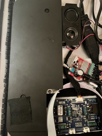
I used a 2 x 15W + 30W amplifier, which had enough terminals to install the full 8-speaker system easily. Initially I was going to hook resistors in parallel to help achieve 8 ohms in every speaker, but the power consumption that the resistors draw would have made the system worse off, so I just connected the speakers in series. The woofers end up at the 8 ohms, and while the speakers are at 12 ohms, it is plenty powerful.

69497953646__D9F7A174-B08D-495A-907D-C6149B03B017.jpeg


For the terminals, I highly suggest using ferrule crimps, as it makes it look nice and clean, without any risk of wires touching each other. I did notice them falling off at first, because the wires are pretty small. I also crimped the plastic piece to ensure a good connection. I didn't bother seeing if the on-board speaker connection worked or not, and it seems to be mislabeled in the first place, and the amplifier does a great job. I also cut some plexiglass and sanded it down, to attach to the botton of the amp. I wanted to ensure that no metal contact would be made, so I added that extra layer of security. The wires in the extra speakers are far too long for the Left side, so I cut that down and used it extend the cables on the right.

As for the imac speakers, I think the diagram of which connector is which is wrong, as the tweeter cables controlled the woofer and vice versa, according to my labels. Some of my labels did fall off (ughhhh haha) so I doubled checked the polarity of the woofer, using a 9V battery, and made sure the speaker moved outward when I connected. The tweeter was harder to verify, since it doesn't move noticeably. I simply played trial and error by connecting all four speakers up. I tested every permutation, and the one that sounded best was the correct one, as the others phased out elements of the sound, making it sound awful.


IMG_3868.jpeg


Temperature:
I was going back and forth on if I should install the temp control rig. Gold verified that the system doesn't really get hot enough to necessarily warrant it, but I was not sure how much heat the amplifier would generate, since mine can output 20w more than the Dollatek amplifier Gold used, so I decided to go for it. I actually found this part really easy. I used a Noctua 80mm as well. I had the 4-pin but it doesn't matter; you only need two of the cables.


This site is fantastic for understanding the W1209 board. Gold's amplifier has a power out, but mine didn't, so I spent some time trying to figure out how to power this joint. For power, because I pulled the factory fan, there was a convenient 12V power connector right on the board, saving me from having to buy another supply. To connect the fan, I simply cut the yellow and black wire from the fan (I then securely taped the green and blue wires), and cut the cable from the stock fan, so you don't have to buy two pins connectors.

From left to right the cables connect:
image-35.jpeg

K0: The yellow wire from the fan
K1 and +12V: Split the red wire from the stock fan connector into 2, and connect to each respective terminal
GND: Combine the black ground cable from the fan and stock fan connector

I also used ferrule crimps here.

I set the temperature to 70C, the hottest it's gotten for me so far is low 40s, but the system works seamlessly, and you don't have to change any other settings.
IMG_3869.jpeg


Installation:

I used velcro to put the components in place. It is extremely strong velcro, and I have no worries of anything falling out. Trying to plan out the system was challenging, but I found a good layout in the end. Unfortunately it only allows me to connect the thunderbolt cable, but I don't mind. If that's a big deal to you, there might be a different layout that works, but with all of my extra components, including the extra LED backlight it was a sacrifice that I had to make. I also needed a right angle extension for the power supply on the board, as the straight connection did not fit.

For the controller strip, I drilled holes into the front. I was nervous the drill would bend the front panel, but it's plenty sturdy, especially since I applied upward force against it. Because of this, I actually hand-drilled the hole initially, then expanded them. I'd say you don't really need to do this, but if you want the most accurate, I would recommend it. It's a alot of work but pays off. I noticed without hand-drilling, even with a nice center punch, the drill would more likely veer off slightly; this happened with the holes that I used for the screws, cuz I was dreading having to hand-drill two more holes. For the drill bits, the holes for the buttons were 1/4 ; the hole for the LED was 3/16; and the holes for the screws were 9/64

To protect the strip from some of the metal, I deburred the hole as a best as I could, then placed a piece of electrical tape to line up with the hole. THIS was a pain in the ass, as there is no room to line the tape up to the hole, as I cut the holes into the tape first (highly recommended, so you can really get a clean hole in the tape). Initially I was just going to tape the strip once it was lined up to the holes, but there's not a lot of room to really latch the tape onto. Conveniently, the strip has holes for mounting, so I used two nylon screws with a nut to secure it in place. It's very secure! I also put some push-button caps to make it look nice and make using the button easier, glued with some E6000.
IMG_3878.jpeg


Quick aside: for the iMac power button, make sure it's cable is in FRONT of the left speaker, otherwise the cable gets in the way of the pushing mechanism and the button won't feel tactile and it will be very gummy.

Unfortunately, the ports are just too small to get the Thunderbolt 3 cable through. I used a hacksaw blade, bent it 90 degrees so I could hold it on the other side, and cut the USB-C and Ethernet port together. I put some electrical tape to protect the cable, then aluminum tape along everything, to make it look a bit sleeker.
IMG_3879.jpeg


Thank you to everyone who helped me out, Paul, Citivilous, David and YaoSiang; and and tdiggity and hybridfrost on Reddit!

Links:

R1811 Board:


LED Backlight Driver:

Stonetaskin Speakers:

Audio Amplifier:

Headphone Cable:

W1209 Temperature Control Board:

Noctua NF-A8 PWM:


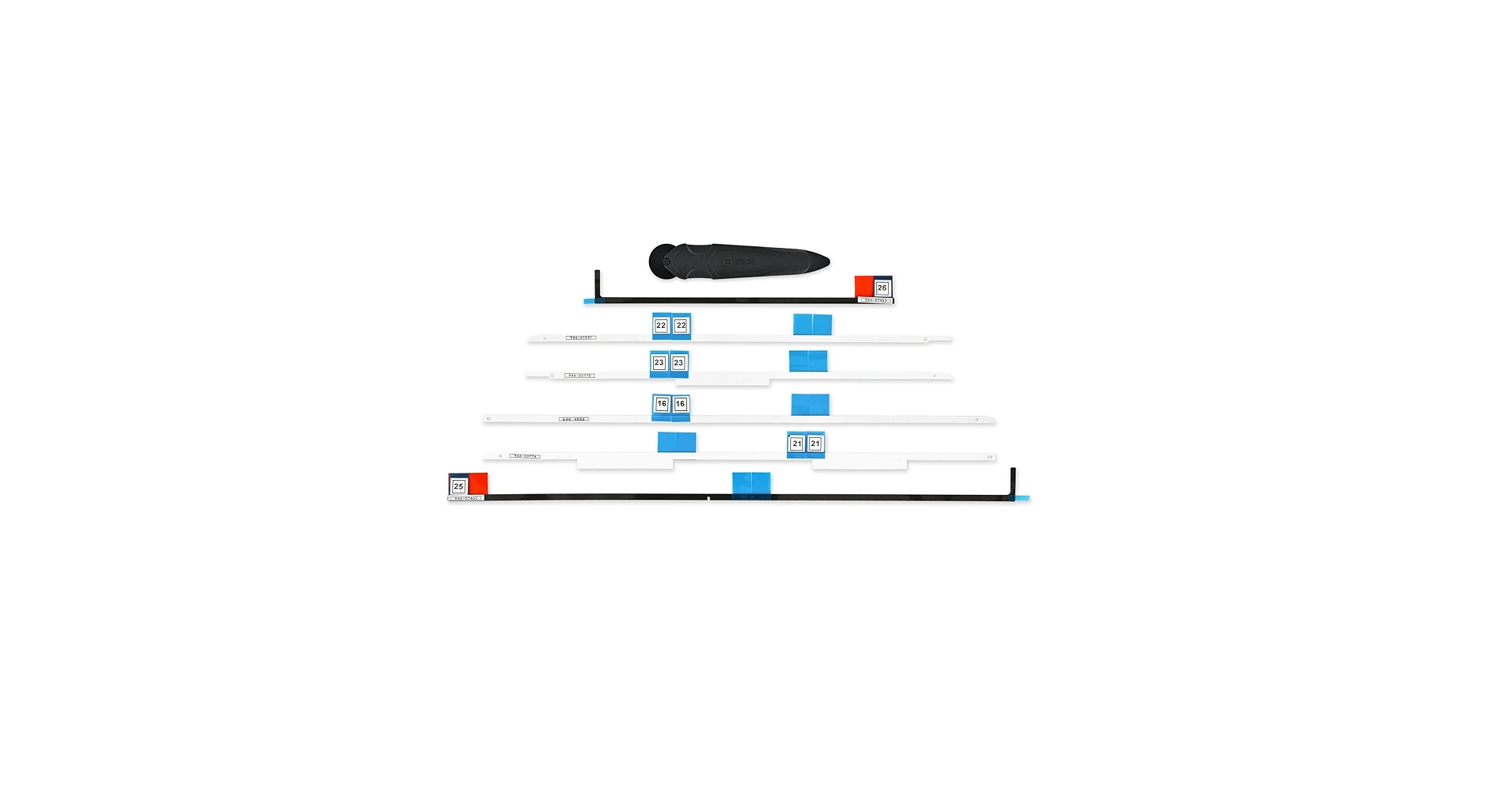
iFixit Adhesive Strips:


Alitove 24V 6A Power Supply:

18V Power Supply:

Power Supply Splitter:

Right-Angle Power Extension Cable:

Nylon Screws and Bits:

3M Fasteners:

Velcro:

Thunderbolt 3 Cable:

Drill Bits (AWESOME for metal):

Deburring Tool:

Ferrule Crimping Tool and Crimps:

Push-button Caps:
 

Attachments

  • IMG_3871.jpeg
    IMG_3871.jpeg
    543.7 KB · Views: 155
  • ADD0D07A-B593-4098-82E0-693D56683965.jpeg
    ADD0D07A-B593-4098-82E0-693D56683965.jpeg
    582.9 KB · Views: 147
Last edited:

PaulD-UK

macrumors 6502a
Oct 23, 2009
869
468
Hi, thanks for all the pics. Nice information :)
A couple of points:
How is you screen Backlight connected? It still seems (in the pic) that the cable to the backlight for the screen is connected/powered by the R1811 board, while the LP0818 board seems to have nothing connected to its outputs (only the input from the R1811).
And does the Noctua fan have a cool air inlet in the rear of the case?
 

LeMelleKH2

macrumors newbie
Dec 30, 2022
27
17
Hi, thanks for all the pics. Nice information :)
A couple of points:
How is you screen Backlight connected? It still seems (in the pic) that the cable to the backlight for the screen is connected/powered by the R1811 board, while the LP0818 board seems to have nothing connected to its outputs (only the input from the R1811).
And does the Noctua fan have a cool air inlet in the rear of the case?
So that one cable that connects between the R1811 and LP0818 is enough to facilitate the connection between the two, and the difference is honestly night and day. Then I just used the installed backlight cable on the r1811 to connect to the display.

I do not! It may be something to consider yeah! I never really thought about that hahaha, the grate is close to where I put the fan, but that may be something Ill edit in the future!
 

PaulD-UK

macrumors 6502a
Oct 23, 2009
869
468
"So that one cable that connects between the R1811 and LP0818 is enough to facilitate the connection between the two, and the difference is honestly night and day. Then I just used the installed backlight cable on the r1811 to connect to the display."

The cable to the LP0818 is not two-way for backlight power.

All the R1811 board supplies is 12 volt + and - , an ID bit-switch (so it knows when the LP0818 is plugged in), and a variable voltage 0-5v which controls the adjustment of the brightness level - varying the output voltage of the LP0818 on its two 4-pin output connections.

So my guess is that by plugging the LP0818 cable into the R1811 you are overriding its inbuilt brightness level control for the R1811's own backlight connection, which is reverting to full 100% brightness.
It expects the LP0818 to be varying the backlight brightness.

Does the brightness level on the key strip menu control still work normally?
 
Last edited:

LeMelleKH2

macrumors newbie
Dec 30, 2022
27
17
"So that one cable that connects between the R1811 and LP0818 is enough to facilitate the connection between the two, and the difference is honestly night and day. Then I just used the installed backlight cable on the r1811 to connect to the display."

The cable to the LP0818 is not two-way for backlight power.

All the R1811 board supplies is 12 volt + and - , an ID bit-switch (so it knows when the LP0818 is plugged in), and a variable voltage 0-5v which controls the adjustment of the brightness level - varying the output voltage of the LP0818 on its two 4-pin output connections.

So my guess is that by plugging the LP0818 cable into the R1811 you are overriding its inbuilt brightness level control for the R1811's own backlight connection, which is reverting to full 100% brightness.
It expects the LP0818 to be varying the backlight brightness.

Does the brightness level on the key strip menu control still work normally?
Ohhh I see now! I uploaded an older photo. I connected the two connectors from the cable that connects to the display (with the pointed pins) to each connector on the other side. It’s still controlled by the strip yeah
 
  • Like
Reactions: PaulD-UK

prkkk

macrumors newbie
Jan 4, 2023
2
0
Yes, this is what I ordered:

20 Sets Jst 2.0 Ph 4 Pin Connector Plug, Include 10 Sets Mini 4 Pin Jst Ph2.0 Connector Plug Female with 150mm Cable Wire & 10 Piece Male Micro Jst Ph2.0mm 4Pin Connector Plug https://www.amazon.com/dp/B08RHGT3W3?ref_=cm_sw_r_apin_dp_DA8FGDP37HG6HJFRRPXK

I have a few extra so if you want to PM me your address I can mail you some.
Hi, I got same Jst connector but still cant understand how to connect to 2 speakers 4 pins to this single 4 pin connector. Board speaker socket notes L+, L-, R-, R+ does this imply we need to connect left speaker pins to L+, L- on board. This conradicts Y shaped connector to connect left, right speaker pin to board pin. Also. on imac speaker, I cant find which one is pin 1 as they look identical. Thanks much
 

prkkk

macrumors newbie
Jan 4, 2023
2
0
Some comments on your post:

I guess used 2020 iMacs are still more expensive than older ones and in terms of the screen there is not much difference (2014 – first 5k, 2015 – first with P3 support). Also 2020 iMacs wern’t a good deal back them since they were not as upgradable as previous models.

1) Safety – I personally use a Thunderbolt dock inbetween the screen and the laptop. Makes it a bit more expensive but you might feel more safe. Alternatively you could go with an adapter that merges two DPs into a USB-C. That would be a middle link to feel more safe.
2) Noise – honestly, I’m totally fine with the default fan (I use R1811). I actually tried Noctua fan featured in this thread but to me it was more loud (not much but tiny bit).
3) Brightness – 5k panels of 2014 and 2015 don’t require another converter, every panel after 2015 including 2020 does require an additional board to reach the max brightness.
4) Hassle / Reliability – well this DIY project requires some hassle by definition, doesn’t it? :)

Other things you’ve mentioned:
- Since you do bother about the max brightness, I would suggest to bother about 10 bit as well (or don’t bother about both – your screen will get quite bright (really bright!) without an additional board). So and it you wish to go with 10 bit, then R1811 is your choice.
- Can’t say about controlling with the keys but there is a 3rd party app (listed somewhere in this thread) that allows to change brightness without going to the menu
- It is possible to reuse the built-in speakers but it requires some hassle that you wish to avoid. Basically you have four pins on each speaker (A1, B1, C1, D1 and A2, B2, C2, D2) and four pins on the board (W, X, Y, Z). And you have to manually make Y-shaped wires that will connect A1+A2 to W, B1+B2 to X and so on. The seller of R1811 offers custom speakers that already have Y-shaped wires, so all you‘ll need is to connect them to the board. But then you’ll have to remove the original speakers…

Overall it’s up to you what level of hassle/perfection you wish to have. There are lots of things you can skip: making the original power button working, making the power go via original cord, support additional cables/ports, put the board and power brick inside or outside of the case…

Good luck and hope you’ll succeed!

Oh and one thing to mention that was quite a bummer for me. If you calibrate your display and adjust RGB values – once you turn board’s power off – all those settings get reset. That’s annoying and AFAIK there is no hardware fix for that yet.
On board 4 pin socket notes, L+, L-, R-, R+ . Does this imply left, right speaker connection. If so this implies, A1+C1 goes to W not A1+A1 to W. what am I missing. Thanks much
 

webhdx

macrumors newbie
Jan 16, 2023
9
10
Hey guys,
I'm thinking about converting 5K Retina iMac to an external display. I still can't figure out a few things:
* Did anyone try to design a PCB that would route connections from driver board to port cutouts in the case?
* What is the simplest amp to power internal iMac speakers?
* What USB camera offers the best image quality and still fits?
* Does HDR work with these AliExpress driver boards?

As you can see I'm trying to basically include all the features, especially internal speakers to save some space on my desk.

And in general I'd like to ask you how do you like this setup compared to LG Ultrafine 5K or Studio Display. Are there any issues or things that bother you during everyday use?
 

davidg5678

macrumors regular
Dec 5, 2020
128
108
Hey guys,
I'm thinking about converting 5K Retina iMac to an external display. I still can't figure out a few things:
* Did anyone try to design a PCB that would route connections from driver board to port cutouts in the case?
* What is the simplest amp to power internal iMac speakers?
* What USB camera offers the best image quality and still fits?
* Does HDR work with these AliExpress driver boards?

As you can see I'm trying to basically include all the features, especially internal speakers to save some space on my desk.

And in general I'd like to ask you how do you like this setup compared to LG Ultrafine 5K or Studio Display. Are there any issues or things that bother you during everyday use?
1) I don't know of any such PCB. I suppose if you are working with a 5K iMac that has USB-C ports, you could theoretically mount a connector behind the hole in the aluminum. In my opinion, it is far easier (but admittedly less elegant) to just pop out the RAM door, and run whatever wiring you need out through the big hole in the iMac chassis. A PCB large enough to span all of the ports would likely be prohibitively expensive to make any sense. I guess a smaller PCB and a 3D-printed bracket could be used, but that is a ton of work when there is already a huge hole in the back of the iMac. Perhaps some panel-mount connectors mounted on a 3D-printed RAM door replacement would make more sense.

2) The R1811 driver board already has an onboard speaker amplifier. If you see some of the above posts from this week, there is some discussion of using this amplifier to power the iMac speakers. Connecting the speakers would be a matter of cutting and soldering the right wires from the original speakers. (Personally, I went with better-sounding external bookshelf speakers instead, which is how I previously used the iMac before converting it into a monitor. I do see the benefit in having an all-in-one solution with speakers built-in if limited desk space is a concern.)

3)I know of some smaller USB cameras that fit, but the image quality isn't fantastic. The easiest way to get the best video quality would be to use an external webcam sitting atop the iMac (this looks a little less neat, but it wouldn't take up extra desk space :)) --if you run the webcam USB wire through the RAM hatch, the webcam's USB cable can plug directly into the USB port on the R1811 board, so the webcam will show up over the primary R1811 USB-C. If you are up for a soldering challenge, it should theoretically be possible to reuse an existing iSight camera from another Apple product or to use a PC laptop webcam module. Many, but not all, webcam modules use USB as their communication protocol, so it would be a matter of determining their pinout and soldering the right wires to a USB cable.

4) I believe the driver board itself supports HDR, but most of the available iMac panels themselves do not. The 2020 iMac LCD panel might work with HDR, but I haven't heard of anyone who had success with this before. To achieve enough brightness for the HDR spec, you would almost definitely need to use the constant current LED driver board in addition to the R1811 board.

5) I would make sure you find a power supply that is really well suited to the task of running all these electronics. I have not been completely satisfied with the one my R1811 came with, as it gets really hot and sometimes seems to struggle. I've been meaning to replace it with something of higher quality, with a greater amperage output.
 

chrisclausie

macrumors newbie
Dec 15, 2022
12
2
1) I don't know of any such PCB. I suppose if you are working with a 5K iMac that has USB-C ports, you could theoretically mount a connector behind the hole in the aluminum. In my opinion, it is far easier (but admittedly less elegant) to just pop out the RAM door, and run whatever wiring you need out through the big hole in the iMac chassis. A PCB large enough to span all of the ports would likely be prohibitively expensive to make any sense. I guess a smaller PCB and a 3D-printed bracket could be used, but that is a ton of work when there is already a huge hole in the back of the iMac. Perhaps some panel-mount connectors mounted on a 3D-printed RAM door replacement would make more sense.

2) The R1811 driver board already has an onboard speaker amplifier. If you see some of the above posts from this week, there is some discussion of using this amplifier to power the iMac speakers. Connecting the speakers would be a matter of cutting and soldering the right wires from the original speakers. (Personally, I went with better-sounding external bookshelf speakers instead, which is how I previously used the iMac before converting it into a monitor. I do see the benefit in having an all-in-one solution with speakers built-in if limited desk space is a concern.)

3)I know of some smaller USB cameras that fit, but the image quality isn't fantastic. The easiest way to get the best video quality would be to use an external webcam sitting atop the iMac (this looks a little less neat, but it wouldn't take up extra desk space :)) --if you run the webcam USB wire through the RAM hatch, the webcam's USB cable can plug directly into the USB port on the R1811 board, so the webcam will show up over the primary R1811 USB-C. If you are up for a soldering challenge, it should theoretically be possible to reuse an existing iSight camera from another Apple product or to use a PC laptop webcam module. Many, but not all, webcam modules use USB as their communication protocol, so it would be a matter of determining their pinout and soldering the right wires to a USB cable.

4) I believe the driver board itself supports HDR, but most of the available iMac panels themselves do not. The 2020 iMac LCD panel might work with HDR, but I haven't heard of anyone who had success with this before. To achieve enough brightness for the HDR spec, you would almost definitely need to use the constant current LED driver board in addition to the R1811 board.

5) I would make sure you find a power supply that is really well suited to the task of running all these electronics. I have not been completely satisfied with the one my R1811 came with, as it gets really hot and sometimes seems to struggle. I've been meaning to replace it with something of higher quality, with a greater amperage output.
Hello David. I bought this USB web cam and it is not showing up in OSX. I currently have it plugged into the R1811 board and the R1811 board is connected via single DP 1.4 cable. Is this sufficient or should I plug in the USB-C as well or extend the USB plug to plug it directly in the my Mac? Thanks for the help
 

chrisclausie

macrumors newbie
Dec 15, 2022
12
2
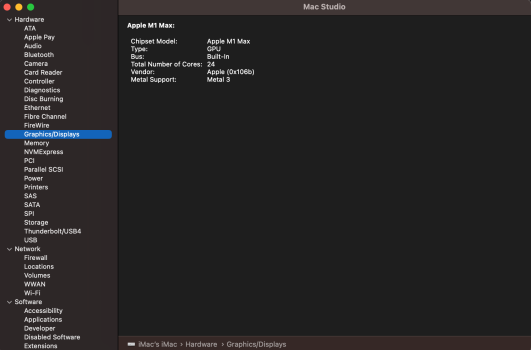
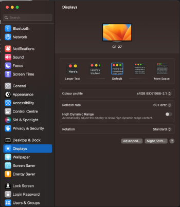
Also an open question, is there a way to confirm 10bit colour from the R1811 in OSX Ventura? My System Info shows no screens and in Display settings, I only get dumbed down details. Also my display shows up as G1 27 Display, is that normal? Is it worth upgrading the firmware to the latest floating around here, but you might lose remote use?
 

Attachments

  • Screenshot 2023-01-22 at 8.20.11 pm.png
    Screenshot 2023-01-22 at 8.20.11 pm.png
    194.9 KB · Views: 122
  • Screenshot 2023-01-22 at 8.15.58 pm.png
    Screenshot 2023-01-22 at 8.15.58 pm.png
    500.8 KB · Views: 125

davidg5678

macrumors regular
Dec 5, 2020
128
108
Hello David. I bought this USB web cam and it is not showing up in OSX. I currently have it plugged into the R1811 board and the R1811 board is connected via single DP 1.4 cable. Is this sufficient or should I plug in the USB-C as well or extend the USB plug to plug it directly in the my Mac? Thanks for the help
Displayport doesn't pass through USB signals, only video signals. The USB-C connector should send power, video, and USB all at once. If your computer supports USB-C, you can use it instead of displayport. If your computer doesn't support USB-C, you'll need to directly plug the webcam into a USB-A port on your computer (a USB 2/3 extension cable is probably fine).
 
Register on MacRumors! This sidebar will go away, and you'll see fewer ads.