Become a MacRumors Supporter for $50/year with no ads, ability to filter front page stories, and private forums.

•MacMike•

macrumors newbie
Aug 22, 2017
7
4
Found this well-written write-up on these driver boards and compatibility.

 
  • Like
Reactions: profcutter

•MacMike•

macrumors newbie
Aug 22, 2017
7
4
Anyone on here do this?
Love the custom 3d printed mounts.
I would pay someone to make and send me mounts like this!
A14371eef143c4eebab5960d8157c43f7D.jpg
 

LeMelleKH2

macrumors newbie
Dec 30, 2022
27
17
Hey man! I'm looking to do something similar and install a speaker system like yours. I was wondering if you could explain your power setup and how you connected that rig up? I'm also a little confused on which speaker wires to connect?
My Ultimate 5K Build is Finally Complete!


Power:


Usb-powered NVME drives work perfectly plugged into the driver board. Buy any of those portable NVME enclosures to USB adapters.

View attachment 1993014


—————

Driver Board, and Temperature Control + Heat:

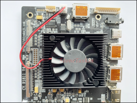
I can confirm after 8 months of using the driver board without a fan, it hasn’t overheat or shut down at all (with 1 inverter). Since most of you aren’t going to have 3 separate inverters like my final setup, I’m pretty comfortable recommending just taking the fan out. With these 3 inverters now, just to be safe I purchased a 12V Noctua 80mm fan to plug into the 12V amplifier power ports. (Uses .84W) of power so it shouldn’t decrease audio output by any recognizable amount. After wiring up the fan, I very quickly became quite uncomfortable with he noise level, even with the quiet wire than decreases the fan speed. (I like a silent / near silent computer. At the same time though, I did want the computer to cool down when (and only when) the temps became a little too hot for comfort. While I don’t think it’ll hit temps like that, Its nice to have the option for a backup. This is where the temperature controller came in. (LED) in the right hand corner. This thing was a pain in the *** to setup. In case you decide to include one in your build, wiring (from left) is +(fan wire), +12vPower input, +12vbridgedPowerInput, and -Power input. Setup videos are available on YouTube. A lot of people online shorted these boards out. (I shorted 2 of them and had to wait for another order. 3rd time was the charm. The shorts came from installing the screws from the back (instead of the front) or from the wiring being so close together. This was fixed with a bit of soldiering so only 1 wire went into any terminal. I set the thermostat to turn the fan on at 180º F / 82.2ºC. So far the fan has yet to come on. Temps with the screen perched against the case (after an hour) ran up to the mid 30ºC range with my apartment being at 74ºF. (pic provided). I did remove the screen after 5 hours of use to see what temps the thermostat was picking up inside, and it looks like the average internal ambient temp was sitting at about: 39.6ºC (103ºF). The screenful maybe 10 or 15 degrees hotter. Because of the (still very large (~70ºC) temp gap, I moved the temp sensor to above the fan and below the main inverter mounted to the display, since that's the most expensive part of all of this. Then I took the back-of-the-display temperature (unmounted to the chassis but running) read at around 44ºC (111ºF).

View attachment 1993040

—————

iMac speakers:

(original amps- Replaced):
View attachment 1993015
Initially I tried driving the iMac speakers with the 5v 2A PSP inverter.(product No. below) coupled with (2x) 5w + 5w amplifiers. (One right one left). While I was able to hear it (barely) the power was horrendous and far from what you’d expect from iMac speakers. Both the amps and power adapter were replaced / used for something else.

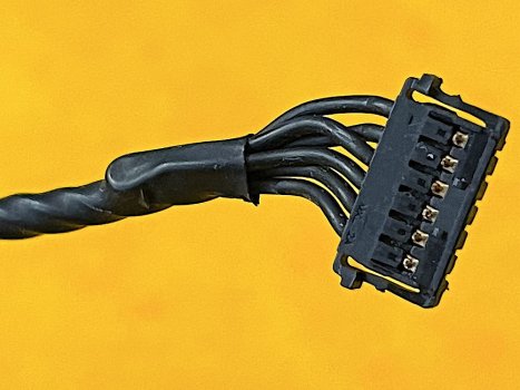
You’ll see 6 wires coming off of the iMac speaker connector. Clip the connector off. You’ll need to extend the length of the wire with some random wire you have around ( you can use the Stonetech speaker wire if you purchased). Roll back the sheathing. 2 of the connectors are not in use, leaving you with only sub+, sub-, tweet+,tweet- per speaker. To find which ones which I just connected them to the 10W amp. It was pretty clear which one was which. Subs were connected to the 20W output.Tweets to the 10W. The secondary speakers were also connected to the 10W. They sounded really nice connected to the 10W’s as mids. iMac and secondary Speakers were eventually powered by a 12V 5A 60W inverter, coupled with a 20W+10W+10W 12V amplifier. The 4 pin audio out on the driver board didn’t end up working, it was much easier just connecting the aux cable to the audio jack.


—————

Audio setup:

I connected the amplifier to a Y splitter M => FF aux cable. The females connected to the aux cable coming straight from the driver board and 1 cable connected to the bluetooth audio out.

View attachment 1993017


View attachment 1993093
 

LeMelleKH2

macrumors newbie
Dec 30, 2022
27
17
Thanks, I was able to connect the speaker wires and see what you mean--the amp on the R1811 board is very powerful!
Hi! I was wondering how you connected the wires to the connectors? Each of my imac speakers have 6 wires and I cant find a diagram indicating which is which. Thanks!
 

PaulD-UK

macrumors 6502a
Oct 23, 2009
869
468
From top to bottom in this pic (with the contacts facing you):
1. Woofer +
2. Woofer -
3. ID link + connected to
4. ID link -
5. Tweeter +
6. Tweeter -
You can see 3 is looped back to 4 in this pic.

iMacSpeakerConncetionCU.jpg


To connect to the R1911 board maintaining the correct 4Ω impedance of the speaker units you could use a 10 microFarad capacitor in series with the tweeter, and a 0.32 milliHenry inductance (coil) in series with the woofer.
EDIT: A better value is 0.15 milliHenry for the inductance coil.
In practice you could forget about the inductance coil with no problems.

TweeterProtectionCircuit.png


Presumably citivolus just connected the tweeter and the woofer in series (one after the other) to connect directly to the amplifier on the R1811.

FWIW here are the two driver units inside the iMac speaker units. Tiny !
iMacSpeakerInterior.jpg

l
 

Attachments

  • iMacSpeakerConncetionCU.jpg
    iMacSpeakerConncetionCU.jpg
    91.3 KB · Views: 67
Last edited:

LeMelleKH2

macrumors newbie
Dec 30, 2022
27
17
From top to bottom in this pic (with the contacts facing you):
1. Woofer +
2. Woofer -
3. ID link + connected to
4. ID link -
5. Tweeter +
6. Tweeter -
You can see 3 is looped back to 4 in this pic.


To connect to the R1911 board maintaining the correct 4Ω impedance of the speaker units you could use a 10 microFarad capacitor in series with the tweeter, and a 32 milliHenry inductance (coil) in series with the woofer.

View attachment 2135892

Presumably citivolus just connected the tweeter and the woofer in series (one after the other) to connect directly to the amplifier on the R1811.
Thanks so much!
 

LeMelleKH2

macrumors newbie
Dec 30, 2022
27
17
That’s correct!
Got it, thanks!! Oh! And what's the order of the pins on the board? Unless I missed that in an earlier comment, sorry!
 

Attachments

  • 5K-universal-DIY-HD-R1811-driver-board-USB-C-HDR-Freesync-EDP-VBO-144Hz-DP1-4.png
    5K-universal-DIY-HD-R1811-driver-board-USB-C-HDR-Freesync-EDP-VBO-144Hz-DP1-4.png
    2.2 MB · Views: 135

PaulD-UK

macrumors 6502a
Oct 23, 2009
869
468
Left to right in your pic:
L+ L- R+ R-
EDIT: Should be L+ L- R- R+.
See post #364 page 15 of this thread.
 
Last edited:

LeMelleKH2

macrumors newbie
Dec 30, 2022
27
17
Left to right in your pic:
L+ L- R+ R-

See post #364 page 15 of this thread.
On this diagram of the pins it has L+,L-, R- then R+, just wanted to clarify which direction is correct?
 

Attachments

  • CSC3110 Pinout.png
    CSC3110 Pinout.png
    805.5 KB · Views: 78

profcutter

macrumors 68000
Mar 28, 2019
1,548
1,296
Sooooo… there’s a 2014 for sale near me for 350 dollars. What do y’all think? Worth the trouble?
 

PaulD-UK

macrumors 6502a
Oct 23, 2009
869
468
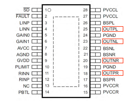
On this diagram of the pins it has L+,L-, R- then R+, just wanted to clarify which direction is correct?
This is what's on the back of the board.
But the circuit diagram makes it possible that the R pins might be wrongly marked?

EDIT: I can confirm that the board is marked wrongly.
The speakers are correctly in phase if you connect them L+ L- R- R+.

R1811-SpeakerPinout .jpg
 
Last edited:

LeMelleKH2

macrumors newbie
Dec 30, 2022
27
17
Hey everyone! I have one more question if it's no trouble. I am using a board to help increase the LED brightness, and am not sure if I should use a 24V 6A to account for the extra board, or if 24V 5A is sufficient?
 

PaulD-UK

macrumors 6502a
Oct 23, 2009
869
468
Are you going to use the R1811 board's 60 watt USB-C PD facility to charge a laptop?
If not then it will not need a full 5 amp supply.
 

LeMelleKH2

macrumors newbie
Dec 30, 2022
27
17
“To connect to the R1911 board maintaining the correct 4Ω impedance of the speaker units you could use a 10 microFarad capacitor in series with the tweeter, and a 0.32 milliHenry inductance (coil) in series with the woofer.
In practice you could forget about the inductance coil with no problems.”
Thanks Paul! I wont worry about the high current supply.

One other question about the speaker. So each speaker has an impedance of 4, correct? The tweeter is 4 ohms, and the woofer is 4 ohms?


LeMelleKH2

macrumors newbie
Dec 30, 2022
27
17
Hey all! Another question.

I want to retain the original power button function but have seen a few different ways to hook the cables to the control panel. I was wondering if I could get some clarity on the optimal way to accomplish this? Thanks!
 
  • Like
Reactions: •MacMike•

PaulD-UK

macrumors 6502a
Oct 23, 2009
869
468
So each speaker has an impedance of 4, correct? The tweeter is 4 ohms, and the woofer is 4 ohms?

Yes.

I want to retain the original power button function...

You need to extend the iMac's power button cable to connect to pins 3 (or 7) and 4 of the Control Strip cable.
Of course the iMac's power button will no longer turn off the new power supply you are using to power the R1811 board, so this will remain operational and connected to mains power.

Here's the pic (of the underside of the R1811) showing which wires/pins to connect to - K1 is the power switch.

ControlStripDetails.jpg
 
Last edited:

LeMelleKH2

macrumors newbie
Dec 30, 2022
27
17
So each speaker has an impedance of 4, correct? The tweeter is 4 ohms, and the woofer is 4 ohms?

Yes.

I want to retain the original power button function...

You need to extend the iMac's power button cable to connect to pins 3 (or 7) and 4 of the Control Strip cable.
Of course the iMac's power button will no longer turn off the new power supply you are using to power the R1811 board, so this will remain operational and connected to mains power.

Here's the pic (of the underside of the R1811) showing which wires/pins to connect to - K1 is the power switch.

View attachment 2138364
Thanks so much! So Im soldering to the panel, not the board itself. The diagram just happens to be on the board.

Thanks for the heads up on the supply! I was planning on having the panel still accessible
 
  • Like
Reactions: PaulD-UK

Chimney

macrumors newbie
Dec 24, 2022
2
0
Update to this message. When I hold up a lightmeter (well, a lightmeter app) to my screen (turned up to full brightness in the OSD), it is only reading 190 lux. While I know that number might not be accurate, for comparison, it is reading 320 lux on my old macbook pro from 2014. It seems like something isn't right? It doesn't seem that bright. I went for this vendor, with the constant current board: https://www.aliexpress.com/item/33014928363.html - its the same brown one pictured. Any thoughts?

Hi all, just done the mod with the U49, and it is mostly up and running well! but, when on a full white background, I see a purple tinge around all the edges which wasn't there before the mod. Anyone have any ideas what this is, and whether I can do anything about it? Thanks! View attachment 2132324
 
Last edited:

LeMelleKH2

macrumors newbie
Dec 30, 2022
27
17
Are you going to use the R1811 board's 60 watt USB-C PD facility to charge a laptop?
If not then it will not need a full 5 amp supply.
Sorry to bug Paul! One more question. I added the LEd backlight driver for my rig, and was wondering if you think 4A is still enough current for this and the controller or should I go with 5 in this case? The specs on the Driver board had current as 3.8 typically. Led Backlight Driver DZ-LP0818 Improving Brightness for LM270QQ1/LM270QQ2... | eBay
 

PaulD-UK

macrumors 6502a
Oct 23, 2009
869
468
Yes, if you turn up the backlight brightness with the add-on board there will be more power needed from your PSU.
Without better data on the R1811 board it is difficult to work out how much this well be - probably 5A or more is a better choice.
 

LeMelleKH2

macrumors newbie
Dec 30, 2022
27
17
Yes, if you turn up the backlight brightness with the add-on board there will be more power needed from your PSU.
Without better data on the R1811 board it is difficult to work out how much this well be - probably 5A or more is a better choice.
Thanks Paul! I couldnt find much on the info sheet I was sent, so Ill stick with my 5A for now!
 

LeMelleKH2

macrumors newbie
Dec 30, 2022
27
17
Yes, if you turn up the backlight brightness with the add-on board there will be more power needed from your PSU.
Without better data on the R1811 board it is difficult to work out how much this well be - probably 5A or more is a better choice.
I attached the file sheet here! I couldnt find anything but maybe I missed it.
 

Attachments

  • CY-R1811V3规格书0418(1).pdf
    854.7 KB · Views: 368

LeMelleKH2

macrumors newbie
Dec 30, 2022
27
17

You need to extend the iMac's power button cable to connect to pins 3 (or 7) and 4 of the Control Strip cable.
Of course the iMac's power button will no longer turn off the new power supply you are using to power the R1811 board, so this will remain operational and connected to mains power.

Here's the pic (of the underside of the R1811) showing which wires/pins to connect to - K1 is the power switch.
For the mac power cables, does it matter which one connects where?
 
Register on MacRumors! This sidebar will go away, and you'll see fewer ads.