Which model fan did you use and how did you replace the stock fan? Looks like it is embedded in the heat sink. Please post a pic if you got it!I have replaced the stock fan on mine with a slightly quieter Noctua fan. I don't use it for charging laptop so I wonder if I can get away with not having a fan at all.
Got a tip for us?
Let us know
Become a MacRumors Supporter for $50/year with no ads, ability to filter front page stories, and private forums.
DIY 5k Monitor - success :-)
- Thread starter fiatlux
- WikiPost WikiPost
- Start date
- Sort by reaction score
You are using an out of date browser. It may not display this or other websites correctly.
You should upgrade or use an alternative browser.
You should upgrade or use an alternative browser.
- Status
- The first post of this thread is a WikiPost and can be edited by anyone with the appropiate permissions. Your edits will be public.
I use the Noctua NF-A4x20 PWM. The 20mm height might be tight depending on where you mount the driver board in the iMac enclosure. You are better off getting the 10mm model as suggested by Borzab.Which model fan did you use and how did you replace the stock fan? Looks like it is embedded in the heat sink. Please post a pic if you got it!
I also use the Noctua Low Noise Adapter to lower the rpm of the fan so it runs slightly quieter. The noise is still audible but slightly better compared to the stock fan.
I had to trim the edge of the fan to make it "embedded" in the heat sink.
Yes it did after unscrewing all the screws. The fan is not glued to the heatsink.Thanks for the info! Did the stock fan simply come out after unscrewing the two screws? Not sure if it is glued in there and I don't want to find out the hard way.
Also did you need to cut and splice in the original stock fan's header?
I wanted a reversible solution so did not cut the wires of the stock fan. The final product looks pretty similar to Borzab's.
Me tooI wanted a reversible solution so did not cut the wires of the stock fan.
")
where did you buy the fan header?
I pushed the wires with the crimp still intact out from the plastic cover and connected new wires with crimp into the plastic cover. Not the best solution but I wanted to finish the project on the same day at that time.Me too
where did you buy the fan header?
I do not have the model/part number of the connector for the fan. It should not be too difficult to identify the make and model (for the speaker connector it is JST). You can get them from eBay.
The fan header looks identical to the JST XH series:


5 PAIRS JST XH 2.5-2 PIN Battery Connector Plug Female & Male- 125MM Fast Post | eBay UK
JST XH 2.5-2 Pin Male Connector Plug w/. Wire x 5 pcs. JST XH 2.5-2 Pin Female Connector Plug x 5 pcs,normally 1 extra plug free. -Cable Length : 125mm minimum. 5PLUGS WHICH ARE A MIXTURE IN COLOUR AS SHOWN AT RANDOM.
www.ebay.co.uk
10Pairs 10Sets XH2.54MM JST 2Pin Male to Female Plug Wire Connector 30cm Long | eBay
Find many great new & used options and get the best deals for 10Pairs 10Sets XH2.54MM JST 2Pin Male to Female Plug Wire Connector 30cm Long at the best online prices at eBay! Free delivery for many products!
www.ebay.co.uk
that looks like a perfect match, thanks! just ordered the Noctua NF-A4x10 PWM fan and header and will do some surgery in a few daysThe fan header looks identical to the JST XH series:
5 PAIRS JST XH 2.5-2 PIN Battery Connector Plug Female & Male- 125MM Fast Post | eBay UK
JST XH 2.5-2 Pin Male Connector Plug w/. Wire x 5 pcs. JST XH 2.5-2 Pin Female Connector Plug x 5 pcs,normally 1 extra plug free. -Cable Length : 125mm minimum. 5PLUGS WHICH ARE A MIXTURE IN COLOUR AS SHOWN AT RANDOM.www.ebay.co.uk10Pairs 10Sets XH2.54MM JST 2Pin Male to Female Plug Wire Connector 30cm Long | eBay
Find many great new & used options and get the best deals for 10Pairs 10Sets XH2.54MM JST 2Pin Male to Female Plug Wire Connector 30cm Long at the best online prices at eBay! Free delivery for many products!www.ebay.co.uk
I am assuming the audio connector is the one next to the fan connector. Any clue as to which pin is what (R/L +/-)?Thanks, I was able to connect the speaker wires and see what you mean--the amp on the R1811 board is very powerful!
Pinout of CSC3110 audio amplifier:I am assuming the audio connector is the one next to the fan connector. Any clue as to which pin is what (R/L +/-)?
The IC and connector are both located at the top right of the board. I can't be sure but I think the top 2 pins are left and bottom 2 pins are right. You can trace the circuit from the pins to the connector.
I am assuming the audio connector is the one next to the fan connector. Any clue as to which pin is what (R/L +/-)?
Yes I actually found that info in this same thread (the signal descriptions are from top to bottom):
All you have to do is to connect the wires of the speakers to the 4-pin header on the LCD driver board (Left+, Left-, Right+ and Right-) using the right connector.
I bought the connector from Amazon which only came as a pack of 20 so if you want send me your address and I’ll put some in an envelope for you.
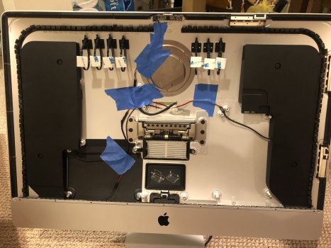
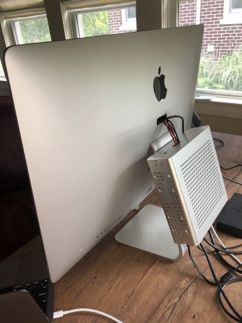
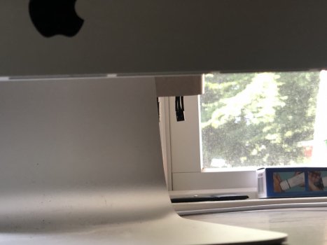
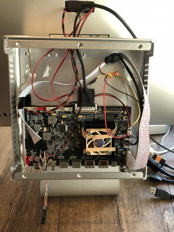
Well I've finally completed my build based on the R1811 LCD driver board. I followed the guidance in this thread and others but also put my own spin on it. I was concerned about installing every component in the iMac case including the driver board power supply. I thought heat build-up could be an issue with the power supply in the case. I have had similar power supplies fail in the past so I thought it's possible it may need to be replaced in a year or so. Lastly I wanted access to the driver board to easily plug in devices and also potentially upgrade the driver board in the future. I have no desire to open up the iMac again once it is sealed so mounting these externally was key.
The length of the LCD driver board cable was a determining factor. Based on its length, I realized I could mount the board externally, but not too far away. I came up with a plan to house the board in a small break-out box and attach it to the iMac stand. I found a mini-ATX case that matches the industrial metal look of the iMac and like how it turned out.
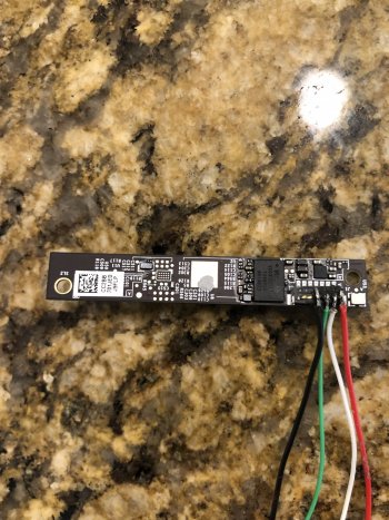
I planned to use the 5K monitor with my new Mac mini so a webcam was necessary. I hate the look of a webcam propped up on top of the monitor, so ideally I wanted to install a camera in the case similar to the iMac. I knew that the FaceTime camera from iMacs prior to 2012 as well as the Thunderbolt Display could be converted to USB; however, I found that space at the top of the thin iMac case was very challenging. This was the hardest part of the build for me. Ultimately I was able to disassemble a FaceTime camera board from a Thunderbolt Display to make it as small as possible, hook up a usb cable to it, and get it to fit (extremely snugly) within the iMac case. Overall I am very happy with the result.
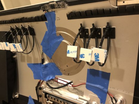
During my research I read about people replacing the LCD screens on iMacs, only to have them come apart and crash to the floor at some point. To address this, I installed a series of zip-ties with adhesive mounts to catch the LCD as emergency straps just in case it separated from the iMac case.
I also replaced the LCD driver board fan with the Noctua fan recommended by @Borzab to make it an almost silent device. I didn't like the PCB board supplied with the R1811, so I installed a new LED at the top of the case and a new IR receiver on the bottom of the case to receive signals from the included remote control.
While I had the opportunity, I also went ahead and replaced the original plastic hinge washers with metal ones I found eBay to preemptively address the infamous "broken hinge" problem plaguing some iMacs.
Thanks to everyone for posting their experiences in this thread—it has been a really fun and useful project!
Below are some pics of my build...
The length of the LCD driver board cable was a determining factor. Based on its length, I realized I could mount the board externally, but not too far away. I came up with a plan to house the board in a small break-out box and attach it to the iMac stand. I found a mini-ATX case that matches the industrial metal look of the iMac and like how it turned out.
I planned to use the 5K monitor with my new Mac mini so a webcam was necessary. I hate the look of a webcam propped up on top of the monitor, so ideally I wanted to install a camera in the case similar to the iMac. I knew that the FaceTime camera from iMacs prior to 2012 as well as the Thunderbolt Display could be converted to USB; however, I found that space at the top of the thin iMac case was very challenging. This was the hardest part of the build for me. Ultimately I was able to disassemble a FaceTime camera board from a Thunderbolt Display to make it as small as possible, hook up a usb cable to it, and get it to fit (extremely snugly) within the iMac case. Overall I am very happy with the result.
During my research I read about people replacing the LCD screens on iMacs, only to have them come apart and crash to the floor at some point. To address this, I installed a series of zip-ties with adhesive mounts to catch the LCD as emergency straps just in case it separated from the iMac case.
I also replaced the LCD driver board fan with the Noctua fan recommended by @Borzab to make it an almost silent device. I didn't like the PCB board supplied with the R1811, so I installed a new LED at the top of the case and a new IR receiver on the bottom of the case to receive signals from the included remote control.
While I had the opportunity, I also went ahead and replaced the original plastic hinge washers with metal ones I found eBay to preemptively address the infamous "broken hinge" problem plaguing some iMacs.
Thanks to everyone for posting their experiences in this thread—it has been a really fun and useful project!
Below are some pics of my build...
Attachments
Last edited:
In terms of software, the excellent Monitor Control app has an experimental branch which includes M1 support: https://github.com/MonitorControl/MonitorControl
I made one small change in ExternalDisplay.swift to reduce the maximum volume reported to the app to 35 (rather than the 100 returned by the R1811 driver board) since it is way too loud, and therefore the OSD slider of 16 steps wouldn't provide the appropriate level of granularity.
Now I can control the brightness and volume from my Mac keyboard
I made one small change in ExternalDisplay.swift to reduce the maximum volume reported to the app to 35 (rather than the 100 returned by the R1811 driver board) since it is way too loud, and therefore the OSD slider of 16 steps wouldn't provide the appropriate level of granularity.
Code:
  func getMaxValue(for command: DDC.Command) -> Int {

    //Adjust for maximum volume of 40 for R1811 LCD Driver board
    if (command.rawValue == 0x62) {
      return(35)
    }
    else {
    let max = self.prefs.integer(forKey: "max-\(command.rawValue)-\(self.identifier)")
    return min(self.DDC_HARD_MAX_LIMIT, max == 0 ? self.DDC_HARD_MAX_LIMIT : max)
    }
  }
Last edited:
Since my use-case requires connecting multiple computers to the 5K display (Mac mini, Dell laptop for work, and iPad Pro), I need a quick way to switch among each of them. I have a 4-way USB selector switch that easily lets me toggle one keyboard/mouse. I don't like using the included remote control to change the video input of the 5K monitor, so I wired the USB selector switch to my Raspberry Pi Zero and run a simply python script on it listening for which input button is pressed. It then runs "ddcutil" to tell the monitor to switch to a specific input. The Pi needs to be connected to the monitor through its HDMI port to communicate with the monitor. I've figured out the following inputs:
0x10 -> USB-C input
0x11 -> DP1 input
0x12 -> DP2 input
Unfortunately there doesn't seem to be a way to programmatically switch to either of the two HDMI inputs.
Anyway this works for me--I press one button on the USB selector and it automatically switches the video input to the correct source as well as the keyboard and mouse
If there's a DDC command to set the input, then shouldn't there be a DDC command to get the current input?Since my use-case requires connecting multiple computers to the 5K display (Mac mini, Dell laptop for work, and iPad Pro), I need a quick way to switch among each of them. I have a 4-way USB selector switch that easily lets me toggle one keyboard/mouse. I don't like using the included remote control to change the video input of the 5K monitor, so I wired the USB selector switch to my Raspberry Pi Zero and run a simply python script on it listening for which input button is pressed. It then runs "ddcutil" to tell the monitor to switch to a specific input. The Pi needs to be connected to the monitor through its HDMI port to communicate with the monitor. I've figured out the following inputs:
0x10 -> USB-C input
0x11 -> DP1 input
0x12 -> DP2 input
Unfortunately there doesn't seem to be a way to programmatically switch to either of the two HDMI inputs.
Anyway this works for me--I press one button on the USB selector and it automatically switches the video input to the correct source as well as the keyboard and mouse
https://www.nirsoft.net/articles/set_monitor_input_source_command_line.html
Thanks for the suggestion, but unfortunately the board doesn't report accurate info via ddcutil. The board has the following inputs:If there's a DDC command to set the input, then shouldn't there be a DDC command to get the current input?
https://www.nirsoft.net/articles/set_monitor_input_source_command_line.html
USB-C
DisplayPort 1
DisplayPort 2
HDMI-1
HDMI-2
Using 'ddcutil capabilities', it reports:
Feature: 60 (Input Source)
Values:
01: VGA-1
03: DVI-1
04: DVI-2
0f: DisplayPort-1
10: DisplayPort-2
11: HDMI-1
12: HDMI-2
I also tried switching to each input using the remote control and running 'ddcutil getvcp known', and this gave the following:
switching to USB-C via remote control -> 'ddcutil getvcp 60' returns DisplayPort-1 (sl=0x0f)
switching to DisplayPort 1 via remote control -> 'ddcutil getvcp 60' returns DisplayPort-2 (sl=0x10)
switching to DisplayPort 1 via remote control -> 'ddcutil getvcp 60' returns DisplayPort-1 (sl=0x0f)
switching to HDMI-1 via remote control -> 'ddcutil getvcp 60' returns HDMI-1 (sl=0x11)
switching to HDMI-2 via remote control -> 'ddcutil getvcp 60' returns HDMI-2 (sl=0x12)
Based on this inconsistent data, I can only reliably do the following:
'ddcutil setvcp 60 0x0f' -> switches the input to USB-C
'ddcutil setvcp 60 0x11' -> switches the input to DisplayPort-1
'ddcutil setvcp 60 0x12' -> switches the input to DisplayPort-2
Nice build and thanks for sharing.Well I've finally completed my build based on the R1811 LCD driver board. I followed the guidance in this thread and others but also put my own spin on it. I was concerned about installing every component in the iMac case including the driver board power supply. I thought heat build-up could be an issue with the power supply in the case. I have had similar power supplies fail in the past so I thought it's possible it may need to be replaced in a year or so. Lastly I wanted access to the driver board to easily plug in devices and also potentially upgrade the driver board in the future. I have no desire to open up the iMac again once it is sealed so mounting these externally was key.
The length of the LCD driver board cable was a determining factor. Based on its length, I realized I could mount the board externally, but not too far away. I came up with a plan to house the board in a small break-out box and attach it to the iMac stand. I found a mini-ATX case that matches the industrial metal look of the iMac and like how it turned out.
I planned to use the 5K monitor with my new Mac mini so a webcam was necessary. I hate the look of a webcam propped up on top of the monitor, so ideally I wanted to install a camera in the case similar to the iMac. I knew that the FaceTime camera from iMacs prior to 2012 as well as the Thunderbolt Display could be converted to USB; however, I found that space at the top of the thin iMac case was very challenging. This was the hardest part of the build for me. Ultimately I was able to disassemble a FaceTime camera board from a Thunderbolt Display to make it as small as possible, hook up a usb cable to it, and get it to fit (extremely snugly) within the iMac case. Overall I am very happy with the result.
During my research I read about people replacing the LCD screens on iMacs, only to have them come apart and crash to the floor at some point. To address this, I installed a series of zip-ties with adhesive mounts to catch the LCD as emergency straps just in case it separated from the iMac case.
I also replaced the LCD driver board fan with the Noctua fan recommended by @Borzab to make it an almost silent device. I didn't like the PCB board supplied with the R1811, so I installed a new LED at the top of the case and a new IR receiver on the bottom of the case to receive signals from the included remote control.
While I had the opportunity, I also went ahead and replaced the original plastic hinge washers with metal ones I found eBay to preemptively address the infamous "broken hinge" problem plaguing some iMacs.
Thanks to everyone for posting their experiences in this thread—it has been a really fun and useful project!
Below are some pics of my build...
What is your experience with adjusting volume using DDC/CI? Does it work all the time? Mine seems to work only half of the time.In terms of software, the excellent Monitor Control app has an experimental branch which includes M1 support: https://github.com/MonitorControl/MonitorControl
I made one small change in ExternalDisplay.swift to reduce the maximum volume reported to the app to 35 (rather than the 100 returned by the R1811 driver board) since it is way too loud, and therefore the OSD slider of 16 steps wouldn't provide the appropriate level of granularity.
Now I can control the brightness and volume from my Mac keyboardCode:func getMaxValue(for command: DDC.Command) -> Int { //Adjust for maximum volume of 40 for R1811 LCD Driver board if (command.rawValue == 0x62) { return(35) } else { let max = self.prefs.integer(forKey: "max-\(command.rawValue)-\(self.identifier)") return min(self.DDC_HARD_MAX_LIMIT, max == 0 ? self.DDC_HARD_MAX_LIMIT : max) } }
I cannot get it to switch to HDMI too.Thanks for the suggestion, but unfortunately the board doesn't report accurate info via ddcutil. The board has the following inputs:
USB-C
DisplayPort 1
DisplayPort 2
HDMI-1
HDMI-2
Using 'ddcutil capabilities', it reports:
Feature: 60 (Input Source)
Values:
01: VGA-1
03: DVI-1
04: DVI-2
0f: DisplayPort-1
10: DisplayPort-2
11: HDMI-1
12: HDMI-2
I also tried switching to each input using the remote control and running 'ddcutil getvcp known', and this gave the following:
switching to USB-C via remote control -> 'ddcutil getvcp 60' returns DisplayPort-1 (sl=0x0f)
switching to DisplayPort 1 via remote control -> 'ddcutil getvcp 60' returns DisplayPort-2 (sl=0x10)
switching to DisplayPort 1 via remote control -> 'ddcutil getvcp 60' returns DisplayPort-1 (sl=0x0f)
switching to HDMI-1 via remote control -> 'ddcutil getvcp 60' returns HDMI-1 (sl=0x11)
switching to HDMI-2 via remote control -> 'ddcutil getvcp 60' returns HDMI-2 (sl=0x12)
Based on this inconsistent data, I can only reliably do the following:
'ddcutil setvcp 60 0x0f' -> switches the input to USB-C
'ddcutil setvcp 60 0x11' -> switches the input to DisplayPort-1
'ddcutil setvcp 60 0x12' -> switches the input to DisplayPort-2
I have the same issue, for both volume and brightness control. It seems that when my Mac comes out of sleep, sometimes the app gets hung up and needs to be quit and then restarted. However I recently made the below change and so far it has been working reliably:What is your experience with adjusting volume using DDC/CI? Does it work all the time? Mine seems to work only half of the time.
Last edited:
Still experiencing this issue. I see that it was reported and a temp/debug build has been submitted for review which addresses it: https://github.com/MonitorControl/MonitorControl/issues/530I have the same issue, for both volume and brightness control. It seems that when my Mac comes out of sleep, sometimes the app gets hung up and needs to be quit and then restarted. However I recently made the below change and so far it has been working reliably:
View attachment 1825255
I'm testing out the build right now and will report back...
This thread is amazing and the people here doing the builds are very talented. But, FFS Apple, do you see the lengths people are going to for a hi PPI monitor? Just make one already! LG discontinued there’s and the XDR is not justifiable for most people.
I am in the middle of a 2 part process build, and I’m in the hardware mounting stage and testing stage.
I purchased the r1811 board and I’m interested in building an EGPU “into” the case (of course with lots of chassis modification.)
A few of the things I tested:
Before I start on everything though, I do have a bit of a problem:
The display is quite dark especially in comparison to the original iMac display. I can increase the brightness to get about 2/3 as bright but it washes out all greys/blacks and colors to the point it looks rediculous. I saw there was a firmware update? Could that potentially help?
How did it perform? Anything to watch out for?
Thanks!


I purchased the r1811 board and I’m interested in building an EGPU “into” the case (of course with lots of chassis modification.)
A few of the things I tested:
1. I wanted to build into the case a SuperDrive for DVD/CD reading and writing. I tested it plugged into the board as well as plugged into a powered Dell dock and it wouldn’t work within either. I’m curious if there is a python/JS C++ or Swift workaround since it seems like it’s a software related feature block and it would be cool to have a 2019 iMac dual display with a CD Drive lol. (Maybe it’s just me).
2. I do have a hardly used 1TB SSD out of my 2011 MBA that I purchased a usb 2.1 case for. The r1811 powered it easily and my iMac sees it without fuss via a single HDMI port (my OWC 5K display port adapter still hasn’t come in yet.
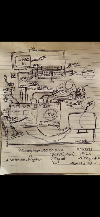
3. The second part of the project is building an EGPU with a w5500 or a w6600 connected to an ADT-Link and a HDPLEX 800 watt PSU. I included my planned layout pictures.
Before I start on everything though, I do have a bit of a problem:
The display is quite dark especially in comparison to the original iMac display. I can increase the brightness to get about 2/3 as bright but it washes out all greys/blacks and colors to the point it looks rediculous. I saw there was a firmware update? Could that potentially help?
How did it perform? Anything to watch out for?
Thanks!
Attachments
Tbh I haven’t noticed any issue and it seems bright enough…where did you see a firmware update?Anyone’s Backlight only about 1/2- 2/3 the brightness of the original screen on the R1811?
Last edited:
The USB 2.0 ports are not powered so you would need a powered hub for the SuperDrive. Also the USB-C port will only give you video (DP over USB-C) plus expose the USB 2.0 ports, meaning you can’t connect a storage device to it.Anything to watch out for?
Last edited:
So I plugged a dell wall-powered dock into a Thunderbolt 3 port and plugged the SuperDrive into a USB 2.0 or 2.1 port (blue) and it seems like Mac OS still wants it directly plugged in. Have you personally had any luck?The USB 2.0 ports are not powered so you would need a powered hub for the SuperDrive. Also the USB-C port will only give you video (DP over USB-C) plus expose the USB 2.0 ports, meaning you can’t connect a storage device to it.
Also, as you meantioned above, I’ve been pondering about how that whole egpu wouldn’t receive audio and the cost and complexity has really just made me think about just keeping things simple... running some audio and being done with it.
I did think however, with the NVME port (which typically houses the operating system on the iMac)
What would be the downsides of (and has anyone tested if Max OS supports):
if you plugged the EGPU adaptor straight into the iMac’s NVME port. You should get double the Read/write speeds of compared to a thunderbolt 3 port, connect the egpu to the R1811 via the dual display port for 5K.
I’m assuming that if I plugged in my 2TB Samsung Evo encased in a USB 2.0 port and connect it to the R1811, would the graphics card only pass through video data and not read write data or do you think that might also be supported?
I would personally test this (even though I’d rather not open up my iMac again, but I don’t have a Graphics card to test yet.
Register on MacRumors! This sidebar will go away, and you'll see fewer ads.