Become a MacRumors Supporter for $50/year with no ads, ability to filter front page stories, and private forums.
Status
The first post of this thread is a WikiPost and can be edited by anyone with the appropiate permissions. Your edits will be public.

BeatCrazy

macrumors 603
Jul 20, 2011
5,139
4,517
The adaptor supply power from the PCI-E socket to both WiFi and BT sections; if you do not need to control them separately, this works perfectly.

What about connecting/hacking the D+/D-/3.3V lines? Is messing with those only needed if you want to separately control the BT vs. Wi-Fi power?
 

dac610

macrumors member
Mar 26, 2020
59
13
You must connect D+/D- which are USB data lines for the BT section.

USB 3.3V power supply is only needed if you want individual on/off control for BT and WiFi sections. In that case you need to cut a trace on the adapter that connects the 2 supply lines.
 

Ausdauersportler

macrumors 603
Nov 25, 2019
5,007
5,826
We have a first post and page 1 here to and guide linked from there which should answer really every single question you might have.

I just put together all the strings from this thread in this guide and added the BCM942602CDP story about potential Apple Watch unlock with Catalina.

You might also read through this thread, it is not so log an you get quickly an overview about components and methods. I would recommend to use the old BT cable and get the needed lines from there.
 

BeatCrazy

macrumors 603
Jul 20, 2011
5,139
4,517
You must connect D+/D- which are USB data lines for the BT section.

USB 3.3V power supply is only needed if you want individual on/off control for BT and WiFi sections. In that case you need to cut a trace on the adapter that connects the 2 supply lines.

The R1 on the PCI-E adapter has 2 pads. I've seen some pictures where the wire is only connected to one of the pads. Ar you saying that I should bridge the 2 pads for the 3.3V wire?
minipcie-soldered-wifi-jpg.949643.jpg
 

BeatCrazy

macrumors 603
Jul 20, 2011
5,139
4,517
We have a first post and page 1 here to and guide linked from there which should answer really every single question you might have.

I just put together all the strings from this thread in this guide and added the BCM942602CDP story about potential Apple Watch unlock with Catalina.


I do appreciate your guidance on this (and other threads). I have read this entire thread at least 3 times :) The R1 pad connection has conflicting responses.

Per your suggestion, I definitely want to have the "what can I do for this thread" approach - which is why I took a chance with the BCM942602CDP, and will give guidance regarding this new V4 PCI-E adapter and how to correctly fit the BCM942602CDP to the standoff.
 

dac610

macrumors member
Mar 26, 2020
59
13
See diagrams at post #75.
First check continuity between pins P1 and P18 on the adapter connector for the card. If there is, you do not need additional 3.3V supply.

If you desire separate control, you have to cut somewhere the trace that connect the 2 pins AND use additional 3.3V line to go to P18.
 
  • Like
Reactions: BeatCrazy

Ausdauersportler

macrumors 603
Nov 25, 2019
5,007
5,826
I do appreciate your guidance on this (and other threads). I have read this entire thread at least 3 times :) The R1 pad connection has conflicting responses.

Per your suggestion, I definitely want to have the "what can I do for this thread" approach - which is why I took a chance with the BCM942602CDP, and will give guidance regarding this new V4 PCI-E adapter and how to correctly fit the BCM942602CDP to the standoff.
My guide has no such conflicting responses. I do not discuss facts! But I always like to find errors in all (my) posts made and will correct these happily.

Since all adapter cards are slightly different I use a multimeter to find the fitting solder points which connects to both outer pins of the new replacement cards. There the 3.3V has to be connected to.

Usually I solder directly to the left pin. I have installed three of these BCM943602CDP cards, they fit with every adapter card I used.
 
Last edited:

Allistah

macrumors 6502
Apr 19, 2019
254
80
Bay Area, CA
I have a 2011 27” iMac. Model #: A1312, EMC #: 2429.

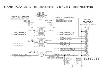
Here is the pinout of the connector that is right next to the PCI-E slot where we are plugging these adapter boards into. Instead of running cables all the way over to where the old usb board is, couldn’t we just get it all here?

I’d be interested in pins 8,9, and 10 counting from the right side. I think pin 1 is on the right side. On the schematic, the USB_BT_L_N and USB_BT_L_P are the D- and D+ lines where N means negative and P means positive. The pinouts in the schematic matches to the colors where D- is pink, D+ is white, and orange/red is the 3.3v.

F1EEE13E-5587-429B-9C97-02F66EA3B7CE.jpeg


Screen Shot 2020-10-20 at 9.55.21 PM.png
 

Attachments

  • 65FE1BA0-C72A-40D0-988B-D554F8DB4EDE.jpeg
    65FE1BA0-C72A-40D0-988B-D554F8DB4EDE.jpeg
    143.2 KB · Views: 291
Last edited:

Ausdauersportler

macrumors 603
Nov 25, 2019
5,007
5,826
Yes, you can also reroute the BT cable back to the wifi port. But you still need to the BT antenna cable to go the long way. Where is the gain? Of course you can route the antenna cable the same way the BT cable took before. Then you have no loose cables running through the system.
 

Allistah

macrumors 6502
Apr 19, 2019
254
80
Bay Area, CA
True in regard to getting the BT antenna cable all the way over there. Was just pointing out that getting the D-, D+. and 3.3v was able to be done locally to the WiFi card if people didn't have long cables/wires.
 
  • Like
Reactions: Ausdauersportler

Allistah

macrumors 6502
Apr 19, 2019
254
80
Bay Area, CA
I ended up buying a spare bluetooth board that I could desolder the connector from to use to attach the D-, D+, and 3.3v lines to. Figured it would be safer than compromising the cable or trying to solder to the motherboard. If something goes wrong, it's an expensive fix. For $10, it was worth it to get the little board for the connector. Hope to get everything soon so I can do the upgrade.
 
  • Like
Reactions: Ausdauersportler

Allistah

macrumors 6502
Apr 19, 2019
254
80
Bay Area, CA
Looks like my WiFi/BT module is showing up here within hours. I prepared the adapter board for it, cut the trace, and soldered a line for the BT 3.3v. You can see where I cut the trace at the bottom of the E in the text VER. I’ll use the plug for the D+ and D-. Will report back when I’m done.

UPDATE: The adapter below will not work with a Apple 653-00011 Broadcom BCM943602CDP WiFi Bluetooth Airport Card. That white connector on the right side interferes with the module laying into place.

I tried to remove it but I don't have the right tools to remove things that small with multiple anchor points and I ended up trashing the adapter board. Ordered another, different one that will let me wonder the D+ and D- lines to the left side of the board.

700B79BE-4C6B-474E-BF65-5FDF6ADDB7D7.jpeg
 
Last edited:

BeatCrazy

macrumors 603
Jul 20, 2011
5,139
4,517
UPDATE: The adapter below will not work with a Apple 653-00011 Broadcom BCM943602CDP WiFi Bluetooth Airport Card. That white connector on the right side interferes with the module laying into place.

I tried to remove it but I don't have the right tools to remove things that small with multiple anchor points and I ended up trashing the adapter board. Ordered another, different one that will let me wonder the D+ and D- lines to the left side of the board.

EDIT - sorry I realize after I posted that it's the D+/D- connector that interferes, not the wire soldered to the R1 pad.

Maybe I will try to cut/break off that white connector without trashing the board. Which replacement did you order?

Also, why did you cut the trace?
 
Last edited:

Allistah

macrumors 6502
Apr 19, 2019
254
80
Bay Area, CA
Ugh. My card won't arrive for two more days... How about soldering to that R1 pad "below" the card? Meaning the bottom, or the other side of the adapter card.

Yeah what a letdown. I mangled the card and I'm afraid to try and use it again in case there is a short somewhere on it. Not worth the risk. I ordered a new one. It will be here tomorrow - gotta love Prime and one day deliveries. This is the one I have coming. It'll allow me to attach the D+ and D- wires much easier and they'll have a strong hold in those holes. I'll attach the 3.3v line to the R1 pad when I take a closer look at the traces to see where I need to cut the trace to separate the power. Will update tomorrow.

Screen Shot 2020-10-21 at 4.27.24 PM.png
 

BeatCrazy

macrumors 603
Jul 20, 2011
5,139
4,517
Yeah what a letdown. I mangled the card and I'm afraid to try and use it again in case there is a short somewhere on it. Not worth the risk. I ordered a new one. It will be here tomorrow - gotta love Prime and one day deliveries. This is the one I have coming. It'll allow me to attach the D+ and D- wires much easier and they'll have a strong hold in those holes. I'll attach the 3.3v line to the R1 pad when I take a closer look at the traces to see where I need to cut the trace to separate the power. Will update tomorrow.

View attachment 970737
Thanks, I'll order that one as well and send back my original. But I don't understand why you need to cut the trace?

And it doesn't look like there will be anyway to use a standoff/mount from the BCM943602CDP to that newer adapter card you just ordered? I guess I could use use electrical tap, wrapped, to keep it on the adapter?
 
Last edited:

Allistah

macrumors 6502
Apr 19, 2019
254
80
Bay Area, CA
Thanks, I'll order that one as well and send back my original. But I don't understand why you need to cut the trace?

And it doesn't look like there will be anyway to use a standoff/mount from the BCM943602CDP to that newer adapter card you just ordered? I guess I could use use electrical tap, wrapped, to keep it on the adapter?

Well, from what I understand, the mini PCI-E port on the 2011 27" iMac turns off all the power to that card when you turn off Wifi because BT and WIFI are separate and have separate power lines by default. Since we're installing a newer card that contains wifi and BT together, BT would get cut off too when we turned off the Wifi since they're on the same card. To solve this, you cut a trace on the adapter board that supplies the BT part power and solder a wire from the old BT 3.3v connection to it. That way when you disable wifi, the BT portion of the card still has power and operates. It also works the other way, when you cut the trace on the board and have the BT 3.3v on there, you could turn off BT and it would cut only the BT power and the Wifi would still operate. It just allows you to turn wifi and BT on/off independent of each other. Hope that makes sense?

What kind of a Mac are you installing yours in? I'm installing the BCM943602CDP board in hopes that I can unlock my Mac with my Apple Watch cause I'm lazy like that. lol

One last thing.. I think that new adapter board I'm getting tomorrow will line up with the board I'm installing. The first adapter board I bought came with screws so I'll use those to screw it in. I compared them just by eye before I bought it and I think it'll work. Will see tomorrow.. I'll post some pics.
 

BeatCrazy

macrumors 603
Jul 20, 2011
5,139
4,517
Well, from what I understand, the mini PCI-E port on the 2011 27" iMac turns off all the power to that card when you turn off Wifi because BT and WIFI are separate and have separate power lines by default. Since we're installing a newer card that contains wifi and BT together, BT would get cut off too when we turned off the Wifi since they're on the same card. To solve this, you cut a trace on the adapter board that supplies the BT part power and solder a wire from the old BT 3.3v connection to it. That way when you disable wifi, the BT portion of the card still has power and operates. It also works the other way, when you cut the trace on the board and have the BT 3.3v on there, you could turn off BT and it would cut only the BT power and the Wifi would still operate. It just allows you to turn wifi and BT on/off independent of each other. Hope that makes sense?

What kind of a Mac are you installing yours in? I'm installing the BCM943602CDP board in hopes that I can unlock my Mac with my Apple Watch cause I'm lazy like that. lol

One last thing.. I think that new adapter board I'm getting tomorrow will line up with the board I'm installing. The first adapter board I bought came with screws so I'll use those to screw it in. I compared them just by eye before I bought it and I think it'll work. Will see tomorrow.. I'll post some pics.

Yes, I think I understand what we're trying to accomplish via the 3.3V wire, but I think (!) if you cut the trace, you're defeating the purpose. The 3.3V from the BT logic board connection will have no way to reach the new card, if you cut the trace.

I plan on leaving BT and Wi-Fi on all the time, but I understand what you're trying to do.
 

Allistah

macrumors 6502
Apr 19, 2019
254
80
Bay Area, CA
Yes, I think I understand what we're trying to accomplish via the 3.3V wire, but I think (!) if you cut the trace, you're defeating the purpose. The 3.3V from the BT logic board connection will have no way to reach the new card, if you cut the trace.

I plan on leaving BT and Wi-Fi on all the time, but I understand what you're trying to do.

If you did no cutting like your’re doing, if you turned off WiFi, BT and WiFi will turn off together. All I’m doing is isolating the power for each side and bringing over power from the original BT module. You can’t just cut the trace.. you have to bring over power from the old usb board. If you didn’t do that, you’re right, the BT portion of the board wouldn’t work if you cut the trace and did nothing else.

Searching this thread, that’s what other people have done so they could turn each part on and off independently of each other. Since I’m getting the adapter tomorrow, I’m hoping I’ll have some time to install this thing properly without jacking up the board. Lol
 

BeatCrazy

macrumors 603
Jul 20, 2011
5,139
4,517
If you did no cutting like your’re doing, if you turned off WiFi, BT and WiFi will turn off together. All I’m doing is isolating the power for each side and bringing over power from the original BT module. You can’t just cut the trace.. you have to bring over power from the old usb board. If you didn’t do that, you’re right, the BT portion of the board wouldn’t work if you cut the trace and did nothing else.

Searching this thread, that’s what other people have done so they could turn each part on and off independently of each other. Since I’m getting the adapter tomorrow, I’m hoping I’ll have some time to install this thing properly without jacking up the board. Lol

Yes, I plan on bringing the 3.3V power over from the logic board. But I thought cutting the trace would cut off the 3.3V power from the R1 pad to P18 on the adapter. Unless I'm confused about which trace you're cutting? The R1 pad (the one closest to the card) goes to the P18 on the adapter, I measured mine.

Interestingly, my BT card arrived late today and the P/N is slightly different: BCM943602CDPAX_2. Not sure if that is any tangible difference from _1. Same APN.

As soon as my "new" adapter arrives tomorrow from Amazon, I'll be trying the same thing as you, but without cutting the trace :)
 

BeatCrazy

macrumors 603
Jul 20, 2011
5,139
4,517
One last thing.. I think that new adapter board I'm getting tomorrow will line up with the board I'm installing. The first adapter board I bought came with screws so I'll use those to screw it in. I compared them just by eye before I bought it and I think it'll work. Will see tomorrow.. I'll post some pics.

The screws from that first/original adapter board (M2 and/or M1.4) don't appear to fit in the threads for the BCM943602CDP. At least the one I have. Seems like it needs an M1.6 or M1.8, if such a screw exists.
 

Allistah

macrumors 6502
Apr 19, 2019
254
80
Bay Area, CA
Yes, I plan on bringing the 3.3V power over from the logic board. But I thought cutting the trace would cut off the 3.3V power from the R1 pad to P18 on the adapter. Unless I'm confused about which trace you're cutting? The R1 pad (the one closest to the card) goes to the P18 on the adapter, I measured mine.

Interestingly, my BT card arrived late today and the P/N is slightly different: BCM943602CDPAX_2. Not sure if that is any tangible difference.

As soon as my "new" adapter arrives tomorrow from Amazon, I'll be trying the same thing as you, but without cutting the trace :)

When you cut the trace, it has to be between pin 1 and pin 18, leaving the R1 pad --> Pin 18 intact. Its just to separate pin 1 and pin 18.
 

BeatCrazy

macrumors 603
Jul 20, 2011
5,139
4,517
When you cut the trace, it has to be between pin 1 and pin 18, leaving the R1 pad --> Pin 18 intact. Its just to separate pin 1 and pin 18.

Ahhhhh. Critical info! :D What did you use to cut it? I'm so clumsy, I'm afraid of mucking up the entire board.
 

Ausdauersportler

macrumors 603
Nov 25, 2019
5,007
5,826
If both of you just want to chat, please use a PM.

Both outer PINs can be connected to the 3.3V according to the wiring diagram somewhere here. One connection is sufficient.

There is absolutely no need to cut a trace on the board. You are the first claiming this without having a single running installation. Really great!!

You are spreading out more doubt and myst than information, sorry.
 

Allistah

macrumors 6502
Apr 19, 2019
254
80
Bay Area, CA
The new adapter board will be arriving today. The plan is to use a 3 conductor ribbon cable from something else, I will just pull off 3 strands. Two will go to the D+ and D- connections, and the other will go to the 3.3v from the old BT board. I'll have to make some decisions once I get the adapter board and see how the two boards come together and how much room I have. Here is a pic of the ribbon cable that I will pull 3 conductors off for this upgrade:

542F8FBF-A5B5-4BF5-9BC5-8E3B57609BA1.jpeg
 
Last edited:

Allistah

macrumors 6502
Apr 19, 2019
254
80
Bay Area, CA
Got everything installed. During the boot process, I get the Apple logo and the loading bar. Then half way through progress/boot loading bar the screen goes blank and then that's it. I'm wondering if I should disconnect the 3.3v from the BT module to the board..

Any other ideas what is wrong? Since the BT changed, is it hanging up on no keyboard/mouse or something?

Update: I pulled the machine apart and removed the 3.3v line to the adapter board on R1. Now the machine boots. Of course there is no BT, but Wifi is working fine. Here is the data it is showing for the WiFi:

Card Type: AirPort Extreme (0x14E4, 0x16D)
Firmware Version: Broadcom BCM43xx 1.0 (7.77.61.3 AirPortDriverBrcmNIC-1305.10)
Supported PHY Modes: 802.11 a/b/g/n/ac

I'm wondering if the adapter board I have is not the right one or something. Maybe I connected the 3.3v to the wrong spot maybe, but I'm pretty sure I connected it to the place where it connects to pin 18. Maybe I should double check that.

If anyone else has any ideas, would love to hear them.

Update #2: I made sure that the 3.3v was connected to the right place and that it goes to pin 18. While I had the system booted, I turned BT off. Now that I connected the 3.3v line again, the system booted since BT was still off.

Once the system was booted, I turned BT on. In BT Explorer, I got these messages:

Process: Bluetooth Explorer 6.0.9
Operating System: Version 10.14.6 (Build 18G6020)
Date: 2020-10-23 04:53:45 +0000

Initializing Bluetooth...
BluetoothHCIReadLocalVersionInformation failed; 0xE00002D7.
Bluetooth Support Initialization complete.

Oct 22 21:54:26 Hackintosh com.apple.xpc.launchd[1] (com.apple.imfoundation.IMRemoteURLConnectionAgent): Unknown key for integer: _DirtyJetsamMemoryLimit
Oct 22 21:54:29 --- last message repeated 1 time ---
Oct 22 21:54:29 Hackintosh com.apple.xpc.launchd[1] (com.apple.bluetoothd[93]): Service exited due to SIGABRT
Oct 22 21:54:29 Hackintosh com.apple.xpc.launchd[1] (com.apple.imfoundation.IMRemoteURLConnectionAgent): Unknown key for integer: _DirtyJetsamMemoryLimit

Bluetooth Module powered on.

(null) (Handle: 0xC) connection failed, status: 0x04
-------

I'm starting to think that this adapter board is the wrong one or something.
 
Last edited:
Register on MacRumors! This sidebar will go away, and you'll see fewer ads.