Become a MacRumors Supporter for $50/year with no ads, ability to filter front page stories, and private forums.
"h9826790" I always strive to learn a bit along the way but if it's too complicated to explain:

"Why the power load will be more evenly distributed with the "bridge method"

Maybe you could post me a link for some kind of explanation? :)

It's actually simply Physics.

By using a bridge, both 6+8 pin is connected to the same source (the bridge), and the bridge is connected to BOTH mini 6pins.

There are three 12V line inside the bridge, but you may consider there is only a single line for this purpose.

So, when all demand flow through a bridge, and the bridge connected to multiple source (mini 6pin). The electricity will flow from the higher voltage source to the bridge AND the lower voltage source. However, in this case, both sources are 12V. Therefore, ideally, there will be no electricity flow from one source to the other.

Now, lets look a little bit deeper.

e.g. On the GPU side, 6pin demand 4A and 8pin demand 6A.

Then all 10A will flow through the bridge. In the GPU's point of view. There is a single 10A power source.

And this 10A must be coming from both mini 6pin.

Since on the mini 6pins point of view. There is only one single 10A demand. Therefore, each mini 6pin will supply 5A to the bridge (assuming the resistance in the circuit is evenly distributed).

You may consider it just simply follow the V=IR rule (ohm's law).

Same V, same R, will lead to the same I on each mini 6pin. Therefore, each mini 6pin only need to supply half of the demand from the bridge. End up the power load is pretty much evenly distributed between them.

Arhh okay I see :)

Last question before I buy the female 8-pin --> 2*6+2 pin cable...

Maybe I'm a bit confused but what are the advantages when using the:

1) EVGA powerlink

2) The cable you linked yourself

https://www.btosinte.com/Seasonic-8...Cable-w-inline-capacitor-SS-IN-8-2x62PCIe.htm

???
 
Last edited:
Arhh okay I see :)

Last question before I buy the female 8-pin --> 2*6+2 pin cable...

Maybe I'm a bit confused but what are the advantages when using the:

1) EVGA powerlink

2) The cable you linked yourself

https://www.btosinte.com/Seasonic-8...Cable-w-inline-capacitor-SS-IN-8-2x62PCIe.htm

???

EVGA power link should be better, because the build in capacitors provide power conditioning. This may be the key why some high TDP GPU (e.g. 1080Ti) can run CUDA-Z heavy test without shutdown. However, more expensive and not all GPU can use. e.g. There is no room for my 1080Ti to use EVGA powerlink.
Just fit.jpg


Combination of cables is cheaper. Should work on all graphic cards, but no power conditioning.
 
  • Like
Reactions: Reindeer_Games
EVGA power link should be better, because the build in capacitors provide power conditioning. This may be the key why some high TDP GPU (e.g. 1080Ti) can run CUDA-Z heavy test without shutdown. However, more expensive and not all GPU can use. e.g. There is no room for my 1080Ti to use EVGA powerlink.
just-fit-jpg.760318


Combination of cables is cheaper. Should work on all graphic cards, but no power conditioning.

Yup that's making sense. The powerlink is not that expensive for me to buy but my GTX 970 is only 2mm shorter than your 1080 TI so no way in hell that will fit together with the powerlink in the Mac Pro :)

I will go ahead and order this female 8-pin --> 2*(6+2)-pin cable:

https://www.ebay.com/itm/1-Pc-PCIE-8p-Female-to-2-Port-Dual-8pin-6-2p-Male-GPU-Graphics-Power-Cable-18AWG/282891957530?ssPageName=STRK:MEBIDX:IT&_trksid=p2055119.m1438.l2649

and cross fingers!
 
Last edited:
Yup that's making sense. The powerlink is not that expensive for me to buy but my GTX 970 is only 2mm shorter than your 1080 TI so no way in hell that will fit together with the powerlink in the Mac Pro :)

I will go ahead and order this female 8-pin --> 2*(6+2)-pin cable:

https://www.ebay.com/itm/1-Pc-PCIE-8p-Female-to-2-Port-Dual-8pin-6-2p-Male-GPU-Graphics-Power-Cable-18AWG/282891957530?ssPageName=STRK:MEBIDX:IT&_trksid=p2055119.m1438.l2649

and cross fingers!

My 1080Ti is the PNY XLR8 model (link in my signature), it's way longer than the FE. I don't think a 970 need a heat sink in that size.
 
My 1080Ti is the PNY XLR8 model (link in my signature), it's way longer than the FE. I don't think a 970 need a heat sink in that size.

I know your card (read that post about it before...) - It's this one right?:

http://www.pny.com/geforce-gtx-1080ti-xlr8gaming-oc

If so, that card is 314 mm long and my card is 299 mm.

https://www.gigabyte.com/Graphics-Card/GV-N970G1-GAMING-4GD-rev-10-11#ov

Like I said my card is slightly shorter than yours and therefor not suitable for the EVGA Powerlink solution.

Maybe there will be room for the Powerlink but in no way will there be room for cables too...
 
  • Like
Reactions: h9826790
Not trying to hijack this thread... but I just want to ask anyone who tried @h9826790 way of using dual mini 6-pin to 8-pin connector bridge approach, what would be the wattage or voltage reading I should get from the 8-pin connector? The reason I am asking is I want to confirm I did not fry my motherboard mini 6-pin connectors as I previously bought the wrong bridge cable (female 8-pin to dual 6+2 pin) that was for CPU PCI-E not GPU PCI-E and it fried my GTX 970... Thanks in advance!!
 
The Mac Pro 4,1 & 5,1 have plenty of PCIe AUX power, unless you need more than 300 watts for your GPU(s). Remember you get 75 watts from the PCIe slot. Each PCIe AUX 6 pin connector in the Mac Pro towers delivers 150 watts. Yes all three power pins in both of the PCIe AUX plugs are connected. The PCIe specifications don't required pin number two to have power, but it also does not prohibit it either. In the MAC Pro 4,1 / 5,1 it is connected. To be clear, this delivers the same power as a 8 pin connector without the extra sense and grounding pin on the 8 pin plug. Just buy the correct 6 to 8 Pin PCIe AUX cables and you are all set. I'm running a NVIDIA STRIX 980 Ti OC with two 8 pin plugs (150w + 150w + 75w = 375w). The Mac Pro 900+ watt power supply can handle it. I also have two 130 watt x5690s. No issues during stress testing. Need more power... Cut the plug off the apple power supply and terminate it with the standard ATX connectors.. Then you can run additional power from a new replacement power supply of your choice.

Make an intelligent choice. If you use something more, it should wear out sooner. Some of these machines are 7 years old and taxing a 7 year old power supply can cause it to reset or become inoperative.

Here is some great information about computer power and how much you can use.

http://www.overclock.net/a/gpu-and-cpu-power-connections

You state that each Each PCIe AUX 6 pin connector in the Mac Pro towers delivers 150 watts. This is not correct. They deliver 120 watts and no more. Each PCIe AUX 8 pin connector in any PSU actually supply 180 watts as max.

You also claim: Just buy the correct 6 to 8 Pin PCIe AUX cables and you are all set. I'm running a NVIDIA STRIX 980 Ti OC with two 8 pin plugs (150w + 150w + 75w = 375w). The Mac Pro 900+ watt power supply can handle it.

I CAN GUARANTEE YOU A GIGABYTE WINDFORCE G1 GAMING OC 980TI WILL "NOT" PASS FURMARK USING YOUR SUGGESTION. NOT EVERY 980TI IS THE SAME. You can get one 980Ti that will never pass 275 watts under Furmark yet another will run to 400 watts under Furmark.

You are in fact only supplying max of 120w + 120w + 75w = 315w. Also 120 watt is the absolute max. 121 watts and the Mac Pro will shutdown.
 
Hey Folks,
So I just bought a Gigabyte R9 280X Rev2 and a 6 mini pcie - 8 pin cable from Amazon.

When hooking everything up, the fans don't spend and the screen doesn't come on in Windows or Mac OS (Can remote in though).

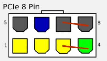
I have a feeling its the 6 to 8 pin adapter that I am using. I have attached the diagram below. The red lines represents where the cable gets the 2 extra sources from. IS this the correct way? if not could someone tell me what the correct way is so I could mod this cable to make it work?

Sorry for my english and hope I make since.
 

Attachments

  • pinout-pcie.png.324dcb7cd940ba4413b5350aec152d23.png
    pinout-pcie.png.324dcb7cd940ba4413b5350aec152d23.png
    19.7 KB · Views: 2,186
I'm seen over and over again that I need 1 6 - 6 pin and one 6 - 8 pin. Which I have, but I don't think my 6-8 pin is the right layout.
[doublepost=1537583478][/doublepost]I have this video card,
In this video the guy is using a 6-8 pin, just trying to find out where to remap the 2 extra pins too. Since my cable is a little different. Any ideas?
[doublepost=1537583527][/doublepost]Oh and around 4:38 in the video he shows the cable.
Thanks!
 
Hey Folks,
So I just bought a Gigabyte R9 280X Rev2 and a 6 mini pcie - 8 pin cable from Amazon.

When hooking everything up, the fans don't spend and the screen doesn't come on in Windows or Mac OS (Can remote in though).

I have a feeling its the 6 to 8 pin adapter that I am using. I have attached the diagram below. The red lines represents where the cable gets the 2 extra sources from. IS this the correct way? if not could someone tell me what the correct way is so I could mod this cable to make it work?

Sorry for my english and hope I make since.
[doublepost=1537587848][/doublepost]
You still need a Mac video card. The newer PC Cards do not have the rom cops for Mac. I run mine with two video cards. After loading the drivers the second video card works.
 
My problem McP2010

1st GPU Evga 680mac
2x6pin 190 watt max

2nd PNY Nv.Quadro k5000PC
1x6pin 122 watt max

How to drive this combo any suggestions please?

I would prefer not to disconnect my single DVD drive ...
 
So if I'm understanding this right, to even out the load across the two mini 6 pin video connector on our motherboards with any dual power connector card. We can get the dual mini 6 pin to single 8 pin male AND get the single 8 pin female to dual 6+2 for any card, or get whatever accommodates your card since it will spread the load evenly across the two mini 6 pin ports. This seems to be an especially good idea for the cards with 6 pin and 8 pin inputs on the same card, Brilliant! Hopefully no issue with bridging the two power channels from the supply if separate, but this has been used often with the RX 580's with success so it all seems very sound.
 
So if I'm understanding this right, to even out the load across the two mini 6 pin video connector on our motherboards with any dual power connector card. We can get the dual mini 6 pin to single 8 pin male AND get the single 8 pin female to dual 6+2 for any card, or get whatever accommodates your card since it will spread the load evenly across the two mini 6 pin ports. This seems to be an especially good idea for the cards with 6 pin and 8 pin inputs on the same card, Brilliant! Hopefully no issue with bridging the two power channels from the supply if separate, but this has been used often with the RX 580's with success so it all seems very sound.

Correct, this almost always work for 6+8 pin card.

Because 6pin rated 75W, 8pin rated 150W, and 6+8 total rated up to 225W.

And each mini 6pin can practically deliver up to ~120W. Therefore, total ~240W available for 225W demand.

However, this will be very very close to the shutdown limit (if the card really draw full 225W from 6+8pin). So, the cMP may still trigger the shutdown protection when GPU power spike happen. But this rarely happen in real world apps.
 
  • Like
Reactions: Reindeer_Games
Some observations I have found interesting:

I guess the over current protection must be on the motherboard not within the power supply since people have had improved conditions with the pixlas mod. The motherboard also must have individual over current shut off on each port since the info I've read the RX 580 had improved conditions due to the bridging cable.

Improved condition = no shutdown
 
In studying the adapters the dual mini 6 pin to 8 pin that plugs into a video card has two merged pins on the 8 pin side, the 8 pin female to dual 8 pin male adapters do not accommodate the merged pins as video cards do. Some of the ground wires would be rerouted but in testing the mac pro all grounds go to the same place so it should not matter. All the + power wires line up exactly. Any idea why they make two different styles of 8 pin plugs? Perhaps to prevent something but I can't figure out what? It seems like you could make this work like in your setup with an xacto, similar to the powerlink but without the capacitor. Does anyone see anything wrong with modifying the connector to make it fit for our purposes? I think it will work great.


Screen Shot 2018-12-03 at 9.14.06 AM.png Screen Shot 2018-12-03 at 9.42.07 AM.png
 
Last edited:
In studying the adapters the dual mini 6 pin to 8 pin that plugs into a video card has two merged pins on the 8 pin side, the 8 pin female to dual 8 pin male adapters do not accommodate the merged pins as video cards do. Some of the ground wires would be rerouted but in testing the mac pro all grounds go to the same place so it should not matter. All the + power wires line up exactly. Any idea why they make two different styles of 8 pin plugs? Perhaps to prevent something but I can't figure out what? It seems like you could make this work like in your setup with an xacto, similar to the powerlink but without the capacitor. Does anyone see anything wrong with modifying the connector to make it fit for our purposes? I think it will work great.


View attachment 808164 View attachment 808165

8pin CPU vs 8pin PCIe
 
  • Like
Reactions: Reindeer_Games
In my Case I do not care about 8 pin , I have two cards with kepler one 2x6pin other 1x6pin but on the motherboard from Mac Pro As far as I know they're only two 6 Pin power connectors for GFx
[doublepost=1544471472][/doublepost]___________________
I would like to split two connectors in 3x6 pin connectors

And I know from other conversation cables can transport up to 100 W

I'm looking into something like this as well.

Would anyone think linking two Powerlink's running directly both PCIe Boosters A and B to Jumper 2 (closest to 90 deg bend) of the Powerlink, and linking them on Jumper 1 (behind the current draw, allowing any remaining amperage to be available for conditioning)? From an alternating current perspective I believe this would work, but am unsure with direct current and being software controlled...? I'm pretty sure it wouldn't be much different since they are already being combined via power rail..?

I'm considering a short-term GPU fix of getting another 770 to go into SLI-but drop the TDP on the ROM of the second to ~110-120w to cap them.
 
Last edited:
@h9826790 I am about to order the powerlink adapter and wanted your advice on connecting it to the two PCIe 6-pin backplane plugs as EVGA states that both 8-pin PSU inputs on the powerlink should be connected. Would 2 x 16 AWG - 6 to 8-pin cables connected to the PCIe plugs do the job or do you advise against it?

I initially thought of using a short dual 6-pin to 8-pin cable to connect the PCIe plugs to a single 8-pin socket on the powerlink but then came across EVGA's statement in the manual.

I am connecting the powerlink to an EVGA GTX 780 6GB card for now but wanted to have the setup ready for when I upgrade the gpu in the future.

Thank you!

You only need 2x normal mini 6pin to 6pin. No need any 8pin cable. The PowerLink input can accept both 6pin and 8pin.
 
  • Like
Reactions: w1z
You only need 2x normal mini 6pin to 6pin. No need any 8pin cable. The PowerLink input can accept both 6pin and 8pin.
I see. So it's better to limit the power draw by using 2 x 6-pin cables plugged into the 2 x 8-pin sockets of the powerlink which then plugs into the 6 and 8 pin power inputs of the card.

Thank you!
 
I see. So it's better to limit the power draw by using 2 x 6-pin cables plugged into the 2 x 8-pin sockets of the powerlink which then plugs into the 6 and 8 pin power inputs of the card.

Thank you!

It won’t limit the power draw. It’s the card to decide to draw how much power, not the cable between cMP and PowerLink.
 
@h9826790 Thanks for your advice.

I installed the powerlink a couple of days back and all is in order. I did, however, notice my PSU stopped buzzing (from time to time) after installing the powerlink which is super great!! Can someone with the powerlink installed confirm this?

IMAG0364.jpg

Cheers
 
  • Like
Reactions: h9826790
Register on MacRumors! This sidebar will go away, and you'll see fewer ads.