Become a MacRumors Supporter for $50/year with no ads, ability to filter front page stories, and private forums.
i have same error. after disabled virus scanner and desolder L2406 (desolder only for flashing dmux) works fine.

after flashing solder L2406 back and macbook works.


+1 For the L2406. Been trying all day with 3 different boards, was starting to think my Lattice was dodgy. Saw your post, had nothing to lose so I removed L2406 and it flashed first go. This board's GPU was so dead the screen didn't light up and it had absolutely no video output. Now it is alive again.
 
+1 For the L2406. Been trying all day with 3 different boards, was starting to think my Lattice was dodgy. Saw your post, had nothing to lose so I removed L2406 and it flashed first go. This board's GPU was so dead the screen didn't light up and it had absolutely no video output. Now it is alive again.

Great good to hear. theses machines are so great for the age. I'm flashing every 2011 15 I get with this even if there not failing its worth it the cpus are very fast also iv had no problems with hd graphics 3000. you can just pop 16gb 1600mhz ram and a 1tb ssd and these machines will last another 10 years.. and now that the failed and gpu is disabled no worries about it failing ...
 
@dosdude1,
Saw this thread and subscribing to it. As my soldering skills are... questionable, waiting for the custom connector to be available so I can flash my MBP 2011.

A question if I may: If/when you get the brightness working in the flash, if we have already purchased/flashed our systems, would we need to pay for the updated rom or would we be able to re-flash it with the updated code?

Again, thanks for ALL the research and work you put into this. It is appreciated more then you will probably ever know (or maybe you have.. either way, you have my thanks).

Cheers.
Nope, if a firmware update is required, you will not need to pay for it a second time.
 
@dosdude1
Thanks for your prompt reply.
One last question (and maybe it's been answered here not sure, but I didn't' see it). After the reflash is there still considerable amount of power being applied to the AMD gpu, and if so, is it worthwhile to remove the AMD chip (or a resistor, etc...) or is the amount of heat/power consumption not worth it?

Thanks again!
PS - Didn't realize you were the one that created the Mojave patcher. <high five> Thanks to you, I now have Mojave installed on my old Macbook air! You sir are gentleman and a scholar!
My custom gMux IC firmware cuts all power to the dedicated GPU, so you don't need to worry about that at all.
 
Last edited:
  • Like
Reactions: LordHighBinary
So I flashed the gmux on this board, previously it had no video or backlight at all, so I have an improvement. Anybody know why it's green and fuzzy? Screen is known to be good (apart from the 2 vertical lines) connectors are clean and undamaged.
20190516_004831.jpg
 
So I flashed the gmux on this board, previously it had no video or backlight at all, so I have an improvement. Anybody know why it's green and fuzzy? Screen is known to be good (apart from the 2 vertical lines) connectors are clean and undamaged. View attachment 837131
That looks to me like a bad LVDS cable... Do you have a different screen you can test with? Chances are that's all it is.
 
That looks to me like a bad LVDS cable... Do you have a different screen you can test with? Chances are that's all it is.

OK so against my better judgement I tried it with a few different screens (that one is my "test screen" and has always worked fine) and it does work better with other screens. Never perfect though. Colours come right, but still a bit screen door like. I am putting it down to a dodgy lvds socket. I'll have to order some.

So you were correct ish Collin.
 
Hi
Trying to understand LVDS clock. All information on differentiated signals tell me that I should have a 100 Ohm resistor at the receiver termination? looking at the schematics and board view for a 820-2915b, the lvds_ig_a_clk_n line terminates before the gmux ic. Meter test shows this pad to be a common ground? is this correct or am I looking at another fault besides dedicated gpu?
Yeah, that's correct. Both the LVDS clocks for the integrated and dedicated graphics terminate at the gMux IC, which then takes the appropriate one based on the active GPU, splits it off into two (CLK_A and CLK_B), and sends it out to the screen. As for the measurement to ground, chances are your multimeter's tolerance for continuity is higher than the resistance of that rail to ground. It's probably such a low resistance that the multimeter reads it as being a connection.
 
  • Like
Reactions: 0134168
dosdude1, do you repair macbooks? have 2 macbooks 17 with fried GPU´s, and thought I bought 2 cmux, I don´t have the skills to proceed. Thank you.
 
Is there a way to get a copy of the original (flashed) efi rom with the lattice?

If something goes wrong...

Thx
 
Is there a way to get a copy of the original (flashed) efi rom with the lattice?

If something goes wrong...

Thx
To be honest there really isn't much point. If you have a dodgy gpu, as 80% of these 2011 15" macs do, then there is no advantage to going back. Its not like an eeprom that can cause bricking of your device. Through the jtag interface you always have access and could program a blank chip, a corrupted flash etc. I have a copy of the original, and I'm sure others do to. IF it is ever necessary we can supply it. This is a very safe procedure so just go for it.
 
Is there a way to get a copy of the original (flashed) efi rom with the lattice?

If something goes wrong...

Thx
Due to the nature of an FPGA, it can't be "dumped", as it isn't like an EEPROM, which stores data. So, flashing it is by all means a permanent operation.
 
And when there is something goes wrong?
Nothing can go wrong that cannot be fixed, if the flashing fails, just keep trying until it succeeds. It is impossible to permanently brick the chip.
 
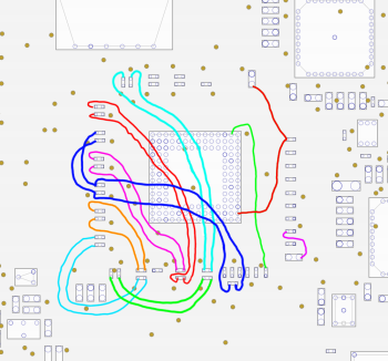
I've created diagram for 820-2914 MacBook Pro 17 A1297. Checked and it works fine.
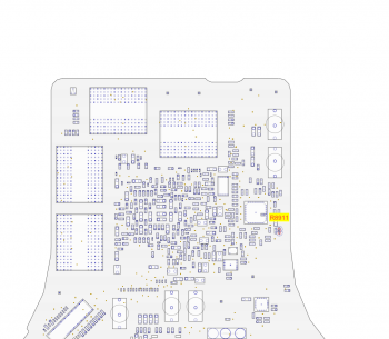
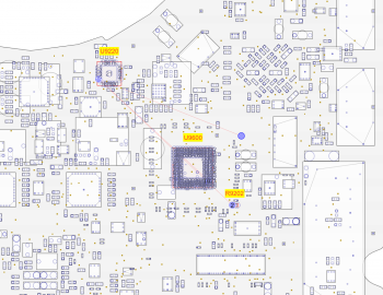
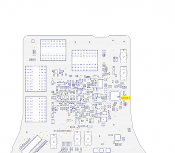
After all if MacBook runs fine, remove resistor R8911.
 

Attachments

  • 820-2914.png
    820-2914.png
    338 KB · Views: 1,559
  • Zrzut ekranu 2019-05-30 o 00.11.09.png
    Zrzut ekranu 2019-05-30 o 00.11.09.png
    272 KB · Views: 1,034
Last edited:
  • Like
Reactions: Matejh
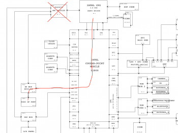
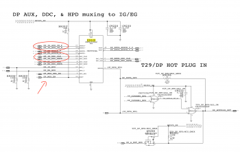
Have anybody idea if there is any method to make DP work again?
In schematics I found that there is DP MUX that has signals from Integrated Graphics and External but im not sure how to wire it correctly.
 

Attachments

  • Zrzut ekranu 2019-06-02 o 20.15.04.png
    Zrzut ekranu 2019-06-02 o 20.15.04.png
    472.5 KB · Views: 717
  • Zrzut ekranu 2019-06-02 o 20.16.36.png
    Zrzut ekranu 2019-06-02 o 20.16.36.png
    525.5 KB · Views: 771
  • Zrzut ekranu 2019-06-02 o 20.17.03.png
    Zrzut ekranu 2019-06-02 o 20.17.03.png
    745.4 KB · Views: 1,371
Have anybody idea if there is any method to make DP work again?
In schematics I found that there is DP MUX that has signals from Integrated Graphics and External but im not sure how to wire it correctly.
That's just for the control lines, unfortunately. The other DP lines from the PCH are no connect, making even soldering wires impossible.
 
  • Like
Reactions: godman
Those are all known issues with the software modification under macOS 10.13 and later. The only thing you can do is downgrade to an earlier version of macOS, or perform the hardware modification detailed in the OP of this thread.
Imagine my surprise when screen dimming returned today! Since our original exchange I've installed Mojave using your patcher and that went fine. Today I was alerted to Legacy Video support, and BAM!!

So I'm curious: Is this a known and expected result? Anything else I should look for, like sleep-on-close?

[update] And now it's gone again. Keys don't work and no slider in Display Settings. It was fun while it lasted.
 
Last edited:
First post, long time lurker and subscriber to your Youtube channel (@dosdude1). A hypothetical (not really) question, if say an idiot with a soldering iron damaged (read used too much heat and they came off) the pads on the logic board, are there other spots that one could connect to in order to flash the gmux using your firmware and the usb tool?
 
First post, long time lurker and subscriber to your Youtube channel (@dosdude1). A hypothetical (not really) question, if say an idiot with a soldering iron damaged (read used too much heat and they came off) the pads on the logic board, are there other spots that one could connect to in order to flash the gmux using your firmware and the usb tool?

Yes. You need schematics and openboardview program (both available if You search google). You will be able to see other connection points this way.
 
I've created diagram for 820-2914 MacBook Pro 17 A1297. Checked and it works fine.
After all if MacBook runs fine, remove resistor R8911.

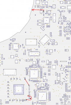
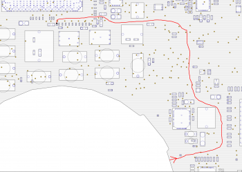
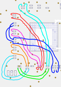
My 17" would not work with Your diagram. It would turn on to white screen with no image (maybe because of the 1920x1200 screen). So first I went with the diagram of Matejh for the 15" and made it work for my 17". Everything works, however backlight would turn off with a flash on sleep/shutdown and backlight turn on was not so smooth. After that I tried to follow the directions of Dosdude1 in one of the threads:

- Connect LVDS_IG_BKL_ON to LCD_BKLT_EN
- Connect LVDS_IG_PANEL_PWR to LCD_PWR_EN
- Connect PP3V3_S0 to LCD_BKLT_PWM

And this worked perfectly. Backlight turns on smoothly and turns off without any flashes. One wire has to go to the other side of the logicboard, but no need to remove GMUX. Diagrams attached. R8911 HAS to be removed!
 

Attachments

  • BackLight:LCD ON 17inch_a.png
    BackLight:LCD ON 17inch_a.png
    376.8 KB · Views: 851
  • BackLight:LCD ON 17inch_b.png
    BackLight:LCD ON 17inch_b.png
    509.4 KB · Views: 887
  • DATA Lines 17inch.png
    DATA Lines 17inch.png
    740.2 KB · Views: 796
  • R8911.png
    R8911.png
    272 KB · Views: 905
Last edited:
Register on MacRumors! This sidebar will go away, and you'll see fewer ads.