Yes. Search for the 820-2915 board view (.bdv) file on Google. You'll also need openboardview to read the file. Most of the alternative pads are much smaller though.Help! I accidentally pulled TCK pad while was switching it on, is there any other place I can solder it?
Got a tip for us?
Let us know
Become a MacRumors Supporter for $50/year with no ads, ability to filter front page stories, and private forums.
MBP 1,1-10,2 Permanently Disable 2011 15"/17" MacBook Pro Dedicated GPU - gMux IC Bypass
- Thread starter dosdude1
- Start date
- Sort by reaction score
You are using an out of date browser. It may not display this or other websites correctly.
You should upgrade or use an alternative browser.
You should upgrade or use an alternative browser.
Anyone else having issues with the programmer signals being pulled low by the board? My TCK is effectively getting clamped at 0.3-0.5V. TDI/TDO are also being held low and the programmer can barely make a ripple in the lines. Removing R9605 (to disconnect the Lattice JTAG I/F from the thunderbolt and PCH JTAG I/F) restores signal levels to TDI/TDO, but TCK is unchanged.
With R9605 installed, Device ID is 0x00000000. With it removed Device ID is 0xFFFFFFFF.
From what I can see, no one else has had to make any mods to boards aside from connecting the programmer (no the piddly 100p cap won't and doesn't help - the TCK high threshold is 3V shy of where it should be). I've tried this on three boards now and all of them behave exactly the same way; TDI/TDO held low unless R9605 is lifted and TCK never exceeding 0.5V (Checked with a scope).
Programmers tested:
- Clone HW-USBN-2A
- Digilent JTAG-HS1
- MachXO3 EVK on-board FTDI programmer.
Most of my attempts were with the HS1, as I tested whether it could program the MachXO3 with Diamond and it could. Therefore it should be able to program the XP2 as well. FWIW the clock and data waveforms actually look good. Edges are sharp, no ringing. No, it's not the DC-DC inductor - my wiring leaves port side of the board.
I just don't understand why something which should be so simple is being such a pain in the a$$.
With R9605 installed, Device ID is 0x00000000. With it removed Device ID is 0xFFFFFFFF.
Code:
INFO - Check configuration setup: Start.

Device#1 LFXP2-5E: Failed to verify the ID
(Expected: 0x01299043 Read: 0xFFFFFFFF).

ERROR - Check configuration setup: Unsuccessful.

ERROR - Programming failed.
From what I can see, no one else has had to make any mods to boards aside from connecting the programmer (no the piddly 100p cap won't and doesn't help - the TCK high threshold is 3V shy of where it should be). I've tried this on three boards now and all of them behave exactly the same way; TDI/TDO held low unless R9605 is lifted and TCK never exceeding 0.5V (Checked with a scope).
Programmers tested:
- Clone HW-USBN-2A
- Digilent JTAG-HS1
- MachXO3 EVK on-board FTDI programmer.
Most of my attempts were with the HS1, as I tested whether it could program the MachXO3 with Diamond and it could. Therefore it should be able to program the XP2 as well. FWIW the clock and data waveforms actually look good. Edges are sharp, no ringing. No, it's not the DC-DC inductor - my wiring leaves port side of the board.
I just don't understand why something which should be so simple is being such a pain in the a$$.
Yes, it will indeed. I've had a few people use DeMux on a board with the GPU and VRAM chips removed, and it worked just fine.
I really interested myself in that. is there any wiring diagram to disable the GPU in that 17" MacBook pro?Yes, it will indeed. I've had a few people use DeMux on a board with the GPU and VRAM chips removed, and it worked just fine.
[automerge]1589586284[/automerge]
Have you already done this before?Can confirm it works. As long as the 1v8_s0 rail is still intact through to all_sys_pwrgd.
Yes, I received a board where the gpu had been totally removed, after gmux flash it worked fine. My comment was more in relation to messing with the circuit that feeds the gpu with 1.8v. That circuit needs to remain intact (and not shorted) up to the point where it's pgood signal meets all_sys_pwrgd, otherwise the board will obviously not turn on fully. 1v8 is also required by the PCH (u1800). If you look for all_sys_pwrgd on the board view, you can trace it back to where 1v8s0_pgood meets it. If 1v8 is missing or shorted it will pull all_sys_pwrgd low through r7966. In saying that it is also unnecessary to remove any of these components as dosdude1's gmux takes care of that. If you REALLY want to make sure the gpu gets no power you can safely remove U7880 or the gpu_en resistor R9932.
OH, thanks, your answer was very clearifing to me.Yes, I received a board where the gpu had been totally removed, after gmux flash it worked fine. My comment was more in relation to messing with the circuit that feeds the gpu with 1.8v. That circuit needs to remain intact (and not shorted) up to the point where it's pgood signal meets all_sys_pwrgd, otherwise the board will obviously not turn on fully. 1v8 is also required by the PCH (u1800). If you look for all_sys_pwrgd on the board view, you can trace it back to where 1v8s0_pgood meets it. If 1v8 is missing or shorted it will pull all_sys_pwrgd low through r7966. In saying that it is also unnecessary to remove any of these components as dosdude1's gmux takes care of that. If you REALLY want to make sure the gpu gets no power you can safely remove U7880 or the gpu_en resistor R9932.
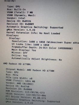
Hi, I got an A1286-2011 in today and when i turned on to use the intel graphics chip, it showed only of 7mb today. I was wondering any of you have ever run into this problem before and what could possibly cause this?
I attached its picture fyi.
Thanks for any comment.
Updated: My bad. I realized I used the wrong the wrong hdd that was installed on another macbook, and thus it did not recognize the video card. All good now.
I attached its picture fyi.
Thanks for any comment.
Updated: My bad. I realized I used the wrong the wrong hdd that was installed on another macbook, and thus it did not recognize the video card. All good now.
Attachments
Last edited:
What OS is it running? If Mojave or later, the Legacy Video Card Patch needs to be installed with the respective patcher's Post-install tool.Hi, I got an A1286-2011 in today and when i turned on to use the intel graphics chip, it showed only of 7mb today. I was wondering any of you have ever run into this problem before and what could possibly cause this?
I attached its picture fyi.
Thanks for any comment.
Also, does the GPU problem makes the machine not to boot up even with the NVRAM command? It does freeze around half way on the apple logo.
I’ve been trying to do dosdude gmux flash for almost 8 months now with constant failure...first I thought was the soldering, then I thought it was the wire I gave up for quite a while and I decided to try again today..first update myself with this forum then I started to work on it trying the 100pf capacitor and immediately it fail...I continue trying with more failures...then I decided to open the Lattice programmer and my problem was right in front of me...most of the pin out for the programmer had horrible solder joints...so I re-soldered all the pins....and I tried the demux again and immediately it worked with the first try...so if anyone is still getting failure with good solder joint and good wire...ITS THE LATTICE PROGRAMMER ****** pinout needs re-soldering
I tried today with a Lattice programmer that I purchased on Ebay. Here is the linkI’ve been trying to do dosdude gmux flash for almost 8 months now with constant failure...ITS THE LATTICE PROGRAMMER ****** pinout needs re-soldering
but the item has been removed citing "this listing was ended by the seller because there was a error with the listing" Maybe they mean the error was that the programmer was faulty and that I was wasting my time trying to use it. I spent all afternoon trying to flash DosDude1's Demux firmware onto a 2011 A1286 with no luck. I just pulled mine apart and the soldering appears surprisingly good with no obvious defects. The funny coloured LED does change colour when the Macbook auto starts upon the magsafe being plugged in but none-the-less the flash still fails every time. I am not sure if I should try the removal of L2406 or adding a 100pF capacitor between TCK and ground but I suppose that I have nothing to lose. Initially with the unit in the housing I could not see a change in the colour of the LED as the Macbook started. However now with the board out of the housing there is a definite change in the LED but certainly not amber to green like the Lattice programmer that Collin was using.
Last edited:
My Lattice box finally came. However, I followed all the steps but it still got an error.
Wire code as instructed.
I checked the programmer.log and here it is, but i could not locate the XPLD.jed file.
Connected to Lattice Cable Server.
USB V2.0 detected.
Check configuration setup: Start.
File C:\Users\Lenovo\AppData\Local\Temp\15992\program\data\vmdata\database\xpga\xpld\XPLD.jed
has been modified since last check.Default using the modified file.
Device#1 LFXP2-5E: Failed to verify the ID
(Expected: 0x01299043 Read: 0xFFFFFFFF).
Check configuration setup: Unsuccessful.
Please help.
Attached are the diagrams for soldering the jumper wire to enable backlight brightness control using the battery status indicator button on both a 15" and 17" board. Also, here's a video showing exactly how backlight control using that button works.
Using the keyboard keys will require some changes to the DeMux firmware, so I'll let you know when that's available. Soldering jumper wires to different locations will be necessary, as I mentioned before.
View attachment 900845View attachment 900846
I just flashed a 17" 2011 macbook pro and the screen is working fine but after adding the line from SMC_BIL_BUTTON_L to GMUX_VSYNC the display brightness is going up and down.....the battery is almost 0% so I'm charging it now....but do I need to do an SMC reset to get the brightness control to work? I've double checked the boardview diagram and the it seems that I have the right pins as indicated.
Appreciate some help on resolving this.
Thx
The button itself could be bad, causing the line to go low. Make sure you soldered the wire to the correct side of that resistor right next to the SMC... The other side is connected to GND, which will keep the line low all the time if connected there.I just flashed a 17" 2011 macbook pro and the screen is working fine but after adding the line from SMC_BIL_BUTTON_L to GMUX_VSYNC the display brightness is going up and down.....the battery is almost 0% so I'm charging it now....but do I need to do an SMC reset to get the brightness control to work? I've double checked the boardview diagram and the it seems that I have the right pins as indicated.
Appreciate some help on resolving this.
Thx
The button itself could be bad, causing the line to go low. Make sure you soldered the wire to the correct side of that resistor right next to the SMC... The other side is connected to GND, which will keep the line low all the time if connected there.
Actually I charged the battery last night from near 1% charge and noticed that ability to dim is working now. I guess the low battery voltage caused this random behaviour of it cycling up and down. I checked the button connector previously and it seemed fine. Now that the battery has a proper charge it's working.
I finally got the programmer to see the FPGA! I found a thread here that solved my TCK problem. @fastlogon , it looks like you were having a similar issue to me. Give the instructions in that thread a go. Perhaps it will help you.
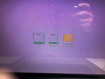
Hi guys and thanks @dosdude1 for all this effort, my question is, i've done the bypass by wires as on page 1, both macs work perfect for like a month or two, but now one mac is showing blue or purple screen with chime but no apple logo, the other one is doing some artifacts al over the screen and going like pinkish. Any ideas? both have MUX removed, and one has a missing AMD GPU
Attachments
The pitch is 1.2MM.Hi all, Is anyone able to tell me what the pitch of the 6 pins on system board is?
e.g. is it 1.27mm (distance between the pads). Many thanks!
Register on MacRumors! This sidebar will go away, and you'll see fewer ads.


