Become a MacRumors Supporter for $50/year with no ads, ability to filter front page stories, and private forums.
Hello everybody, and thanks for sharing your knowledge. I have a mbp motherboard 820-2330a and its giving me a dim green light at the adapter, after reading the schematics and comparing it , i found out that it may be the d7005 zener 1ss418 the part that went bad and is not giving me the chargerdcin on u7000.

I've been searching the web for this part and its a "TOSHIBA Diode Silicon Epitaxial Schottky Barrier Type 1SS418 High Speed Switching Application Low forward voltage : VF (3) = "

Do you guys know if this part is known by or with a different notation??? I cant seem to find it under the 1ss418 on digi key or mouser.com. Could you please guys help me find this component to buy it? Thanks in advance

Hi,

Looking at the data sheet for the device, it is 7 years old - positively antique for electronic components. Just replace it with a modern diode with the same or better specifications and you should be fine.

Regards,

Chigwelldave.
 
Hi,

Looking at the data sheet for the device, it is 7 years old - positively antique for electronic components. Just replace it with a modern diode with the same or better specifications and you should be fine.

Regards,

Chigwelldave.

hi chigwelldave, and thanks for the quick response. I.m looking at the data sheet but having trouble finding a good replacement, could you please guide me a bit,thanks again!!!

update: I think i found it!!!
http://www.digikey.com/product-sear...=1&stock=1&quantity=0&ptm=0&fid=0&pageSize=25

http://pdf1.alldatasheet.com/datasheet-pdf/view/212880/TOSHIBA/1SS418.html
 
Last edited:
schem and board file

Thanks for reply my post.
my board is MBP 2009 EMC No: 2326
i try to recharge with/without battery its really hot and i try put the battery reallly hot also.

and i have broken logicboard from MBP 2010 and 2011...u think they have same part that i can take from that?

cheers!
ajie

ajiebali:
if this is not the right schem and board view there should be a board id like the one in the attached image. it takes a magnifying glass or REALLY good eyes to see it...

chigwelldave probably already told you all you need to know though, and provided part numbers as well.....
 

Attachments

  • A1278 820-2530 K24 +BRD.zip
    1.4 MB · Views: 385
  • macbookSerialforBoard.jpeg
    macbookSerialforBoard.jpeg
    29.3 KB · Views: 1,636
Hi,

Assuming your board is an 820-2530, that's the dual diode for supplying G3Hot from either the battery or Magsafe. It is a SOT665 diode type HN2D01JEAPE, circuit reference D6905.

Regards,

Chigwelldave.

Many thanks Brother, i will check my board and let u know.


ajiebali:
if this is not the right schem and board view there should be a board id like the one in the attached image. it takes a magnifying glass or REALLY good eyes to see it...

chigwelldave probably already told you all you need to know though, and provided part numbers as well.....

okay i really appreciate with this, i will check my board and posting again here.
Thanks mate

Cheers!
ajie
 
Great Job on all those who answer the questions here.

My electronics experience is pretty much the radioshack kit that had springs to make circuits, but it was fun.

I have a late 2009 macbook pro that suffered a coffee spill. i got a 2010 to practice on for $50 dollars before i destroyed the pretty one.

Apple Macbook Pro A1286 (2010,K18,820-2850,i5)

I have no G3HOT, and traced back as best as i could to find no 18.5v output of the U5805 chip.

My question is "before i rip the chip off of the board, is there some component down the line that would cause 0v output? pin 8 does not short to ground and has 0v is the chip in need of replacement?" 4.99v is at pin 2.


---------

also:
MIN_LINE_WIDTH=0.50MM
MIN_NECK_WIDTH=0.20MM
VOLTAGE=5V

is that info for wave analysis if using a scope or???

thanks
fdk:confused:

Hi,

The 18.5V supply is for sensors as far as I know - nothing to do with G3HOT. G3HOT is generated by a 3.3v buck switching regulator fed via a double diode from either the battery or Magsafe.

The size data is for the people designing the PCB layout, I believe.

Regards,

Chigwelldave.
 
MacBook air A1369 mid 2011

I have a problem with a Mac. The Keyboard was full of dog hair and de PowerButton among others was not working. I changed de keyboard, all the keys work now except for the powerbutton. i can turn him on. if i remove the battery, when i plug the magsafe it starts. even when it is turned on, the power button is not responsive.

i can't do the standard SMC reset.

I got schematics and tried to get some data in voltages from the SMC.

G3Hot is at 3.4V but the SMC_ONOFF_L is at 0.32V. It should be on 3.4 since is pulled-up from G3Hot from a 10K res. I see that SMC_ONOFF_L is input for U5010(in my case) SMC POWER (SN0903048) so that is the chip that is doing the startup and reset of the SMC. Could it be broken? It has a SMC_MANUAL_RST_L that is at 2.7V and when put to low it shuts down all (The SMC_RESET_L get low).

In the schematics is a info that if a put SMC_ONOFF_L and SMC_TPAD_RST_L in low it should reset SMC. But it doesn't work.

Some suggestion on what to do next?
 
A1278 2010 no power, still finding issue

:mad::mad:
@CMDRDATA

Hi Boss,

I keep working on this a1278 2010 board that no power on.
3,42v present
charge battery
51125 ok

Some post before you mentioned find ALL_SYS_PWRGD.
i take some measurements.
Anyway i replace this component and no change in the board.
Do you know how to follow this line ALL_SYS ?

Need i measure from PGOOD out each Vcore component ( 51125,MCP,CPU,RAM) .

Thanks!


Now arrive another A1278 2010 board
Same problem, all volt are correct but does not power on, no overheat.

I check all ALL_SYS circuit with another full working board and all values are correct. I dont know where i need to follow with this board.
 
  • Like
Reactions: deserthermit
:mad::mad:


Now arrive another A1278 2010 board
Same problem, all volt are correct but does not power on, no overheat.

I check all ALL_SYS circuit with another full working board and all values are correct. I dont know where i need to follow with this board.

Hi,

The next rail to come up is your CPU VCore - controlled by U7400.

Regards,

Chigwelldave.
 
ajiebali:
if this is not the right schem and board view there should be a board id like the one in the attached image. it takes a magnifying glass or REALLY good eyes to see it...

chigwelldave probably already told you all you need to know though, and provided part numbers as well.....

Hi man, Yes my Board number is: 820-2530
U give correct schematic, But i have little bit problem, i cannot open BRD file with eagle or kicad on my mac, they say BRD file is error bla bla

Did any way to convert BRD file into PDF file?

Cheers!
ajie
 
Hi man, Yes my Board number is: 820-2530
U give correct schematic, But i have little bit problem, i cannot open BRD file with eagle or kicad on my mac, they say BRD file is error bla bla

Did any way to convert BRD file into PDF file?

Cheers!
ajie

Hi,

No, you need the "board view (viewer)" application which runs under Wine.

Regards,

Chigwelldave.
 
POWER ON BOARD, Won't Power Up

Hi,

The 18.5V supply is for sensors as f...

Chigwelldave:

thanks! .... i am going to work on my 2009 8202523-B. I have g3HOT, but it is 3.99-3.4 ... is that "close enough" to 3.425? or ???

this is the board without startup pads, but when i try and force startup without the keyboard (pin5 to ground) i get nothing. 3.4 volts is present, but grounding it does nothing....


If i understand so far:


1. Battery or Magsafe provides 18.5v or +-12v to the board.

2. Rails are powered at 3.4, 1.5, and 12v and also 18.5

3 Attempted POWER_ON with power button creates a ground that causes the SMC to check its STATUS via sensors and if it likes what it sees it powers everything up.

4. Since I have Power To my SMC chip and can manually create the Power_On Ground Signal -- But without any actual Power_On occuring, then i must have a fault in on of the LOGIC GATES / Sensors that is keeping me from powering up.

5. Under these conditions U5001, and similar Gate Chips until I can find the one that is STOPPING me before i can power up.


( Am i getting close to the proper steps?)
thanks
fdk

Hi fdk,

Pretty close to the proper steps. There are 30+ stages from pressing the power button to booting. Most steps involve bringing up new power rails sequentially so that there is no sudden surge on the adaptor or battery. Have a look at the power system architecture diagram and the power sequencing page. An interesting signal to the SMC is the "ALL_SYS_PGOOD", without which the SMC will abort power up. Test that line to determine where to look (forwards or back) in the sequence. You will need the schematic and board view file to see where to take measurements.

Your G3Hot should be close enough, battery provides 10-12v (magsafe around 18v but is converted to 12v by the main PSU/charging circuit).

Regards,

Chigwelldave.
 
Last edited:
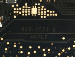
820-2523b

Chigwelldave:

thanks! .... i am going to work on my 2009 8202523-B. I have g3HOT, but it is 3.99-3.4 ... is that "close enough" to 3.425? or ???

this is the board without startup pads, but when i try and force startup without the keyboard (pin5 to ground) i get nothing. 3.4 volts is present, but grounding it does nothing....


If i understand so far:


1. Battery or Magsafe provides 18.5v or +-12v to the board.

2. Rails are powered at 3.4, 1.5, and 12v and also 18.5

3 Attempted POWER_ON with power button creates a ground that causes the SMC to check its STATUS via sensors and if it likes what it sees it powers everything up.

4. Since I have Power To my SMC chip and can manually create the Power_On Ground Signal -- But without any actual Power_On occuring, then i must have a fault in on of the LOGIC GATES / Sensors that is keeping me from powering up.

5. Under these conditions U5001, and similar Gate Chips until I can find the one that is STOPPING me before i can power up.


( Am i getting close to the proper steps?)
thanks
fdk


Hi Felix, did you check TPS51225 ? Is 3v 5v power supply.
 
a1286 won't power up 820-2535-B

820-2523-B
Hi fdk,

Pretty close to the proper steps. There are 30+ stages ...

Chigwelldave.

Ouch.... me head hurts...

Thanks Chigwelldave

I have the board view and schem ... It is an oddball and only took two weeks to find it. But I refused to pay some Russian Guy $80 for a complete set when this is probably one of the only times I will try fixing one of these...

(fingers crossed hoping it's the only time)

I found the Sequence Document and am trying to make sense of it.

also the video - if only i spoke Chinese.


nicoar10: yep, thanks.. working i think.


QUESTION: How do you know if a board is working? will it start up and spin the fan (one fan attached) if the logic board is outside the case? or does the hinge cover, video, drives, etc have to be attached to tell that you have a working board? i have just been attempting to "jump start" it with the battery, battery and magsafe, or magsafe only and the fan does not spin. should i plug at least the hinge cover in to test? or is the fan enough?


thanks again to all who take the time to respond... i appreciate the assistance!
 
Last edited:
820-2523-B


Ouch.... me head hurts...

Thanks Chigwelldave

I have the board view and schem ... It is an oddball and only took two weeks to find it. But I refused to pay some Russian Guy $80 for a complete set when this is probably one of the only times I will try fixing one of these...

(fingers crossed hoping it's the only time)

I found the Sequence Document and am trying to make sense of it.

also the video - if only i spoke Chinese.


nicoar10: yep, thanks.. working i think.


QUESTION: How do you know if a board is working? will it start up and spin the fan (one fan attached) if the logic board is outside the case? or does the hinge cover, video, drives, etc have to be attached to tell that you have a working board? i have just been attempting to "jump start" it with the battery, battery and magsafe, or magsafe only and the fan does not spin. should i plug at least the hinge cover in to test? or is the fan enough?


thanks again to all who take the time to respond... i appreciate the assistance!

A logic board will start up outside the case. I have a loose subwoofer/right speaker (4 wires) that I plug in so I can hear chime or error beeps. I have a DC-in board wrapped in kapton tape (to avoid accidentally shorting to loose board). Then I just touch the startup pads with tweezers to start (or you can use pin 5 keyboard to ground... same thing). Nothing else is required to at least see if board starts with a chime.

Order of initial go/no go testing I use is:


1) Green light on magsafe? If yes the G3Hot working.
1a) If no green light check for G3Hot = 3.4V.
1b) If G3Hot OK check ISL6259 charger pin 14 for 3V. This is signal from charger to SMC that it is happy.
1c) If pin 14 ok check output of ISL6259 for 12.6V. If not then ISL6259 circuit not working
2) Try starting with no memory. If MCP is good then it will give memory beeps. If no beeps then MCP is not reading memory. Probably bad.
3) If ISL6259 putting out 12.6V then check other voltage rails. Easiest to check all_sys_pwrgd point but you can also go rail by rail. Common failure point is the 3.3V/5V controller.

That at least gets you started in the right direction for further diagnosis. There is no magic answer to fix all of these. It takes some sleuth work and the ability to read schematics and board views.
 
820-2523-B


Ouch.... me head hurts...

Thanks Chigwelldave

I have the board view and schem ... It is an oddball and only took two weeks to find it. But I refused to pay some Russian Guy $80 for a complete set when this is probably one of the only times I will try fixing one of these...

(fingers crossed hoping it's the only time)

I found the Sequence Document and am trying to make sense of it.

also the video - if only i spoke Chinese.


nicoar10: yep, thanks.. working i think.


QUESTION: How do you know if a board is working? will it start up and spin the fan (one fan attached) if the logic board is outside the case? or does the hinge cover, video, drives, etc have to be attached to tell that you have a working board? i have just been attempting to "jump start" it with the battery, battery and magsafe, or magsafe only and the fan does not spin. should i plug at least the hinge cover in to test? or is the fan enough?


thanks again to all who take the time to respond... i appreciate the assistance!

Im working in the same board now but other issue.
With fan connected you can test the board out bottom case.
I attach picture power button.

Follow Dadioh steps:

1- 3,42 g3hot
2- 12v out from battery charger IC
3- 5v and 3v TPS51225
 

Attachments

  • la foto.JPG
    la foto.JPG
    257.1 KB · Views: 1,137
still cannot find solutions by self :(
Anyone got same problem like me before?
D6905 and R6905 burnt

My Board Number: 820-2530


cheers!

Ajie
 
still cannot find solutions by self :(
Anyone got same problem like me before?
D6905 and R6905 burnt

My Board Number: 820-2530


cheers!

Ajie

Hi,

With all power removed, check the resistance across the G3Hot input capacitor C6990 (should be high) then across the output capacitor C6999 (should also be high). If C6990 is low then either it or U6990 could be bad, if C6999 is low it, U6990 or anywhere on the G3Hot line could be bad. You can remove L6995 to isolate the line.

Regards,

Chigwelldave.
 
MackBook Pro Late 2011 K90i board not booting

Hi Team,
Nice thread and plethora of information here. Hope somebody can guide me too. I have a Late 2011 K90i 13" water damaged board. It was booting to a blank screen earlier (completely black screen, not just back-light issue). After properly cleaning and examining under the stereo microscope, I could see few solder joints eaten out by the rust. To name, T4001 and Q4262. Damage is limited to very few components only on the upper part of the board, rest of the board is very clean. I managed to solder visibly broken points under the stereo microscope and Resistance and Voltage reading for both T4001 and Q4262 is now matches with a working board.

However, now, the board doesn't even boot, fan spins and heat sink becomes extremely hot after supplying the power. Probably, some connection broke or became loose during cleaning, but no missing part.

I have done basic measurement and compared with a working board. The difference I am finding is between Q3880 and U3890.
My non-working board measuring a voltage of around 11.8V on few points with just battery connected whereas a working board measures 0V.

Seems to be a damaged Q3880 to me, but not 100% sure. Checking for advice before taking it out. Attached is the pic with details of points where I am getting around 11.8V instead of 0V.
K90i_1.PNG

Funny thing is that board went out during cleaning process even before my eBay ordered external display connector reached home and I couldn't test it with external display.

Pls advice if it's Q3880 damaged or U3890 or something else. I am new to reading schematics and still trying to make a sense out of it.

Edit: Forgot to mention that board responds to Megsafe and battery charging perfectly fine. Battery indicator lights showing correct charge status too.
 
Last edited:
Sorry if I'm asking something that's been asked before, but there's so many threads within threads.

Basically, I can turn a MacBook on with SMC bypass, but the magsafe LED is always off, tried it another MacBook and it does light up, battery does not charge.

I don't have any readings in SYS_ONEWIRE and SMC_BC_ACOK_VCC, I have 3.42V in PP3V42_G3H_ONEWIRE.

I've tried replacing MAX9940, TC7SZ08AFEAPE and ISL6259 with no results. The only thing I suspect is the magsafe dc/in board, however macbook can turn on with it.

Do we have a proven sequence test to follow?
 
Hi Team,
Nice thread and plethora of information here. Hope somebody can guide me too. I have a Late 2011 K90i 13" water damaged board. It was booting to a blank screen earlier (completely black screen, not just back-light issue). After properly cleaning and examining under the stereo microscope, I could see few solder joints eaten out by the rust. To name, T4001 and Q4262. Damage is limited to very few components only on the upper part of the board, rest of the board is very clean. I managed to solder visibly broken points under the stereo microscope and Resistance and Voltage reading for both T4001 and Q4262 is now matches with a working board.

However, now, the board doesn't even boot, fan spins and heat sink becomes extremely hot after supplying the power. Probably, some connection broke or became loose during cleaning, but no missing part.

I have done basic measurement and compared with a working board. The difference I am finding is between Q3880 and U3890.
My non-working board measuring a voltage of around 11.8V on few points with just battery connected whereas a working board measures 0V.

Seems to be a damaged Q3880 to me, but not 100% sure. Checking for advice before taking it out. Attached is the pic with details of points where I am getting around 11.8V instead of 0V.
View attachment 475440

Funny thing is that board went out during cleaning process even before my eBay ordered external display connector reached home and I couldn't test it with external display.

Pls advice if it's Q3880 damaged or U3890 or something else. I am new to reading schematics and still trying to make a sense out of it.

Edit: Forgot to mention that board responds to Megsafe and battery charging perfectly fine. Battery indicator lights showing correct charge status too.

It seems to getting worse. Now I am missing PP3V3_S0 on the board. It reads 0.10V with just Magesafe. Actually, when I supply power, fan spins for 2 seconds, during this brief period Q7820 outputs 3.36V of PP3V3_S0. However, fan stops after that and PP3V3_S0 becomes 0.10V.

Apparently, SMC not happy about something and dropping the power. No heating components now, even if power left connected. Still battery charges fine. Magesafe glows green with just power cord and becomes orange when connected with battery on board.

G3Hot reads 3.50V. SMC bypass method mentioned in the first post also not working.

Any idea what to test now? With earlier problem atleast I was trying to follow the power path from schematics, but now lost completely. Any hint will be greatly appreciated.
 
Last edited:
It seems to getting worse. Now I am missing PP3V3_S0 on the board. It reads 0.10V with just Magesafe. Actually, when I supply power, fan spins for 2 seconds, during this brief period Q7820 outputs 3.36V of PP3V3_S0. However, fan stops after that and PP3V3_S0 becomes 0.10V.

Apparently, SMC not happy about something and dropping the power. No heating components now, even if power left connected. Still battery charges fine. Magesafe glows green with just power cord and becomes orange when connected with battery on board.

G3Hot reads 3.50V. SMC bypass method mentioned in the first post also not working.

Any idea what to test now? With earlier problem atleast I was trying to follow the power path from schematics, but now lost completely. Any hint will be greatly appreciated.

Hi,

Check your All_sys_pgood or similar signal, perhaps the smc is shutting down due to a missing power rail. If this is ok, the next to power up are the CPU and ram supplies. Only once all the power is good and the ram is tested does the system chime and boot.

Regards,

Chigwelldave.
 
Hi,

Check your All_sys_pgood or similar signal, perhaps the smc is shutting down due to a missing power rail. If this is ok, the next to power up are the CPU and ram supplies. Only once all the power is good and the ram is tested does the system chime and boot.

Regards,

Chigwelldave.

Thanks Chigwelldave for the hint. Did you mean ALL_SYS_PWRGD signal? That will be difficult to catch, because looking from schematics it seems Q7950 produces ALL_SYS_PWRGD which in turn is dependent on PP3V3_S0. In my case, PP3V3_S0 drops to 0.10V within 1 second.

I tried to measure ALL_SYS_PWRGD within that brief duration and it was around 3.36V at pin 4 of Q7950. However, dropped to 0V the next second.

Not sure how to trace it. Has anybody faced this problem here earlier?

Q7950.PNG
 
Register on MacRumors! This sidebar will go away, and you'll see fewer ads.