Become a MacRumors Supporter for $50/year with no ads, ability to filter front page stories, and private forums.
Status
The first post of this thread is a WikiPost and can be edited by anyone with the appropiate permissions. Your edits will be public.
I guess it has nothing to do with the temperature and temperature sensor. The temperature is low.
View attachment 1962365View attachment 1962366
And every crash must be at Gaussian blue 34 seconds.Six crashes all occurred in this 34.
You need HW Monitor to run and observe to see if there are SMBUS conflicts, MFC will not show those.

I have the same type of card not running in a stable way with the WX4170 vBIOS versions. Even when not running a benchmark it will simply crash once in a while. Not worth the trouble.
 
I guess it has nothing to do with the temperature and temperature sensor. The temperature is low.
And every crash must be at Gaussian blue 34 seconds.Six crashes all occurred in this 34.
As I said - these crashes are probably related to your WX4170 GPU grade. You can try running the MetalBench benchmark, if the result is the same as with Geekbench, stick with WX4150 VBIOS.
 
I bought the WX4170 without the BIOS chip. Could you please suggest me how to process the flashing? I can't do the solder myself, therefore I will have to bring my stuff to the local phone repair shop for the soldering job. The shop can do the soldering job for me, but they don't do the flashing.

Which option should I choose? I do have the CH341a programer but haven't tried using it yet. And the shops I know won't do it all for me.

1. Solder the EEPROM chip on the temporary base, take it back home and flash it with CH341a Programer. Then bring it back to the shop to transfer the chip to the WX4170 card. This ensure the contact to the chip with CH341a programer.

2. Solder directly the EEPROM chip on the card, then install it to the iMac and flash with GRML USB method. Less soldering job, but with a blank EEPROM chip, can the card be recognized and flashed in Linux?

3. Solder directly the EEPROM chip on the card, the use the CH341a Programer with its clips. This requires less soldering job, but is it difficult to attach the clips of CH341a programer to the chip soldered on the card?
You can flash the single chip using the clip or you can wait after it has been soldered and use the Linux flash utility.

Most likely you can place the single chip directly on the CH341A device exactly there where currently the cable connection to the clip starts. Just check some youtube videos on this. Use in any case the WX4150 version!
 
I bought the WX4170 without the BIOS chip. Could you please suggest me how to process the flashing? I can't do the solder myself, therefore I will have to bring my stuff to the local phone repair shop for the soldering job. The shop can do the soldering job for me, but they don't do the flashing.

Which option should I choose? I do have the CH341a programer but haven't tried using it yet. And the shops I know won't do it all for me.

1. Solder the EEPROM chip on the temporary base, take it back home and flash it with CH341a Programer. Then bring it back to the shop to transfer the chip to the WX4170 card. This ensure the contact to the chip with CH341a programer.

2. Solder directly the EEPROM chip on the card, then install it to the iMac and flash with GRML USB method. Less soldering job, but with a blank EEPROM chip, can the card be recognized and flashed in Linux?

3. Solder directly the EEPROM chip on the card, the use the CH341a Programer with its clips. This requires less soldering job, but is it difficult to attach the clips of CH341a programer to the chip soldered on the card?
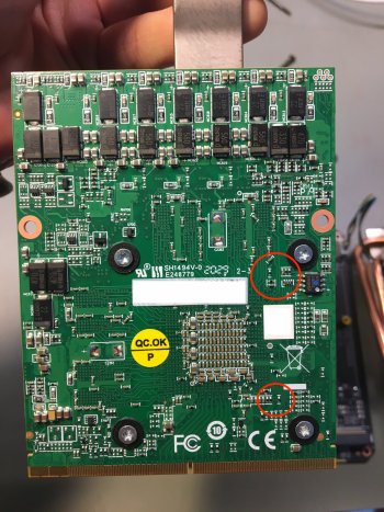
To add to @Ausdauersportler 's answer: If you have a clip and CH341a programmer, just program the bare (unsoldered) BIOS chip before bringing it to the 'soldering shop'. Also, while they are at it, do ask them to remove those two 0402-sized jumpers connecting the temp. sensor IC to the SMBus - thus you'll avoid address collisions in iMac11,x (and this has no side effect if the card will be used in an iMac12,2).
 
  • Like
Reactions: Nguyen Duc Hieu
I bought the WX4170 without the BIOS chip. Could you please suggest me how to process the flashing? I can't do the solder myself, therefore I will have to bring my stuff to the local phone repair shop for the soldering job. The shop can do the soldering job for me, but they don't do the flashing.

Which option should I choose? I do have the CH341a programer but haven't tried using it yet. And the shops I know won't do it all for me.

1. Solder the EEPROM chip on the temporary base, take it back home and flash it with CH341a Programer. Then bring it back to the shop to transfer the chip to the WX4170 card. This ensure the contact to the chip with CH341a programer.

2. Solder directly the EEPROM chip on the card, then install it to the iMac and flash with GRML USB method. Less soldering job, but with a blank EEPROM chip, can the card be recognized and flashed in Linux?

3. Solder directly the EEPROM chip on the card, the use the CH341a Programer with its clips. This requires less soldering job, but is it difficult to attach the clips of CH341a programer to the chip soldered on the card?
Also, take a look at back of the card and make sure RP1 resistor array is present:
1645437705187.png

If it's empty you'll have to have it soldered too.
 
21.5' 2009/2010/2011 iMac display cleanup ('ghosting' removal)

Below is a description on how to get rid of 'ghosting' (fine dust buildup within the display - between the actual LCD panel and the backlight sheet) in an iMac11,2 display. (I'm pretty sure the same procedure will work for an 21.5' iMac10,1 or an iMac12,1 display.)

First, here is the display before cleaning - this is not a particularly bad example, but some ghosting is visible in the upper left part.
View attachment 1962061View attachment 1962062
I used the following:
  • microfibre cloth,
  • neutral LCD cleaning liquid,
  • 30mm wide aluminium tape,
  • snap-off blade cutter,
  • tweezers,
  • T10 torx screwdriver,
  • spudger,
  • flat end screwdriver (in case the spudger just won't do).
View attachment 1962063
First, remove and discard the metal tape in yellow rectangles in the image below. Then use the blade cutter to carefully cut along the red lines. Finally, remove four T10 screws marked with small orange arrows. (Just slightly move the 'metal sponge' out of the way to access the upper right one.)
View attachment 1962064
Flip the display and note the alignment of the neodymium magnets with the edge of the metal frame. (I'll explain the relevance later...)
View attachment 1962065
Now we'll have to remove the two brackets with the magnets. Those are not only held in place by the screws we just removed, but also by some strong glue. Carefully force those brackets away from the display frame. If the spudger won't do, use that flat end screwdriver.
View attachment 1962066View attachment 1962068
Once the glue is defeated, remove those brackets and put them aside. (Simply cut along the black tape with the blade cutter if it still sticks to the bracket.)
Remember the position of the 'metal sponge' at the bottom of the display. Remove it carefully and set it aside.
Remove the black and transparent tape at the sides and the bottom of the display. Discard that removed tape.
View attachment 1962071View attachment 1962072View attachment 1962074
Now, we'll actually lift the frame of the display. Prepare a wide cardboard box for that frame to rest against. Using a spudger, carefully unsnap the metal frame from plastic/metal holders (5 at the bottom, 2 on each side).
View attachment 1962075
Once all of those are unsnapped, flip the display, lift the frame and rest it against that cardboard box.
View attachment 1962076
Use tweezers and carefully unglue the metal tape - only the part attached to the LCD panel (blue arrow). Use the spudger to carefully lift the LCD panel itself. Just lift one of the bottom corners, then carefully rest it against the lifted frame.
N.b.: There are 6 fragile ribbon cables at the top, connecting the panel to the T-CON board. Do not break these!
In the image below you can see the fine dust in the location the ghosting occurred at this particular display.
View attachment 1962081
Spray some LCD cleaner onto the microfibre cloth and clean both - the LCD panel (black) and the backlight sheet (silvery white). Be gentle and make sure no streaks remain.
Once cleaned, lower the LCD panel into place, reattach that metal tape on the right side, and lower the metal frame (make sure it 'clicks' in all 9 positions). Provisionally mount the display into the iMac (without the brackets) and power it on. Does it look OK?
View attachment 1962082
Actually, no. I left a speck there! So let's do it again.
Now, you'll have to reseal the display. I used 30mm wide aluminium tape to do this. (I used a relatively thin variant. While it is rather fragile and tears easily it does a really good job at sealing every nook and cranny, thus preventing the dust from entering again.)
View attachment 1962083View attachment 1962084View attachment 1962085View attachment 1962086
Now, reattach the side brackets and that metal sponge at the bottom. Remember that magnet alignment? You'll have to force it - the magnets will try to align the bracket differently. (Failing to do that, you'll end up with a 1mm gap between the front glass and iMac case... You don't have to ask me, how I know that.)
View attachment 1962087
Great tutorial!!
I have some ghosting in my 21.5 2010 upper left corner of the screen (I think this is caused by high temperature of the CPU heatsink or PSU for long time) and I thought it was not fixable. Now maybe I'll dare to try this fix :)
 
Great tutorial!!
I have some ghosting in my 21.5 2010 upper left corner of the screen (I think this is caused by high temperature of the CPU heatsink or PSU for long time) and I thought it was not fixable. Now maybe I'll dare to try this fix :)
I have cleaned (I think) four iMac11,2 displays this way. The one in my 'tutorial' had the least amount of ghosting of the lot. They all came out spotless after that procedure. (Well, at least 'from the inside'. ;)) Just take your time and handle the LCD panel with care.
 
  • Like
Reactions: m0bil
I have cleaned (I think) four iMac11,2 displays this way. The one in my 'tutorial' had the least amount of ghosting of the lot. They all came out spotless after that procedure. (Well, at least 'from the inside'. ;)) Just take your time and handle the LCD panel with care.
Added your guide to the first posts FAQ #17 and #18 (how to repair the broken backlight cable connector) which can be done using the same tutorial and either replace the LED strips (available on AliExpress, description within the YouTube video) or by soldering the wires back to the board (which is a pain).

You should possibly add your own guide to ifixit.com - eternal glory and honor within the internet will be your reward :)
 
Last edited:
You should not use dosdude1 patcher on your iMac11,1 with this GPU and BT/WiFi card. Just run OCLP and install every macOS starting with Sierra.
First of all, thank you and @dfranetic for your help about wx4170 vbios.
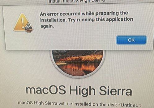
Now there's only one last thing that I can't successfully installed high sierra.
I use the same method as bigsur+oclp and monterey+oclp to install highsierra,is this right?
If I format the hard disk as MacOS extended+guid, this error was reported halfway through the installation
IMG_6235.JPG

If I format the hard disk as APFS, it will install and restart normally, then continue to install and restart again, and then report an error as follow
IMG_6232.JPG

I still don't understand how to install HighSierra10.13.6.
 

Attachments

  • IMG_6235.JPG
    IMG_6235.JPG
    275.5 KB · Views: 54
  • IMG_6232.JPG
    IMG_6232.JPG
    35.7 KB · Views: 72
I used to use Nick's BIOS.
For his week,I used geekbench5.4.4 to test 3 BIOS provided by you, but the two kinds of BIOS of 4170 roms can't pass geekbench's metal test.
The following is the result:
nick's 4150rom: ok, metal-score:17000-18000
WX4150_ GOP: ok, metal-score:21000-22000
WX4170_ GOP: get stuck at 34sec then crash, Tested for 5 times, only passed the test for the first time, metal-score: 27000.
WX4170_ GOP_ ALT_ VRAM: get stuck at 34sec then crash, Test only once.
View attachment 1962321
I don't know why the two kinds of BIOS of 4170 can't pass the test. They both get stuck at Gaussian blur for 34 seconds, and then the black screen crashes
It's also strange and happy that under the same core frequency of 1053mhz and video memory frequency of 1500mhz, the score of BIOS you provide is much higher.
GeekBench Metal scores generally are not reproducible as it doesn't allow for a warmup time of the GPU power management. Pretty useless that way.
You absolutely have to use a different Metal benchmark in order to be able to compare performance.
 
First of all, thank you and @dfranetic for your help about wx4170 vbios.
Now there's only one last thing that I can't successfully installed high sierra.
I use the same method as bigsur+oclp and monterey+oclp to install highsierra,is this right?
If I format the hard disk as MacOS extended+guid, this error was reported halfway through the installation
View attachment 1962417
If I format the hard disk as APFS, it will install and restart normally, then continue to install and restart again, and then report an error as follow
View attachment 1962418
I still don't understand how to install HighSierra10.13.6.
High Sierra is still supported and would not need OCLP to be installed in the first place, only to be used with GPU acceleration.

Try to disable SecureBootModel, but I would avoid installing and booting High Sierra since it overwrites the Big Sur and Monterey preboot partition and you may end up not being able to boot into Big Sur/Monterey, again. This has been described in detail on the first post.

Edit:
My personal recommendation is: Avoid using High Sierra if not absolutely necessary. More pain than gain.
 
Last edited:
Try to disable SecureBootModel, but I would avoid installing and booting High Sierra since it overwrites the Big Sur and Monterey preboot partition and you may and up not being able to boot into Big Sur/Monterey, again. This has been described in detail on the first post.
Thankyou, my English is terrible. I missed the info of the first page and disable securebootmodel. In order to avoid being unable to boot back into Monterey, I'll try to install it again before reinstalling Monterey next time. This thread has really helped me a lot. Thank everyone who helped me.
 
  • Like
Reactions: Ausdauersportler
To add to @Ausdauersportler 's answer: If you have a clip and CH341a programmer, just program the bare (unsoldered) BIOS chip before bringing it to the 'soldering shop'. Also, while they are at it, do ask them to remove those two 0402-sized jumpers connecting the temp. sensor IC to the SMBus - thus you'll avoid address collisions in iMac11,x (and this has no side effect if the card will be used in an iMac12,2).

My card is posted in the post below and I don't have a reference to locate the jumpers you said above. Your images about the jumpers was slightly different from my card. Luckily it does have the RP1 resistor group and maybe all I have to do is soldering in the EEPROM chip.

 
Experimental AMD RX 5500 XT 4GB (Extract from Sonnet eGPU Breakaway Puck)

Tested on Big Sur in a 27-inch iMac 2010

I adapted a MXM-A 2 pipe heatsink (only for tests, you need at least a 3 pipe for this card I guess, the mod is quite complicated). Neither of the two x-bracket formats is suitable due to the components

As predicted by @highvoltage12v here, the card does not deliver a PWM signal,

I assume that the original vbios has GOP because I was able to get the OpenCore bootpicker but without active backlight,

So I did the "hot wire solution" to have a display to test,

I add the boot-args agdpmod=pikera because the screen comes black when loading the OS and graphics drivers,

Additional info :

- No temp reading
- No graphics acceleration on High Sierra, I guess from Catalina (system released with iMac Retina 5K, 27-inch, 2020)
- No external display from miniDisplay port
- Booting on Windows 10 UEFI
- No POST on iMac12,2 (SMBus likely)
- iMac11,3 sleep and wake fully functional

I attach the vBios, maybe the PWM signal can be recovered? Unless it's hardware...

**update**
Score + vBios attached (the first was saved with GPU-z but incomplete)

(Sorry for the translation)
Nice work!

But be warned: You should not be using the card without any X-Bracket at all! The card will bend and the solder balls of the GPU will break sooner or later.
 
Nice work!

But be warned: You should not be using the card without any X-Bracket at all! The card will bend and the solder balls of the GPU will break sooner or later.
I know it's not good, but unfortunately the board doesn't allow to fix an X-Bracket because of the components (whether it's the small or large size)
The card was fixed like this on the heatsink of the Sonnet
I made sure to fix it without forcing it too much, just that it doesn't move
 

Attachments

  • IMG_3341.jpeg
    IMG_3341.jpeg
    636.3 KB · Views: 144
  • Like
Reactions: highvoltage12v
While we are discussing Programmers:
For those of you that use the CH341a BLACK EDITION programmer. You will quickly realize that although your BIOS chip is receiving the correct 3.3V, the DATA lines are running at full 5V! This is not good for the BIOS chips in the long run. You may be able to get away with this for a while, but I can tell you from experience doing thousands of these programming writes, that you will eventually cause the BIOS chip to fail at this voltage.

You can search online for a tutorial on how to bring this back down to 3.3V, but in a nutshell:

ch341a_3.3Vmod.jpeg


You need to lift pin 28 (VCC) off its pad, to disconnect it from the 5V USB feed. Using a 22 gauge thin wire, connect it to the middle pin of the AMS117 Voltage Regulator (V out). Now pin 28 will receive 3.3V. You need to balance this out by connecting pin 9 (V3) to the AMS117 (V in). Pin 9 does NOT need to be lifted off the pad.

Nick.
 
While we are discussing Programmers:
For those of you that use the CH341a BLACK EDITION programmer. You will quickly realize that although your BIOS chip is receiving the correct 3.3V, the DATA lines are running at full 5V! This is not good for the BIOS chips in the long run. You may be able to get away with this for a while, but I can tell you from experience doing thousands of these programming writes, that you will eventually cause the BIOS chip to fail at this voltage.

You can search online for a tutorial on how to bring this back down to 3.3V, but in a nutshell:

View attachment 1963376


You need to lift pin 28 (VCC) off its pad, to disconnect it from the 5V USB feed. Using a 22 gauge thin wire, connect it to the middle pin of the AMS117 Voltage Regulator (V out). Now pin 28 will receive 3.3V. You need to balance this out by connecting pin 9 (V3) to the AMS117 (V in). Pin 9 does NOT need to be lifted off the pad.

Nick.
Another solution:
 
Hello, Everyone

I can’t turn on my iMac (Late 2011, 27-inch, intel i7, Nvidia k3000m) if my BT/Camera cable and LCD cable connect to logic board at the same time, but it will turn on if one of it plug out, naturally if I do that I’ll lose function (Bluetooth or No screen), if I plug both in, and hit the power bottom then the fan will only spin 3 seconds before shut off, then nothing happen, I already change logic board, it’s really frustrating and draining that unable to solve the damn issue

P.S
I did successfully boot into system after remove BT/Camera cable, then connect it afterward, which did bring Bluetooth function, but if I hit shutdown, next time I won’t be able to turn on, same issue happen

Please help
 
Hi guys, I am new to the forum. Many thanks for your great work.
I found a k2100m gpu but I noticed that when I compare it to other k2100m cards, there are two transistors missing.
Do you know why? Will I have an issue flashing the new bios to this card?

Thanx!
 

Attachments

  • 89.jpg
    89.jpg
    199.9 KB · Views: 171
Hi guys, I am new to the forum. Many thanks for your great work.
I found a k2100m gpu but I noticed that when I compare it to other k2100m cards, there are two transistors missing.
Do you know why? Will I have an issue flashing the new bios to this card?

Thanx!
Your card is missing two tantalum (filtering) capacitors. Those are likely required to properly supply power, however the card may work if those lacking capacitors are connected in parallel to the one next to them, but only unreliably and in low power settings. Are there any other (physical) damages visible on the card? You can probably solder those two missing capacitors on the card - they should be the same value and size as the one still holding onto the card.
 
Your card is missing two tantalum (filtering) capacitors. Those are likely required to properly supply power, however the card may work if those lacking capacitors are connected in parallel to the one next to them, but only unreliably and in low power settings. Are there any other (physical) damages visible on the card? You can probably solder those two missing capacitors on the card - they should be the same value and size as the one still holding onto the card.
Thank you so much for your kind and prompt reply. Just to be safe I will not proceed to buy this card. I will try to find one which includes all three tantalum capacitors. Many thanks.

Fyi, I want to install this card to my 2011 21.5" iMac so as I can upgrade it to Big Sur (or even Monterey if OCPL patches the missing nvidia kepler kexts).
 
Register on MacRumors! This sidebar will go away, and you'll see fewer ads.